TUHOMC1006STB Controller
Human Advanced Co., Ltd.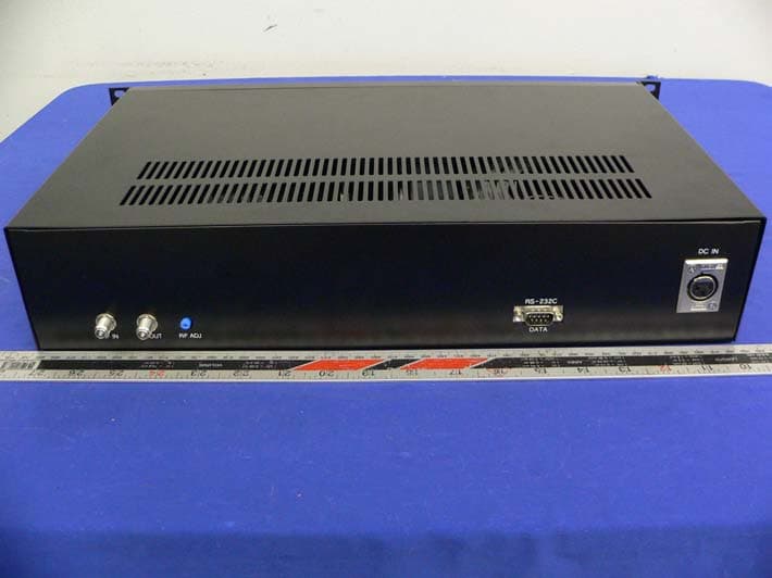
Click to zoom
Application Details
- Equipment Class
- JBP - Part 15 Class B Computing Device Peripheral
- Date of Grant
- Dec 16, 2005
- Application Purpose
- Original Equipment
- Date of Application
- Dec 16, 2005
- Equipment Note
- STB Controller
- Company
- Human Advanced Co., Ltd.
- Country
- South Korea
Documents & Files
Document Text
Text extracted from the exhibit documents filed with the FCC. Open a document above to read the original.
Users Manual
STB Controller OMC 1006 USER MANUAL Rev. 2 3F Poi Bldg., 229-3 Poi-dong, Gangnam-Gu, Seoul, Korea 135-964 Tel: +82-2-575-6213 Fax: +82-2-572-5938 http://www.huad.co.kr Note: The specification and contents in this manual is subject to change. Table of Contents Introduction 1 Overview 뀉뀉뀉뀉뀉뀉뀉뀉뀉뀉 .....1 Function 뀉뀉뀉뀉뀉뀉뀉뀉뀉뀉뀉 1 Product Overview 2 Front View 뀉뀉뀉뀉뀉뀉뀉뀉뀉뀉 ....2 Rear View 뀉뀉뀉뀉뀉뀉뀉뀉뀉뀉 ....3 Operation 4 Initial Screen 뀉뀉뀉뀉 .......... 뀉뀉뀉뀉 ....4 How to set CH for STB Control 뀉뀉뀉뀉뀉 .... ? Force ON 뀉뀉뀉뀉뀉뀉뀉뀉뀉 . 뀉 ....4 Force OFF 뀉뀉뀉 . 뀉뀉뀉뀉뀉 .... 뀉 .....5 Remote Monitoring of the STB 뀉뀉뀉뀉뀉뀉 ..6 Troubleshooting of RS-232C Port 뀉뀉뀉뀉뀉 ....7 Connection Diagram 8 Technical Specification 9 Huad Co., Ltd. USER MANUAL 1 Introduction Overview STB Controller, OMC 1006, is the equipment to receive upstream data from the STB and transmit it to Media Server via its dedicateed frequency. The STB receives downstream data from Media Server and control the STB with this data. STB Controller can control independantly the STB with its own function. Communication method between STB Controller and the STB is Binary FSK. Function 1) RF Modem STB Controller has RF Modem Function to transmit command and control data from the STB to Media Server. 2) Controller STB Controller can control the STB via Key buttons on the front panel. (i.e. Force Tune, Forced Power on/off.) 3) Output Level Adjustment Adjust RF Output Level to maintain stabilized level at the terminal. 4) Remote Monitoring of the STB STB Controller has the built-in protocol to poll the status of the STB at every 500ms. 5) LCD Indicator Indicate the status of data input and operation. 6) Troubleshooting of Serial Port STB Controller has its own protocol to check RS-232C Port Status. 7) RACK Mountable Type Standard 19” Rack mountable. Huad Co., Ltd. USER MANUAL 2 Product Overview Front View ① ② ③④⑤⑥⑦ ⑧ ⑨⑩⑪ POWER SWITCH Power On/Off toggle switch LCD DISPLAY Display input/output data and operation status LED for Tx & Rx LED is blinking when STB Controller transmits and receives data INPUT LED LED indicator for ⑤ ~ ⑦ button on front panel OFF KEY Force TV to power off ON KEY Force TV to Power on CH KEY Set Channel No. ⑧ NUMERIC KEY 0~9 Numeric Button ⑨ ESC KEY To quit input process at each function. ⑩ MODE KEY Set MODE ⑪ ENTER KEY Apply input data for function. Huad Co., Ltd. USER MANUAL 3 Rear View RF INPUT Upstream RF Signal Input RF OUT RF Output Port RF ADJ Adjust RF Output Level RS232C PORT RS232C Communication Port DC POWER IN Cannon Jack for DC 12V/2A Power Input ① ② ③ ④ ⑤ Huad Co., Ltd. USER MANUAL 4 Operation 1) Initial Screen When STB Controller is power on state, you will see the below message. 2) How to set CH for STB Control z Press CH button on front panel, you will see blinking prompts on LCD screen. z Enter a channel number that you want to tune by using numeric button on front panel. Then, press ENTER button. You will see the changed CH number. z LCD Screen returns to the initial screen. 3) Force ON Control the STB to be tuned on with preset CH Number forcibly. z Press ON button on front panel. You will see the channel information that you preset above. CHANNEL SELECT CH : 뀉 뀉 CHANNEL SELECT CH : 0 4 OXFORD MEDIA PPV System POWER ON CH:04 Press Enter key. OXFORD MEDIA PPV System Huad Co., Ltd. USER MANUAL 5 z According to LCD screen instruction, press ENTER to send the data to STB. z The screen will return to the initial screen after finishing data transmission. 4) Force OFF Control the STB to power off TV by force. z Press OFF button on front panel. You will see the below message. z According to the instruction displayed, press ENTER key on front panel. z The screen will return to the initial screen after finishing data transmission. POWER ON CH:04 Sendingᆞᆞᆞ OXFORD MEDIA PPV System POWER OFF Sendingᆞᆞᆞ OXFORD MEDIA PPV System POWER OFF Press Enter key. Huad Co., Ltd. USER MANUAL 6 5) Troubleshooting of RS-232C Port OMC1006 has its own protocol to check RS-232C port status. Therefore, the user needs to check the communication status of serial port via this protocol. Please contact Technical Engineer of Oxford Media Corp. to obtain the protocol. 6) Additional Message on LCD Once OMC1006 receives the data from RCU, OMC1006 displays “remocon data” message on LCD screen. If OMC 1006 receives the protocol of Serial Query, then OMC1006 displays the status of RS-232C Port Status. Huad Co., Ltd. USER MANUAL 7 Connection Diagram Media Server L H Diplexer RS-232 Cross Connection RF Cable Network Huad Co., Ltd. USER MANUAL 8 Technical Specification Control Part MCU Atmega128(Atmel) Clock 16 MHz RAM 4 Bytes ROM 128 Kbytes RF Specification RF Modem Section Symbol Rate: 9600 bps 9600 bps TX Data Modulation Method Binary FSK TX Center Frequency 108.00 MHz TX Frequency Deviation +/- 50 KHz TX RF Output Level 45dBmV Nominal TX RF output Control Range -20dB TX Return loss 16 dB RF Modem Section Symbol Rate 9600 bps RX Demodulation Method Binary FSK RX Center Frequency 10.7 MHz RX Signal Frequency Deviation +/- 50 kHz RX Return Loss 16 dB RX Input Level -18dBmV min to +38dBmV Max RF Port Impedance 75 Ohms both connectors Environmental Specification Input Voltage +12VDC/2A External Power Adapter - Input Voltage : 115VAC+/- 10%, 60Hz - Output Voltage : +12VDC/2A Operating Temperature Range 0 to +50 degrees C Huad Co., Ltd. USER MANUAL 9 Operating Humidity Range 20 to 95% (non-condensing) Physical Specification Dimensions (W x H x D) 484 x 88 x 290 (mm) (2RU high) Weight 5.0 kg Connectors RS-232 : 1 each, 9 pin Sub-Miniature type 뀉 ” male RF Output : F type RF receptacle RF Input : F type RF receptacle DC Power Input : Cannon(Male) FCC Warning FCC15.19 This device is verified to comply with part 15 of the FCC Rules for use with cable television service. FCC 15.105 Note: This equipment has been tested and found to comply with the limits for a Class B digital device, pursuant to part 15 of the FCC Rules. These limits are designed to provi…
Text truncated - open the document above for the full version.
Block Diagram
Huad Co., Ltd. Product Information 3F, Poi Bldg, 229-3, Poi-dong, Gangnam-gu, Seoul, South Korea 135-964 Tel: +82-2-575-6213 Fax: +82-2-572-5938 z STBC Block Diagram RS-232C INTERFACE MICOM MEMORY KEY INPUT LCD DISPLAY FSK MODULATOR FSK DEMOD BPF BPF BPF BPF H L ATT ATT RF OUT TEST OUTPUT AMP MOD 1 MOD 4 MOD 2 MOD 3 TTL(TX) TTL(RX)
External Photos
Human Advanced Co., Ltd FCC ID: TUHOMC1006 Report # R0511162(OMC1006)Exhibits FCC Class B ID Test Report EXHIBIT C - EUT PHOTOGRAPHS Chassis – Front View Chassis – Rear View
ID Label/Location Info
EXHIBIT A - FCC ID LABEL INFORMATION Proposed FCC ID Label Specifications: Text is white in color and is left justified. Labels are printed in indelible ink on permanent adhesive backing or silk-screened and shall be affixed at a conspicuous location on the EUT. Proposed Label Location on EUT Chassis Bottom View /Proposed FCC Label Location For products ship to Canada, please add the following to the product: "This Class B digital apparatus complies with Canadian ICES-003" FCC ID : TUHOMC1006 This device complies with Part 15 of the FCC Rules. Operation is subject to the following two conditions: (1) this device may not cause harmful interference, and (2) this device must accept any interference received, including interference that ma y cause undesired operation.
Internal Photos
Human Advanced Co., Ltd FCC ID: TUHOMC1006 Report # R0511162(OMC1006)Exhibits FCC Class B ID Test Report EUT – Chassis off View EUT – Component View (1)_ Human Advanced Co., Ltd FCC ID: TUHOMC1006 Report # R0511162(OMC1006)Exhibits FCC Class B ID Test Report EUT – Solder View (1)_ EUT – Component View (2)_ Human Advanced Co., Ltd FCC ID: TUHOMC1006 Report # R0511162(OMC1006)Exhibits FCC Class B ID Test Report EUT – Solder View (2)_ Power Supply View
Test Report
Note: The test report is specially limited to the use of the above client company and this particular sample only. It may not be duplicated without prior written consent of Bay Area Compliance Laboratory Corporation. This report must not be used by the client to claim product certification, approval, or endorsement by NVLAP, NIST or any agency of the U.S. Government. FCC PART 15 CLASS B EMI MEASUREMENT AND TEST REPORT For Human Advanced Co., Ltd 3Fl., Poi Bldg., #229-3, Poi-Dong, Kangnam-Gu, Seoul, Korea 135-964 FCC ID: TUHOMC1006 This Report Concerns: Original Report Equipment Type: STB controller Test Engineer: Oscar Au Report Number: R0511162 Report Date: 2005-12-6 Reviewed By: Snell Leong Prepared By: Bay Area Compliance Laboratory Corporation 230 Commercial Street Sunnyvale, CA 94085 Tel: (408) 732-9162 Fax: (408) 732-9164 Human Advanced Co., Ltd FCC ID: TUHOMC1006 Report # R0511162(OMC1006)Rpt FCC Class B ID Test Report Page 2 of 15 TABLE OF CONTENTS GENERAL INFORMATION.......................................................................................................................................3 PRODUCT DESCRIPTION FOR EQUIPMENT UNDER TEST (EUT) ....................................................................................3 OBJECTIVE...................................................................................................................................................................3 RELATED SUBMITTAL(S)/GRANT(S).............................................................................................................................3 TEST METHODOLOGY..................................................................................................................................................3 TEST FACILITY.............................................................................................................................................................3 SYSTEM TEST CONFIGURATION ..........................................................................................................................5 JUSTIFICATION.............................................................................................................................................................5 EUT EXERCISE SOFTWARE..........................................................................................................................................5 SPECIAL ACCESSORIES.................................................................................................................................................5 SCHEMATICS / BLOCK DIAGRAM.................................................................................................................................5 EQUIPMENT MODIFICATIONS.......................................................................................................................................5 LOCAL SUPPORT EQUIPMENT LIST AND DETAILS........................................................................................................5 INTERFACE PORTS AND CABLING.................................................................................................................................6 CONFIGURATION OF TEST SYSTEM..............................................................................................................................7 TEST SETUP BLOCK DIAGRAM.....................................................................................................................................7 SUMMARY OF TEST REPORT.................................................................................................................................8 §15.107 - CONDUCTED EMISSIONS ........................................................................................................................9 MEASUREMENT UNCERTAINTY....................................................................................................................................9 EUT SETUP..................................................................................................................................................................9 RECEIVER SETUP..........................................................................................................................................................9 TEST EQUIPMENT LIST AND DETAILS...........................................................................................................................9 TEST PROCEDURE........................................................................................................................................................9 TEST RESULTS SUMMARY..........................................................................................................................................10 CONDUCTED EMISSIONS TEST DATA.........................................................................................................................10 PLOTS OF CONDUCTED EMISSION..............................................................................................................................10 §15.109 - RADIATED EMISSIONS...........................................................................................................................13 MEASUREMENT UNCERTAINTY..................................................................................................................................13 EUT SETUP................................................................................................................................................................13 RECEIVER SETUP........................................................................................................................................................13 TEST EQUIPMENT LIST AND DETAILS.........................................................................................................................14 TEST PROCEDURE..................................................................…
Text truncated - open the document above for the full version.
Test Setup Photos
Human Advanced Co., Ltd FCC ID: TUHOMC1006 Report # R0511162(OMC1006)Exhibits FCC Class B ID Test Report EXHIBIT B - TEST SETUP PHOTOGRAPHS Conducted Emission AC Line Human Advanced Co., Ltd FCC ID: TUHOMC1006 Report # R0511162(OMC1006)Exhibits FCC Class B ID Test Report Radiated Emission
Contact Information
Applicant
Sung Wi Hong(Executive Team Manager)
Test Firm
Bay Area Compliance LaboratoryJohn Chan
Technical Specifications
| # | Rule Parts | Frequency Range | Power Output |
|---|---|---|---|
| 1 | 15B | - | - |
Other Applications from Human Advanced Co., Ltd.
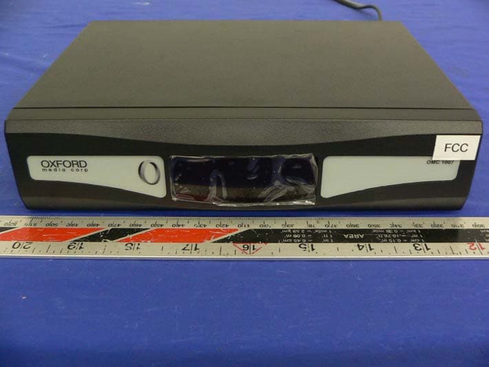
TUHOMC1007
Dec 16, 2005RF STB
Equipment Class
HID - Part 15 TV Interface Device