TUHOMC1007RF STB
Human Advanced Co., Ltd.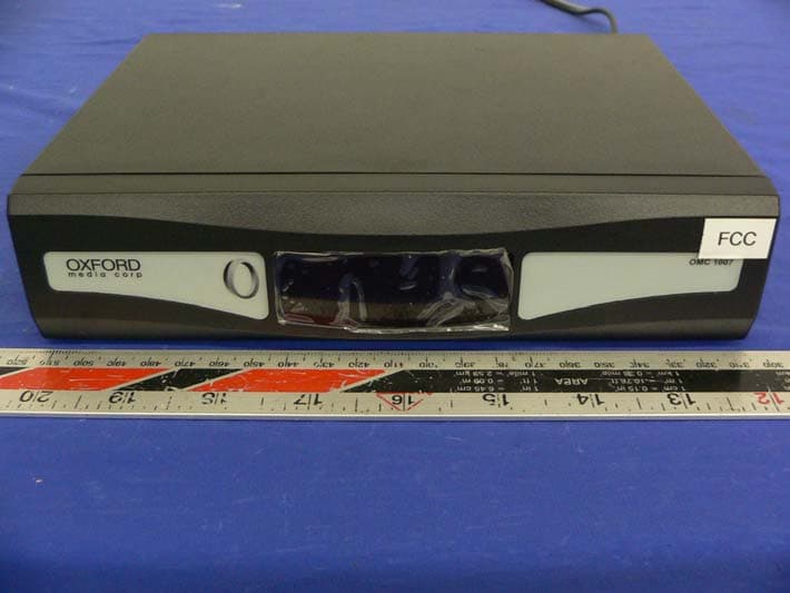
Click to zoom
Application Details
- Equipment Class
- HID - Part 15 TV Interface Device
- Date of Grant
- Dec 16, 2005
- Application Purpose
- Original Equipment
- Date of Application
- Dec 16, 2005
- Equipment Note
- RF STB
- Frequency Range
- 61.25000000 - 71.75000000
- Company
- Human Advanced Co., Ltd.
- Country
- South Korea
Documents & Files
Document Text
Text extracted from the exhibit documents filed with the FCC. Open a document above to read the original.
Users Manual
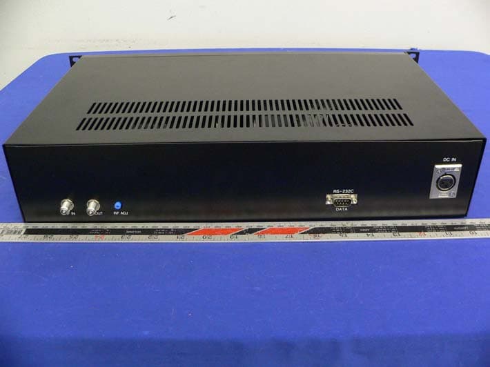
1 RF Set-Top-Box OMC1007 USER MANUAL Rev. 1 3F Poi Bldg., 229-3 Poi-dong, Gangnam-Gu, Seoul, Korea 135-964 Tel: +82-2-575-6213 Fax: +82-2-572-5938 http://www.huad.co.kr Note: The specification and contents in this manual is subject to change. 2 IMPORTANT SAFETY INSTRUCTIONS: Important safety instructions shall be provided with each apparatus. This information shall be given in a separate booklet or sheet, or be located before any operating instructions in an instruction for installation for use and supplied with the country where the apparatus is intended to be used. The important safety instructions shall be entitled 밒 mportant Safety Instructions ? The following safety instructions shall be included where applicable, and, when used, shall be verbatim as follows. Additional safety information may be included by adding statements after the end of the following safety instruction list. At the manufacturer 밒 option, a picture or drawing that illustrates the intent of a specific safety instruction may be placed immediately adjacent to that safety instruction: 1) Read these instructions. 2) Keep these instructions. 3) Heed all warnings. 4) Follow all instructions. 5) Do not use this apparatus near water. 6) Clean only with a damp cloth. 7) Do not block any of the ventilation openings. Install in accordance with the manufacturer 밒 instruction. 8) Do not install near any heat sources such as radiators, heat registers, stoves, or other apparatus (including amplifiers) that produce heat. 9) Do not defeat the safety purpose of the polarized or grounding type plug. A polarized plug has two blades with one wider than the other. A grounding type plug has two blades and a third prong is provided for your safety. When the provided plug does not fit into your outlet, consult an electrician for replacement of the obsolete outlet. 10) Protect the power cord form being walked on or pinched particularly at plugs, convenience receptacles, and the point where they exit from the apparatus. 11) Only use the attachments/ accessories specified by the manufacturer. 12) Use only with a cart, stand, tripod, bracket, or table specified by the manufacturer, or sold with the apparatus. When a cart is used, use caution when moving the cart/apparatus combination to avoid injury from tip-over. 3 13) Unplug this apparatus during lightning storms or when unused for long periods of time. 14) Refer all servicing to qualified service personnel. Servicing is required when the apparatus has been damaged in any way, such as power supply cord or plug is damaged, liquid has been spilled or objects have fallen into the apparatus, the apparatus has been exposed to rain or moisture, does not operate normally, or has been dropped. 15) "WARNING – To Reduce The Risk Of Fire Or Electric Shock, Do Not Expose This Product To Rain Or Moisture." Shocking Hazard Marking and Associated Graphical Symbols or Equivalent. Explanation of Safety Related Symbols or Equivalent words. 4 Remark: The product label is attached on the bottom. 5 Table of Contents Remote Control Unit 1 Product Overview 2 Front View 밒밒밒밒밒밒밒밒밒밒 ....2 Rear View 밒밒밒밒밒밒밒밒밒밒 ....3 STB Installation 4 Connecting to TV & Cable Network 밒밒밒밒밒 .4 Getting Started 5 Power On/Off 밒밒밒밒밒밒밒밒 . 밒 .....5 Force Tune 밒밒밒밒밒밒밒밒 .... 밒 .....5 Surf Free-to-Guest Channel 밒밒밒밒밒 . 밒 ....5 PPV/VOD Service Use 밒밒밒밒밒밒 . 밒 .....5 Previous Viewing VOD Content 밒밒밒밒 .... 밒 ...8 Technical Specification 9 6 Remote Control Unit (RCU, C500R) MENU Key to access VOD Channel LAST Key to return to VOD Channel or previous Channel Arrow & OK key to move VOD Contents and select Movie Fast Forward, Play/Pause and Rewind Function for VOD Contents 7 Product Overview Front View COMPANY LOGO LED SCREEN Display the channel information set by RCU MODEL NUMBER 8 Rear View ① AC RECEPTACLE FOR TV 2 blade polarized AC receptacle for TV POWER CORD 110-120 VAC 60Hz power source REMOTE IR PORT Screw to fix the cover to the body RF OUT For connecting to TV TV OUTPUT CHANNEL SWITCH Switch Channel 3 or 4. RF IN For connecting to RF cable coming from Headend System. 9 STB Installation Connecting to TV & Cable Network [1] Connect RF cable to Antenna IN port on rear panel of TV. [2] Connect AC power cable from TV to AC receptacle on the STB. [3] Connect RF source cable to RF IN at back panel of the STB [4] Connect AC power cord of STB to Power soruce. Antenna IN AC PWR RF IN [1] [2] [3] [4] TO CABLE NETOWRK 10 Getting Started POWER ON/OFF The STB is always standby mode with impressed power when it is not used. z Press Power button on RCU to have the STB power on/off state. FORCE TUNE Once the STB has power on, the STB is set to channel 3 or 4. The channel 3 or 4 can be changed by switch at rear panel. SURF FREE-TO-GUEST CHANNEL z Press channel up and down key to surf Free-to-Guest Channel. PPV/VOD SERVICE USE PPV/VOD Ordering sequence is as follows.; 11 z When the TV set is turned on, TV is tuned to CH3 or CH4 of Barker Channel as shown below. z Select highlighted item and press UP/DOWN/LEFT/RIGHT keys on RCU to move the category and select the movie. Menu contents will be shown on screen. From menu lists you can select movie that you want to order for view. z Press OK key on RCU to select a movie title. 12 z Press OK key on RCU to go to next steps after selecting a movie title. Then, you will see Payment Method Screen to make payment. z Press OK key on RCU after you select your preferrable payment method. The selected Payment Method will be highlighted. z If you select Credit Card to pay this movie, enter your Credit Card No. by using numeric keys on RCU. z Now, you can enjoy the movie that you purchased. PREVIOUS VIEWING VOD CONTENTS z Press LAST key on RCU to view Previous Viewing VOD content. 13 Technical Specification Control Part MCU MX10FBPD (Micronics) Clock Speed 11.0592 MHz ROM 64 Kbytes RAM 256 Bytes RF Specification Video/Audio Frequency Range 54 to 450 MHz Channels TV 2 – 61 (CATV ? - YY ? Vide…
Text truncated - open the document above for the full version.
Block Diagram
STB BLOCK DIAGRAM VIDEO DESCRAMBLER 3IN1 TUNER SWITCH AMP AUDIO IN VIDEO DRIVER VIDEO IN 6DB AMP VIDEO OUT IN1 IN2 OUT AUDIO OUT INPUT OUTPUT TRANS NL POWER CIRCUIT COMMUNICATION MODEM RESET : CPU CONTROL LINE: ANALOG SIG. LINE NL RELAY IN / OUT TO CPU UART UART DC+33VDC+12V DC +5V OUTPUT 13.2VAC CT 0.8A FUSE 250V/0.5A T AC PLUG 120V/ 60HZ INPUT AC120V /60HZ : LIVE AC OUTLET 120V/60HZ400W MAX
External Photos
Human Advanced Co., Ltd FCC ID: TUHOMC1007 Report # R0511162(OMC1007)Exhibits FCC Class B ID Test Report EXHIBIT C - EUT PHOTOGRAPHS Chassis – Front View Chassis – Rear View
ID Label/Location Info
EXHIBIT A - FCC ID LABEL INFORMATION Proposed FCC ID Label Specifications: Text is white in color and is left justified. Labels are printed in indelible ink on permanent adhesive backing or silk-screened and shall be affixed at a conspicuous location on the EUT. Proposed Label Location on EUT Chassis Bottom View /Proposed FCC Label Location For products ship to Canada, please add the following to the product: "This Class B digital apparatus complies with Canadian ICES-003" FCC ID: TUHOMC1007 This device complies with Part 15 of the FCC Rules. Operation is subject to the following two conditions: (1) this device may not cause harmful interference, and (2) this device must accept any interference received, including interference that ma y cause undesired operation.
Internal Photos
Human Advanced Co., Ltd FCC ID: TUHOMC1007 Report # R0511162(OMC1007)Exhibits FCC Class B ID Test Report EUT – Chassis off View EUT – Component View Human Advanced Co., Ltd FCC ID: TUHOMC1007 Report # R0511162(OMC1007)Exhibits FCC Class B ID Test Report EUT – Solder View
Test Report
Note: The test report is specially limited to the use of the above client company and this particular sample only. It may not be duplicated without prior written consent of Bay Area Compliance Laboratory Corporation. This report must not be used by the client to claim product certification, approval, or endorsement by NVLAP, NIST or any agency of the U.S. Government. FCC PART 15 CLASS B EMI MEASUREMENT AND TEST REPORT For Human Advanced Co., Ltd 3Fl., Poi Bldg., #229-3, Poi-Dong, Kangnam-Gu,Seoul, Korea 135-964 FCC ID: TUHOMC1007 This Report Concerns: Original Report Equipment Type: RF STB Test Engineer: Oscar Au Report Number: R0511162 Report Date: 2005-12-6 Reviewed By: Snell Leong Prepared By: Bay Area Compliance Laboratory Corporation 230 Commercial Street Sunnyvale, CA 94085 Tel: (408) 732-9162 Fax: (408) 732-9164 Human Advanced Co., Ltd FCC ID: TUHOMC1007 Report # R0511162(OMC1007)Rpt FCC Class B ID Test Report Page 2 of 28 TABLE OF CONTENTS GENERAL INFORMATION.......................................................................................................................................4 PRODUCT DESCRIPTION FOR EQUIPMENT UNDER TEST (EUT) ....................................................................................4 OBJECTIVE...................................................................................................................................................................4 RELATED SUBMITTAL(S)/GRANT(S).............................................................................................................................4 TEST METHODOLOGY..................................................................................................................................................4 TEST FACILITY.............................................................................................................................................................4 SYSTEM TEST CONFIGURATION ..........................................................................................................................6 JUSTIFICATION.............................................................................................................................................................6 EUT EXERCISE SOFTWARE..........................................................................................................................................6 SPECIAL ACCESSORIES.................................................................................................................................................6 SCHEMATICS / BLOCK DIAGRAM.................................................................................................................................6 EQUIPMENT MODIFICATIONS.......................................................................................................................................6 LOCAL SUPPORT EQUIPMENT LIST AND DETAILS........................................................................................................6 INTERFACE PORTS AND CABLING.................................................................................................................................7 CONFIGURATION OF TEST SYSTEM..............................................................................................................................8 TEST SETUP BLOCK DIAGRAM.....................................................................................................................................8 SUMMARY OF TEST REPORT.................................................................................................................................9 §15.107 - CONDUCTED EMISSIONS ......................................................................................................................10 MEASUREMENT UNCERTAINTY..................................................................................................................................10 EUT SETUP................................................................................................................................................................10 RECEIVER SETUP........................................................................................................................................................10 TEST EQUIPMENT LIST AND DETAILS.........................................................................................................................10 TEST PROCEDURE......................................................................................................................................................10 TEST RESULTS SUMMARY..........................................................................................................................................11 CONDUCTED EMISSIONS TEST DATA.........................................................................................................................11 PLOTS OF CONDUCTED EMISSION..............................................................................................................................11 §15.109 - RADIATED EMISSIONS...........................................................................................................................14 MEASUREMENT UNCERTAINTY..................................................................................................................................14 EUT SETUP................................................................................................................................................................14 RECEIVER SETUP........................................................................................................................................................14 TEST EQUIPMENT LIST AND DETAILS.........................................................................................................................15 TEST PROCEDURE.................................................................................…
Text truncated - open the document above for the full version.
Test Setup Photos
Human Advanced Co., Ltd FCC ID: TUHOMC1007 Report # R0511162(OMC1007)Exhibits FCC Class B ID Test Report EXHIBIT B - TEST SETUP PHOTOGRAPHS Conducted Emission AC Line Human Advanced Co., Ltd FCC ID: TUHOMC1007 Report # R0511162(OMC1007)Exhibits FCC Class B ID Test Report Radiated Emission Human Advanced Co., Ltd FCC ID: TUHOMC1007 Report # R0511162(OMC1007)Exhibits FCC Class B ID Test Report Antenna Power Conduction Measurement Ouput Signal Level Measurement Human Advanced Co., Ltd FCC ID: TUHOMC1007 Report # R0511162(OMC1007)Exhibits FCC Class B ID Test Report Output Terminal Conducted Spurious Emission Measurement Transfer Switch Measurement
Contact Information
Applicant
Sung Wi Hong(Executive Team Manager)
Test Firm
Bay Area Compliance LaboratoryJohn Chan
Technical Specifications
| # | Rule Parts | Frequency Range | Power Output |
|---|---|---|---|
| 1 | 15B | 61.25 MHz - 71.75 MHz | - |
Other Applications from Human Advanced Co., Ltd.
TUHOMC1006
Dec 16, 2005STB Controller
Equipment Class
JBP - Part 15 Class B Computing Device Peripheral