Text extracted from the exhibit documents filed with the FCC. Open a document above to read the original.
Class A Digital Device This equipment has been tested and found to comply with the limits for a Class A digital device, pursuant to part 15 of the FCC Rules. These limits are designed to provide reasonable protection against harmful interference when the equipment is operated in a commercial environment. This equipment generates, uses, and can radiate radio frequency energy and, if not installed and used in accordance with the instruction manual, may cause harmful interference to radio communications. Operation of this equipment in a residential area is likely to cause harmful interference in which case the user will be required to correct the interference at his own expense. Do Not Change of Modify Any Components Any changes or modifications, especially to the wireless components, not expressly approved by BTE Technologies, Inc. could void the user’s authority to operate the equipment. Acceptable Antenna(s) This device has been designed to operate with the antenna(s) listed below and having a maximum gain of 2.7 dBi. Antennas not included in this list or having a gain greater than 2.7 dBi are strictly prohibited for use with this device. The required antenna im- pedance is 50 ohms. Acceptable antenna(s) include: 1. Linx Technologies 916MHz 1/4 Wave Whip Antenna (ANT-916-CW-QW) To reduce potential radio interference to other users, the antenna type and its gain should be so chosen that the equivalent isotropically radiated power (e.i.r.p.) is not more than that permitted for successful communication. Preventing interference between the wireless components Interference, which can result in an inability to acquire accurate data, may occur in the following scenarios: a. The antennas of any wireless components are within 3 feet of each other (e.g. the antenna on the new DAQ Box is within 3 feet of the antenna on the Heart Rate Transmitter). b. There is not a direct line of sight between the antennas of the wireless compo- nents. In addition, any metal that is between the antennas will cause interference. You may prevent interference by maintaining your system in the following manner: a. Do not allow the Heart Rate Transmitter to fall on the floor. b. Regularly check the USB cable and power cable that are attached to the new DAQ Box. c. Verify the antennas are in good working order and properly secured. You may also prevent interference by using the following guidelines: a. Place the new DAQ Box in a location that ensures the antenna of the new DAQ Box will always be at least 3 feet from the antenna on the Heart Rate Transmitter. b. Verify there is a direct line of sight between the DAQ Box antenna and the Heart Rate Transmitter antenna. 4
BTE Technologies Evaluation and Rehabilitation System Manual 2 3 Customer Service BTE strives to provide exceptional customer service. To access a Customer Service Representative: Phone 800.461.6888 (9am-6pm EST Monday thru Friday) Cell 416.717.5789 (After-hours service) Fax 416.398.9108 Email [email protected] Class A Digital Device This equipment has been tested and found to comply with the limits for a Class A digital device, pursuant to part 15 of the FCC Rules. These limits are designed to provide reasonable protection against harmful interference when the equipment is operated in a commercial environment. This equipment generates, uses, and can radiate radio frequency energy and, if not installed and used in accordance with the instruction manual, may cause harmful interference to radio communications. Operation of this equipment in a residential area is likely to cause harmful interference in which case the user will be required to correct the interference at his own expense. Do Not Change of Modify Any Components Any changes or modifications, especially to the wireless components, not expressly approved by BTE Technologies, Inc. could void the user’s authority to operate the equipment. Acceptable Antenna(s) This device has been designed to operate with the antenna(s) listed below and having a maximum gain of 2.7 dBi. Antennas not included in this list or having a gain greater than 2.7 dBi are strictly prohibited for use with this device. The required antenna im- pedance is 50 ohms. Acceptable antenna(s) include: 1. Linx Technologies 916MHz 1/4 Wave Whip Antenna (ANT-916-CW-QW) To reduce potential radio interference to other users, the antenna type and its gain should be so chosen that the equivalent isotropically radiated power (e.i.r.p.) is not more than that permitted for successful communication. Preventing interference between the wireless components Interference, which can result in an inability to acquire accurate data, may occur in the following scenarios: a. The antennas of any wireless components are within 3 feet of each other (e.g. the antenna on the new DAQ Box is within 3 feet of the antenna on the Heart Rate Transmitter). b. There is not a direct line of sight between the antennas of the wireless compo- nents. In addition, any metal that is between the antenna s will cause interference. You may prevent interference by maintaining your system in the following manner: a. Do not allow the Heart Rate Transmitter to fall on the floor. b. Regularly check the USB cable and power cable that are attached to the new DAQ Box. c. Verify the antennas are in good working order and properly secured. You may also prevent interference by using the following guidelines: a. Place the new DAQ Box in a location that ensures the antenna of the new DAQ Box will alw ays be at least 3 feet from the antenna on the Heart Rate Transmitter. b. Verify there is a direct line of sight between the DAQ Box antenna and the Heart Rate Transmitter antenna. 4 TABLE OF CONTENTS 5 Important Information ..................................................................................... 9 Conventions and Symbols Used.................................................................... 12 Assembling the Equipment Upon Arrival ...................................................... 13 Functional Range of Motion (FROM) Pegboard Assembly .......................... 26 The Basics in Using the ER System .............................................................. 31 Installing the Software .................................................................................... 32 Administration Menu....................................................................................... 40 Clinic Information ............................................................................. 40 Practitioner Information ................................................................... 41 Environmental Settings.................................................................... 42 User Manager.................................................................................... 44 Import and Exporting in ODES ........................................................ 45 Heart Rate Comments...................................................................... 48 Job Demand Templates.................................................................... 48 Protocol Hibernation........................................................................ 49 Remove Current Case ...................................................................... 50 Calibrating the Equipment .............................................................................. 51 Calibration of the Hand Grip ............................................................ 52 Pinch Grip Calibration ...................................................................... 54 Algometer Calibration ...................................................................... 55 FOCUS Calibration ........................................................................... 59 Universal Task Master Calibration .................................................. 60 Weight Verification ........................................................................... 64 Auto Calibration................................................................................ 66 Calibration Reports .......................................................................... 67 Adding a Client ................................................................................................ 67 Adding a Client Case ...................................................................................... 69 Finding a Client/Case ...................................................................................... 77 Adding a Test to a Client ................................................................................ 78 Removing a Test from a Client ...............................................................…
Text truncated - open the document above for the full version.
151 These are only guidelines and in most cases these landmarks will work without any problems. However, there are clients who do have anomalies from birth or from injury that may make landmarking in this way difficult. In these cases, document any known anomaly discovered in the process of landmarking so that it may be duplicated for accurate comparison. Cervical Range of Motion Flexion With the client in a seated position, manually landmark the T1 spinous process using a washable marker. Align the sensors in the sagittal plane and place one of the Inclinometers on the T1 spinous process. Place the other over the calvarium. Take the initial reading. Have the client maximally flex the head. Take the final reading.Return the client to a neutral position and repeat these steps two more times. Alternatively, the evaluator may place the Inclinometer on top of the head. 152 Extension With the client in a seated position, manually landmark the T1 spinous process using a washable marker. Align the sensors in the sagittal plane and place one of the Inclinometers laterally on the T1 spinous process. Place the other over the calvarium. Take the initial reading. Have the client maximally extend the head. Take the final reading. Return the client to a neutral position and repeat these steps two more times. Lateral Flexion With the client in a seated position, manually landmark the T1 spinous process using a washable marker. Align the sensors in the coronal plane and place one of the Inclinometers laterally on the T1 spinous process. Place the other over the calvarium. Take the initial reading. Have the client maximally laterally flex the head to one side. Take the final reading. Return the client to a neutral position. Repeat these steps two more times to the same side and then repeat 3 times to the opposite side. Alternatively the superior, or upper-most Inclinometer may be placed on the top of the head. 153 Rotation Only with cervical rotation do you use a single Inclinometer. Have the client lie in a supine position (this will stabilize the client's shoulders). The shoulders should be exposed, to allow the evaluator to note excessive shoulder rotation. Align the sensor in the transverse plane and place the Inclinometer at the superior portion of the head. Take the initial reading. Have the client maximally rotate their head to one side. Take the final reading. Return the client to a neutral position. Repeat these steps two more times to the same side and then repeat 3 times to the opposite side. Thoracic Range of Motion Since thoracic is quite dependent on the individual's posture, it is best to have the client use a military type stance. This will minimize the client's kyphosis. 154 Flexion With the client in a seated or standing position, manually landmark the T1 and T12 spinous processes using a washable marker. Align the sensors in the sagittal plane and place one of the Inclinometers on the T1 spinous process. Place the other at the T12 Spinous Process. Take the initial reading. Have the client maximally flex the thoracic spine. Take the final reading. Return the client to a neutral position and repeat these steps two more times. Minimal Kyphosis With the client in a seated or standing position, manually landmark the T1 and T12 spinous processes using a washable marker. Align the sensors in the sagittal plane. Take the initial reading by zeroing the Inclinometers against a true vertical surface such as a wall, then place one of the Inclinometers on the T1 spinous process. Place the other on the T12 Spinous Process. Take the final reading. Return the client to a neutral position and repeat these steps two more times. Rotation With the client in a standing position, instruct them to forward flex until the thoracic spine is in as horizontal a position as possible. Manually landmark the T1 and T12 spinous processes using a washable marker. Aligning the sensors in the axial and vertical planes, place one of the Inclinometers on the T1 spinous process and place the other at the T12 Spinous Process. Take the initial reading. Have the client maximally rotate the thoracic spine to one side. Take the final reading. Return the client to a neutral position. Repeat these steps two more times to the same side and then repeat 3 times to the opposite side. 155 Lumbosacral Range of Motion Flexion With the client in a standing position, manually landmark the T12 spinous process using a washable marker. Align the sensors in the sagittal plane and place one of the Inclinometers on the T12 spinous process. Place the other at S1 spinous process. Take the initial reading. Have the client maximally flex the lumbar spine. Take the final reading. Return the client to a neutral position and repeat these steps two more times. Extension With the client in a standing position, manually landmark the T12 spinous process using a washable marker. Align the sensors in the sagittal plane and place one of the Inclinometers on the T12 spinous process. Place the other at S1 spinous process. Take the initial reading. Have the client maximally 156 extend the lumbar spine. Take the final reading. Return the client to a neutral position and repeat these steps two more times. Lateral Flexion With the client in a standing position, manually landmark the T12 spinous process using a washable marker. Aligning the sensors in the coronal plane, place one of the Inclinometers on the T12 spinous process and place the other at the sacral midpoint. Take the initial reading. Have the client maximally laterally flex the lumbar spine to one side. Take the final reading. Return the client to a neutral position. Repeat these steps two more times to the same side and then repeat 3 times to the opposite side. Straight Leg Raise Have the client lie in a supine position. Aligning the Master sensor in the sagittal plane, place it along the anterior lower third of the tibia. Take the initial reading. Perform a straight leg raise. Take the final reading at…
Text truncated - open the document above for the full version.
11 22 33 44 A A B B SIZE DWG NO REV SCALE SHEET OF TITLE DRAFTER CHECKED TOLERANCES UNLESS SPECIFIED FRACTION OR .X ` 1/32 .XX ` .01 .XXX ` .005 ANGULAR ` 1 ~ DIMENSIONS IN [ ] ARE METRIC SPECIFICATIONS NOTED NTS 40050099 DAQ RETROFIT,ASSY 11 7455-L NEW RIDGE ROADHANOVER, MD 21076 NOTES:A) APPLY LOCTITE ONLY WHERE NOTED B) REFER TO WORK INSTRUCTION 751W3026 FOR SPECIAL ASSEMBL Y INSTRUCTIONS A. NICOLAISEN 02/07/06 XXXXXX XXXXX 000 B REVISION HISTORY REV DESCRIPTION DATE APPROVED ECO 000 NEW DRAWING 02/07/06 ATN - - - - ITEMS NOT SHOWN : I/N 7 - ANTENNAI/N 8 - POWER CORDI/N 10 - POWER SUPPLY 4 2 1 9 3 6 5 8X 2X SEE NOTE B SEE NOTE B APPLY BLUE 242LOCTITE SEE NOTE B 11
11 22 33 44 A A B B SIZE DWG NO REV SCALE SHEET OF TITLE DRAFTER CHECKED TOLERANCES UNLESS SPECIFIED FRACTION OR .X ` 1/32 .XX ` .01 .XXX ` .005 ANGULAR ` 1 ~ DIMENSIONS IN [ ] ARE METRIC SPECIFICATIONS NOTED NTS 40050100 TRANSMITTER, HR,ASSY, DAQ RETROFIT 11 7455-L NEW RIDGE ROADHANOVER, MD 21076 NOTES:A) NO LOCTITE IS REQUIRED FOR THIS ASSEMBLYB) REFER TO WORK INSTRUCTION 751W3026 FOR SPECIAL ASSEMBL Y INSTRUCTIONS A. NICOLAISEN 02/07/06 XXXXXX XXXXX 000 B REVISION HISTORY REV DESCRIPTION DATE APPROVED ECO 000 NEW DRAWING 02/07/06 ATN - - - - ITEMS NOT SHOWN : I/N 6 - ANTENNAI/N 8 - AA BATTERY CHARGERI/N 9 - AA BATTERYI/N 14 - POS BATTERY LEADI/N 15 - NEG BATTERY LEAD 5 1 4 7 13 3 11 12 10 1 2 3X 2X SEE NOTE B SEE NOTE B 16
BTE Technologies, Inc. – Products Group BTE Technologies, Inc. – Employer/Payer Services 7455-L New Ridge Road – Hanover, MD 21075 8390 E. Crescent Parkway, Suite 120 – Greenwood Village, CO 800-331-8445 410-850-0333 800-206-2972 720-266-0120 February 13, 2006 Confidentiality is not requested for the DAQ retrofit modular product approval. Joseph Perret VP Engineering
BTE Technologies, Inc. – Products Group BTE Technologies, Inc. – Employer/Payer Services 7455-L New Ridge Road – Hanover, MD 21075 8390 E. Crescent Parkway, Suite 120 – Greenwood Village, CO 800-331-8445 410-850-0333 800-206-2972 720-266-0120 Attn: Reviewing Engineer Federal Communications Commission 7435 Oakland Mills Road Columbia, MD 21046 RE: LETTER OF AGENT AUTHORIZATION To Whom It May Concern: We, the undersigned, hereby authorize MET Laboratories, Inc. to act on our behalf in all matters relating to application for equipment authorization, including the signing of all documents relating to these matters. We also hereby certify that no party to the application authorized hereunder is subject to the denial of benefits, including FCC benefits, pursuant to Section 5301 of the Anti-Drug Abuse Act of 1988, 21 U.S.C.853(a). This agreement expires one year from the current date. Sincerely, Joseph Perret, VP Engineering
FCCID: TV3DAQ RETROFIT FCCID: TV3DAQ RETROFIT DAQ Retrofi t URFIO:
11 22 A A B B SIZE DWG NO REV SCALE SHEET OF TITLE A NICOLAISEN 02/13/06 XXXX XX-XX-XX DRAFTERCHECKED 7455-L NEW RIDGE ROADHANOVER, MD 21076 LABEL, CERTIFICATIONS,DAQ RETROFIT A 14050461 000 NTS 1 1 TOLERANCES UNLESS SPECIFIED FRACTION OR .X ` 1/32 .XX ` .01 .XXX ` .005 ANGULAR ` 1 ~ DIMENSIONS IN [ ] ARE METRIC SPECIFICATIONS NOTED NOTES: A) MATL: 8200HD/830 0C/GL - METALIZED POLYESTER WITH HEAVY DUTY ADHESIVE & CLEAR GLOSS OVER LAMINATE REVISION HISTORY REV DESCRIPTION DATE APPROVED ECO 000 NEW DRAWING 02/13/06 ATN FCCID:TV3DAQ RETROFIT 2.50 0.75
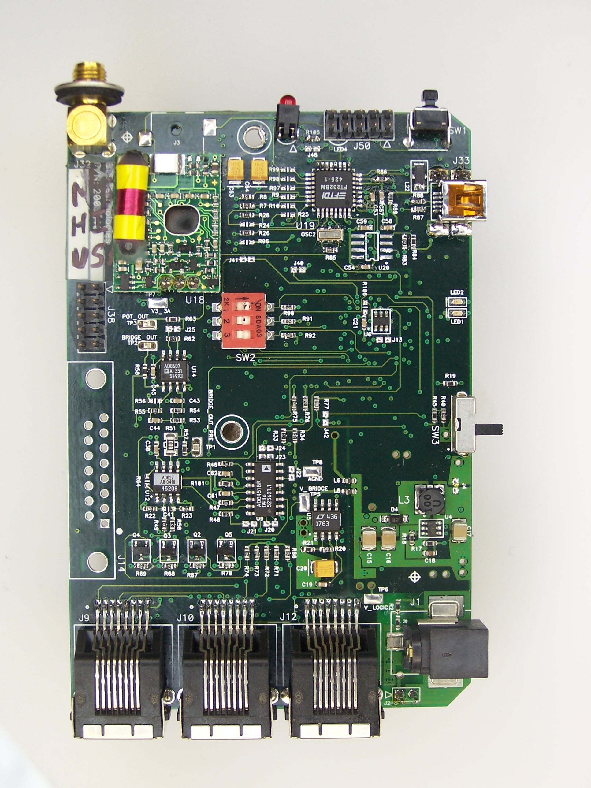
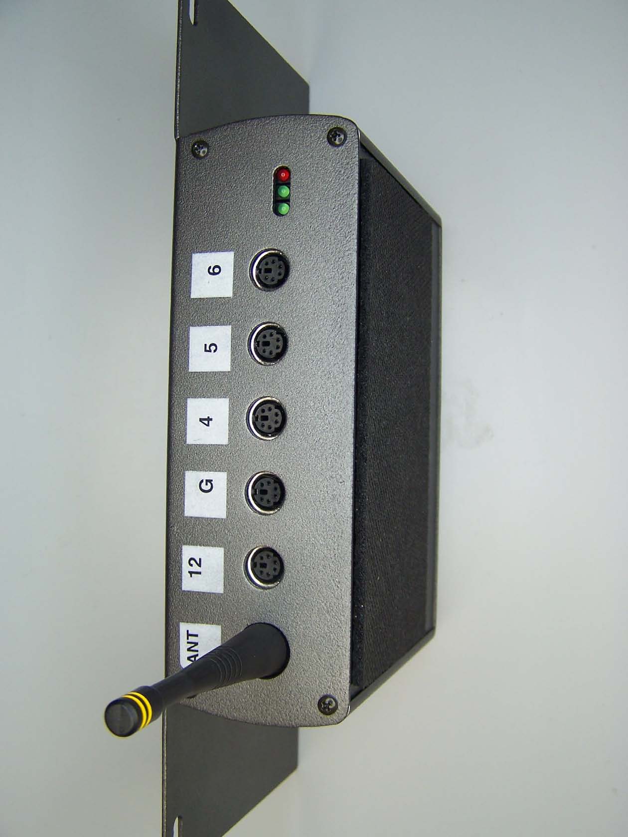
Product Description The DAQ Retrofit component from BTE Technologies is part of a larger system, the ER system. The ER system designed to capture and record human performance data. The system is designed with an assortment of sensors to measure the strength and range of motion from a test subject. The DAQ retrofit component connects a variety of force and position sensors to a PC host. In addition, it receives heart rate data from a remote transceiver (previously certified component). The DAQ Retrofit communicates with the remote heart rate transceiver on a wireless link. The RF communications are effected by an off the shelf low power radio transceiver from Radiotronix Inc. For North American applications, the transceiver operates in the 902-928 MHz band. A corresponding 868-870 MHz module is used for Europe. Data is acquired from the remote transceiver by means of a polling architecture. The DAQ Retrofit component periodically requests data from the remote transceiver. The remote transceiver encodes heart rate information and sends a response packet. The response is transferred back to the PC host.
Electromagnetic Compatibility Baltimore Therapeutic Equipment Additional Photographs DAQ Retrofit (model BTEDAQ) CFR Title 47, Part 15 Subpart C MET Report: EMC19037-FCC247 © 2006, MET Laboratories, Inc. Page 24 of 56 DOC-EMC702 2/26/2004 3.5 RF Exposure RF Exposure Requirements - § 15.247 (b) (5): Systems operating under the provisions of this section shall be operated in a manner that ensures that the public is not exposed to radio frequency energy levels in excess of the Commission’s guidelines. RF Radiation Limits: §1.1310: As specified in this section, the Maximum Permissible Exposure (MPE Limit shall be used to evaluate the environmental impact of human exposure to radiofrequency (RF) radiation as specified in Section 1.1307 (b), except in the case of portable devices which shall be evaluated according to the provisions of Section 2.1903 of this chapter. Frequency Range (MHz) Electric Field Stretgh (V/m) Magnetic Field Stregth (A/m) Power Density (mW/cm 2 ) Average Time (minutes) (A) Limits for Occupational/Control Exposures 30-300 61.4 0.163 1.0 6 300-1,500 -- -- F/300 6 1,500-100,000 -- -- 5 6 (B) Limits for General Population/Uncontrolled Exposure 30-300 27.5 0.073 0.2 30 300-1,500 -- -- F/1,500 30 1,500-100,000 -- -- 1.0 30 Table 11. Limits for Maximum Permissible Exposure Note: F=Frequency in MHz Test Results: MPE Limit Calculation: the EUT’s operating frequencies @ 902 - 928 MHz; conducted power = 12.52 dBm (peak) with maximum antenna gain of 2.7 dBi. Therefore, maximum limit for Uncontrolled exposure: 0.619 mW/ cm ² or 6.19 W/m ² Equation from page 18 of OET 65, Edition 97-01 S = PG / 4πR² P = Power Input to antenna (0.018 Watts) G = Antenna Gain (1.86 numeric) R = distance to the center of radiation of antenna (in meter) = 0.20 m S = (0.018 * 1.86)/ (4π * 0.2²) = 0.067 W/m² Therefore, at 20 cm the spectral power density is less than the 6.19 W/m² limit for uncontrolled exposure. Test Engineer: Dusmantha Tennakoon, Test Date: 02/09/2006
MET Laboratories, Inc. Safety Certification - EMI - Telecom Environmental Simulation 914 WEST PATAPSCO AVENUE ! BALTIMORE, MARYLAND 21230-3432 ! PHONE (410) 354-3300 ! FAX (410) 354-3313 The Nation’s First Licensed Nationally Recognized Testing Laboratory Baltimore Therapeutic Equipment February 17, 2006 7455-L New Ridge Road Hanover, MD 21076 Dear Joseph Perret, Enclosed is the EMC test report for compliance testing of the Baltimore Therapeutic Equipment, DAQ Retrofit (model BTEDAQ) as tested to the requirements of Title 47 of the CFR, Ch. 1 (10-1-03 ed.), Part 15 Subpart C, §15.247 for Intentional Radiators. Thank you for using the services of MET Laboratories, Inc. If you have any questions regarding these results or if MET can be of further service to you, please feel free to contact me. Sincerely yours, MET LABORATORIES, INC. Marie Confroy Documentation Department Reference: (\Baltimore Therapeutic Equipment/EMC19037-FCC247) Certificates and reports shall not be reproduced except in full, without the written permission of MET Laboratories, Inc. While use of the National Voluntary Laboratory Accreditation Program (NVLAP) letters or the NVLAP Logo, the Standards Council of Canada Logo, A2LA, or the Nationally Recognized Testing Laboratory (NRTL) Letters in this report reflects MET Accreditation under these programs, these letters, logo, or statements do not claim product endorsement by these organizations or any Agency of the U.S. Government. This letter of transmittal is not a part of the attached report. DOC-EMC702 2/26/2004 MET Laboratories, Inc. Safety Certification - EMI - Telecom Environmental Simulation 914 WEST PATAPSCO AVENUE ! BALTIMORE, MARYLAND 21230-3432 ! PHONE (410) 354-3300 ! FAX (410) 354-3313 DOC-EMC702 2/26/2004 Certificates and reports shall not be reproduced except in full, without the written permission of MET Laboratories, Inc. Electromagnetic Compatibility Test Report For the Baltimore Therapeutic Equipment DAQ Retrofit (model BTEDAQ) Tested in Accordance with Title 47 of the CFR FCC Part 15 Subpart C MET Report: EMC19037-FCC247 February 17, 2006 Prepared For: Baltimore Therapeutic Equipment 7455-L New Ridge Road Hanover, MD 21076-3105 Prepared By: MET Laboratories, Inc. 914 West Patapsco Avenue Baltimore, MD 21230 Baltimore Therapeutic Equipment DAQ Retrofit (model BTEDAQ) CFR Title 47, Part 15 Subpart C MET Report: EMC19037-FCC247 © 2006, MET Laboratories, Inc. Page i of v DOC-EMC702 2/26/2004 Electromagnetic Compatibility Test Report For the Baltimore Therapeutic Equipment DAQ Retrofit (model BTEDAQ) Tested in Accordance with Title 47 of the CFR FCC Part 15 Subpart C Dusmantha Tennakoon Marie Confroy Test Engineer, Electromagnetic Compatibility Lab Documentation Department Engineering Statement: The measurements shown in this report were made in accordance with the procedures indicated, and the emissions from this equipment were found to be within the limits applicable. I assume full responsibility for the accuracy and completeness of these measurements, and for the qualifications of all persons taking them. It is further stated that upon the basis of the measurements made, the equipment tested is capable of operation in accordance with the requirements of Part 15, §15.247 of the FCC Rules under normal use and maintenance. Kevin Mehaffey Manager, Electromagnetic Compatibility Lab Baltimore Therapeutic Equipment DAQ Retrofit (model BTEDAQ) CFR Title 47, Part 15 Subpart C MET Report: EMC19037-FCC247 © 2006, MET Laboratories, Inc. Page ii of v DOC-EMC702 2/26/2004 Report Status Sheet Revision Report Date Reason for Revision Ø February 17, 2006 Initial Issue. Baltimore Therapeutic Equipment DAQ Retrofit (model BTEDAQ) CFR Title 47, Part 15 Subpart C MET Report: EMC19037-FCC247 © 2006, MET Laboratories, Inc. Page iii of v DOC-EMC702 2/26/2004 List of Terms and Abbreviations AC Alternating Current ACF Antenna Correction Factor Cal Calibration d Measurement Distance dB Deci Bels dBFV Deci-Bels above one micro Volt dBFV/m Deci-Bels above one micro Volt per meter DC Direct Current DCF Distance Correction Factor E Electric Field EUT Equipment Under Test f Frequency FCC Federal Communications Commission H Magnetic Field GHz Giga Hertz Hz Hertz ICES Interference-Causing Equipment Standard kHz kilohertz kPa kilopascal kV kilo Volt LISN Line Impedance Stabilization Network MHz MegaHertz FH micro Henry FF micro Farad Fs micro seconds RF Radio Frequency RMS Root-Mean-Square Baltimore Therapeutic Equipment Table of Contents DAQ Retrofit (model BTEDAQ) CFR Title 47, Part 15 Subpart C MET Report: EMC19037-FCC247 © 2006, MET Laboratories, Inc. Page iv of vi DOC-EMC702 2/26/2004 Table of Contents 1 Introduction ...................................................................................................................................................................... 1 1.1 Overview ...................................................................................................................................................................... 1 1.2 Test Site........................................................................................................................................................................ 1 1.3 Testing Summary ......................................................................................................................................................... 2 2 Equipment Configuration................................................................................................................................................ 3 2.1 Description of EUT ...................................................................................................................................................... 3 2.2 Equipment Configuration............................................................................................................................................. 3 2.3 Support Equipment.........................................…
Text truncated - open the document above for the full version.
| # | Rule Parts | Frequency Range | Power Output |
|---|---|---|---|
| 1 | 15C | 902.7 MHz - 926.05 MHz | 18.00 mW |

MCU Wireless
Equipment Class
DTS - Digital Transmission System