FCCID.CO- FCC ID Database
HomeCompaniesEquipment ClassesSearch

© 2026 FCC ID Database. All rights reserved.

AboutContactData sourced from FCC public records
  1. Home/
  2. BTE Technologies, Inc./
  3. TV3WER-1

TV3WER-1MCU Wireless

BTE Technologies, Inc.
MCU Wireless - FCC ID TV3WER-1 - BTE Technologies, Inc.
Click to zoom

Application Details

Equipment Class
DTS - Digital Transmission System
Date of Grant
Mar 23, 2006
Application Purpose
Original Equipment
Date of Application
Mar 23, 2006
Equipment Note
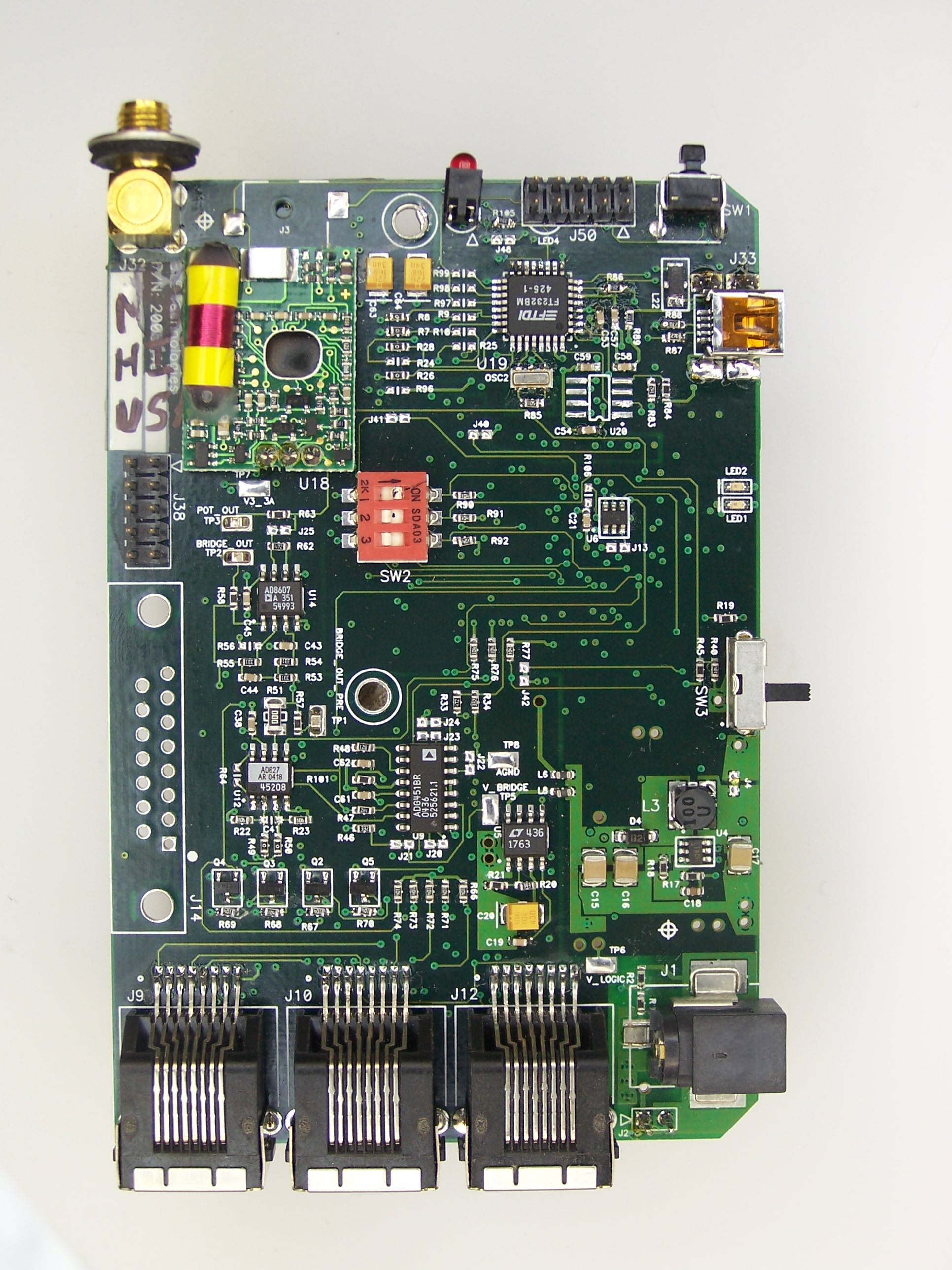
MCU Wireless
Frequency Range
903.00000000 - 926.30000000
Company
BTE Technologies, Inc.
Country
United States

Documents & Files

Select a file to view

Users Manual

↗
↗

Attestation Statements

↗
↗
↗
↗
↗

Cover Letter(s)

↗
↗
↗
↗
↗
↗

External Photos

↗

ID Label/Location Info

↗
↗
↗

Internal Photos

↗

Operational Description

↗
↗
↗
↗
↗

Schematics

↗

Test Report

↗

Test Setup Photos

↗

Document Text

Text extracted from the exhibit documents filed with the FCC. Open a document above to read the original.

Users Manual

section 01 page 7 40040005 rev. 000 2. PRINTER Remove the printer from its box and place it on the 2 nd shelf of the computer cart. Fol- lowing the instructions from the printer box, insert the ink cartridges and plug in the power cord and USB cable. Once the computer is running and the printer is turned on, print a test page. 3. CPU Remove the CPU (computer tower) from its box and place it on the 3 rd shelf of the com- puter cart. Plug in the power cord, monitor serial cable, and printer USB cable. 4. SPEAKERS Remove the speakers from their box and place them on the 3 rd shelf of the computer cart. Plug the cable from the left speaker into the designated jack on the right speaker. Next, plug the power cord into the designated jack on the right speaker. Finally, plug the speaker cable, which is attached to the right speaker into the CPU. 5. KEYBOARD & MOUSE Remove the keyboard and mouse from their box. Place the keyboard on the auxiliary shelf of the computer cart and plug the cord into the CPU. Place the mouse on the top shelf of the computer cart and plug the cord into the CPU. 6. WIRELESS HUB Locate the wireless Hub and place it on the 2 nd shelf of the computer cart. Note that inside of the Hub are magnets, which are intended to keep the Hub stable on the shelf. Secure the 2 nd antenna (from Step 6 of ‘Setting up the MCU Station’) to the Hub (Figure 1-12). Plug the USB cable into the CPU. Note that is important to store the Hub in a location such that its antenna is at least 3 feet from the antenna at the top of the MCU. 7. ISOLATION TRANSFORMER Locate the isolation transformer and its power cord and place it next to the designated wall outlet. Attach the computer cart cable, which is located at the bottom back of the cart, to the isolation transformer. Plug one end of the isolation transformer power cord into the isolation transformer and the other end into the designated wall outlet. Turn on the isolation transformer via the green switch (Figure 1-13). Figure 1-12. Place- ment of Hub Figure 1-13. Place- ment of Transformer The use of extension cords is not recommended. If an extension cord cannot be avoid- ed, use no less than 14 gauge wire. Keep the cord as short as possible, and use only hospital approved plugs. The extension cord MUST complete the ground from the ER power supply cord to the wall outlet.

Users Manual

40040005 rev. 000 USER MANUAL 40040005 rev. 000 40040005 rev. 000 Copyright 2005 BTE Technologies All Rights Reserved Information in this document is subject to change without notice. Companies, names and data used in examples are fictitious unless otherwise noted. No part of this manual may be reproduced or transmitted in any form or by any means electronic, mechanical, or otherwise, including photocopying and recording or in connection with any information storage and retrieval system, without prior permission from BTE Technologies. BTE Technologies, Inc.™ may have patents or pending patent applications, trademarks copyrights or other intellectual property rights covering subject matter in this document. The furnishing of this document does not give you license to these patents, trademarks, copyrights, or other intellectual property except as expressly provided in any written license agreement from BTE Technologies, Inc.™ Printed in the U.S.A. This manual supports the BTE Multi-Cervical™ Unit Rev. 000 BTE Technologies 7455-L New Ridge Road Hanover, MD 21076 Phone: 410.850.0333 Toll Free: 800.331.8845 Fax: 410.850.5244 [email protected] www.BTEtech.com 40040005 rev. 000 Warranty We guarantee that the BTE Technologies, Inc. rehabilitation products are free of manufacturer defects in both workmanship and material. We will replace or repair defective parts or equipment for a period of time and in accordance with the conditions set forth below: This warranty covers the structure and framework for 1 year of normal institutional use. All mechanical components including bearings, bushings, pulleys and glides are warranted from manufacturer defects in both workmanship and material for a one-year period. Cords and padding are covered for a 1-year period under normal use. This limited warranty is in lieu of all warranties, expressed or implied and all other obligations or liabilities on the part of BTE Technologies Inc. We neither assume nor authorize any person to assume any other obligation or liability in connection with the sale of this product. Under no circumstances shall BTE Technologies, Inc. be liable by virtue of this warranty or otherwise, for damage to any person or property what so ever for any special, indirect, secondary or consequential damage of any nature however arising out of the use or inability to use this product. This limited warranty applies only while the BTE Technologies, Inc. product remains in the possession of the original purchaser and has not been subject to accident, misuse, abuse, unauthorized modification, failure to follow instructional use, failure to do proper maintenance, incorrect adjustments or failure due to cause beyond the manufacture’s control. Disclaimer The information presented in this manual is given in good faith and is to the best of our knowledge accurate. However, anyone who uses this information in any way does so entirely at his or her own risk. Neither BTE Technologies, Inc., its officers nor their representatives can accept any responsibility for any damage or injury incurred as a result of information presented here except under the terms of the product warranty. Class A Digital Device This equipment has been tested and found to comply with the limits for a Class A digital device, pursuant to part 15 of the FCC Rules. These limits are designed to provide reasonable protection against harmful interference when the equipment is operated in a commercial environment. This equipment generates, uses, and can radiate radio frequency energy and, if not installed and used in accordance with the instruction manual, may cause harmful interference to radio communications. Operation of this equipment in a residential area is likely to cause harmful interference in which case the user will be required to correct the interference at his own expense. 40040005 rev. 000 01 - Installation and Setup 02 - General Operation 03 - Client Information 04 - Templates 05 - Calibration 06 - Protocols 07 - Reports 08 - Cervical Conditioning 09 - Maintenance 10 - The Melbourne Protocol USER MANUAL section 01 page 1 40040005 rev. 000 01 - INSTALLATION & SETUP Introduction 3 MCU™ Components 3 Multi-Cervical ™ Station 3 Calibration Tools 4 Computer Equipment and Cart 4 Assembly Instructions 4 Setting up the MCU ™ Station 4 Setting up the Computer Equipment and Cart 6 Strongly Recommended Additional Purchases 7 Computer Care 7 Check Computer Cables 7 Environment Requirements 7 page 2 section 01 40040005 rev. 000 section 01 page 3 40040005 rev. 000 INSTALLATION AND SETUP I. INTRODUCTION When you first look at the MCU™, it may be difficult to imagine that a cervical assessment can be so simple. However, once you familiarize yourself with the basic components of the unit and practice its operation following appropriate training, you will wonder how you ever did assess- ments without it. This MCU™ Operator’s Manual will review the basic components of the Multi Cervical™ Unit. Once you are familiar with the components, you can explore the techniques and protocols for performing a cervical assessment, including range of motion and isometric strength testing. This Manual will also review the different types of reports that are automatically generated using the information acquired throughout the assessment, as well as the clinical documenta- tion you provide the Objective Documentation Evaluation System (ODES™) computer diagnostic system component. BTE Technologies recommends that the Multi-Cervical™ Unit be used in conjunction with a cer- tified training program on The Melbourne Protocol. Two-day comprehensive training programs are tailored to suit the specific needs of your facility. Refer to Section 10 for more information. II. MCU™ COMPONENTS A. MULTI CERVICAL™ STATION The Multi Cervical™ Station consists of the base, column with weight stack, seat, halo, weight stack pins, ROM stop, (2) head braces, (3) Velcro straps, and (4) RJ45 cables - 2 short and 2 long (Figure 1-1). F…

Text truncated - open the document above for the full version.

Attestation Statements

section 01 page 3 40040005 rev. 000 INSTALLATION AND SETUP I. INTRODUCTION When you first look at the MCU™, it may be difficult to imagine that a cervical assessment can be so simple. However, once you familiarize yourself with the basic components of the unit and practice its operation following appropriate training, you will wonder how you ever did assess- ments without it. This MCU™ Operator’s Manual will review the basic components of the Multi Cervical™ Unit. Once you are familiar with the components, you can explore the techniques and protocols for performing a cervical assessment, including range of motion and isometric strength testing. This Manual will also review the different types of reports that are automatically generated using the information acquired throughout the assessment, as well as the clinical documenta- tion you provide the Objective Documentation Evaluation System (ODES™) computer diagnostic system component. BTE Technologies recommends that the Multi-Cervical™ Unit be used in conjunction with a cer- tified training program on The Melbourne Protocol. Two-day comprehensive training programs are tailored to suit the specific needs of your facility. Refer to Section 10 for more information. II. MCU™ COMPONENTS A. MULTI CERVICAL™ STATION The Multi Cervical™ Station consists of the base, column with weight stack, seat, halo, weight stack pins, ROM stop, (2) head braces, (3) Velcro straps, and (4) RJ45 cables - 2 short and 2 long (Figure 1-1). Figure 1-1. Multi-Cervical TM Station Head Braces Velcro Straps RJ45 Cables Base Seat Column Halo Weight Stack Pins & ROM Stop DO NOT CHANGE OR MODIFY ANY COMPONENTS Any changes or modifications, especially to the wireless components, not expressly approved by BTE Technologies, Inc. could void the user’s authority to operate the equipment.

Attestation Statements

40040005 rev. 000 Warranty We guarantee that the BTE Technologies, Inc. rehabilitation products are free of manufacturer defects in both workmanship and material. We will replace or repair defective parts or equipment for a period of time and in accordance with the conditions set forth below: This warranty covers the structure and framework for 1 year of normal institutional use. All mechanical components including bearings, bushings, pulleys and glides are warranted from manufacturer defects in both workmanship and material for a one-year period. Cords and padding are covered for a 1-year period under normal use. This limited warranty is in lieu of all warranties, expressed or implied and all other obligations or liabilities on the part of BTE Technologies Inc. We neither assume nor authorize any person to assume any other obligation or liability in connection with the sale of this product. Under no circumstances shall BTE Technologies, Inc. be liable by virtue of this warranty or otherwise, for damage to any person or property what so ever for any special, indirect, secondary or consequential damage of any nature however arising out of the use or inability to use this product. This limited warranty applies only while the BTE Technologies, Inc. product remains in the possession of the original purchaser and has not been subject to accident, misuse, abuse, unauthorized modification, failure to follow instructional use, failure to do proper maintenance, incorrect adjustments or failure due to cause beyond the manufacture’s control. Disclaimer The information presented in this manual is given in good faith and is to the best of our knowledge accurate. However, anyone who uses this information in any way does so entirely at his or her own risk. Neither BTE Technologies, Inc., its officers nor their representatives can accept any responsibility for any damage or injury incurred as a result of information presented here except under the terms of the product warranty. Class A Digital Device This equipment has been tested and found to comply with the limits for a Class A digital device, pursuant to part 15 of the FCC Rules. These limits are designed to provide reasonable protection against harmful interference when the equipment is operated in a commercial environment. This equipment generates, uses, and can radiate radio frequency energy and, if not installed and used in accordance with the instruction manual, may cause harmful interference to radio communications. Operation of this equipment in a residential area is likely to cause harmful interference in which case the user will be required to correct the interference at his own expense.

Attestation Statements

section 01 page 5 40040005 rev. 000 Step 2. Locate the weight stack pins and ROM stop pin and place them in the correspond- ing holes on the calibration plate (Figure 1-5). Step 3. Locate the head braces and secure them to the calibra- tion plate (Figure 1-6). Step 4. Locate the Velcro straps and RJ45 cables. These may be placed on the computer cart. Step 5. Locate the calibration weights and calibration block and place them in the triangular bracket on the base (Figure 1-7). Step 6. Locate the 2 antennas and then locate the far- right hole on the top back of the MCU™ station. Insert one of the antennas through this hole and secure it to the PCB (Figure 1-8). Figure 1-5. Location of Weight Stack Pins & ROM STop Pin Figure 1-6. Head Braces Secured to Column Figure 1-7. Location of Calibration Tools Figure 1-8. Attaching the Antenna ACCEPTABLE ANTENNA(S) This device has been designed to operate with the antenna(s) listed below and having a maximum gain of 2.7 dBi. Antennas not included in this list or having a gain greater than 2.7 dBi are strictly prohibited for use with this device. The required antenna im- pedance is 50 ohms. Acceptable antenna(s) include: 1. Linx Technologies 916MHz 1/4 Wave Whip Antenna (ANT-916-CW-QW) To reduce potential radio interference to other users, the antenna type and its gain should be so chosen that the equivalent isotropically radiated power (e.i.r.p.) is not more than that permitted for successful communication.

Attestation Statements

page 4 section 09 III. PREVENTION OF INTERFERENCE BETWEEN WIRELESS COMPONENTS Interference, which can result in an inability to acquire accurate data, may occur in the follow- ing scenarios: a. There are multiple wireless systems within 50 feet of each other that are on the same wireless channel (e.g. 2 wireless ERs in the same clinic on channel 16). b. The antennas of any wireless components are within 3 feet of each other (e.g. the an- tenna on the Hub is within 3 feet of the antenna on the top slider of the ER Column). c. There is not a direct line of sight between the antennas of the wireless components. In addition, any metal that is between the antennas will cause interference. You may prevent interference by maintaining your system in the following manner: a. Do not allow the Hub to fall on the floor; there are magnets inside the Hub that will aid in securing it to the computer cart. b. Regularly check the USB cable that is attached to the Hub and check the power cable that is attached to the ER column. c. Verify the antennas are in good working order and properly secured. d. Verify there are freshly-charged batteries in the Hip unit. You may also prevent interference by using the following guidelines: a. If there are multiple wireless systems within 50 feet of each, verify that each unit is on a different wireless channel. Refer to Section 02-IV-C-4 (URFIO Configuration Applica- tion) for how to determine on which channel a system is operating. b. The recommended location for the Hub is on the second shelf of the computer cart. This helps to ensure the antenna of the Hub will be at least 3 feet from the antenna on the ER column. In addition, be wary of where the Hip unit is with respect to the Hub, espe- cially if the Hip unit is secured to a patient who is moving around the system. c. Verify there is a direct line of sight between: 1) the Hub antenna and the ER column an- tenna and 2) the Hub antenna and the Hip antenna.

Attestation Statements

page 4 section 09 40040005 rev. 000 B. MAINTENANCE SCHEDULE 1. AFTER EACH CLIENT • Clean the head braces and arm rests with an antibacterial wipe or rubbing alcohol (70% alcohol). Make sure to not allow any liquid to enter the RJ45 jacks on the head braces or the top of the column. 2. DAILY • Verify any equipment that has been calibrated. If verification fails, then recalibrate the tool • Clean the halo with an antibacterial wipe or rubbing alcohol (70% alcohol) • Clean the seat bottom and back with an antibacterial wipe or rubbing alcohol (70% alcohol) 3. WEEKLY • Calibrate and verify all tools 4. MONTHLY • Check all the cables to ensure they are secure and in good working condition III. PREVENTION OF INTERFERENCE BETWEEN WIRELESS COMPONENTS Interference, which can result in an inability to acquire accurate data, may occur in the follow- ing scenarios: a. There are multiple wireless systems within 50 feet of each other that are on the same wireless channel (e.g. 2 wireless MCUs in the same clinic on channel 16). b. The antennas of any wireless components are within 3 feet of each other (e.g. the an- tenna on the Hub is within 3 feet of the antenna on top of the MCU). c. There is not a direct line of sight between the antennas of the wireless components. In addition, any metal that is between the antennas will cause interference. You may prevent interference by maintaining your system in the following manner: a. Do not allow the Hub to fall on the floor; there are magnets inside the Hub that will aid in securing it to the computer cart. b. Regularly check the USB cable that is attached to the Hub and check the power cable that is attached to the MCU. c. Verify the antennas are in good working order and properly secured. You may also prevent interference by using the following guidelines: a. If there are multiple wireless systems within 50 feet of each, verify that each unit is on a different wireless channel. Refer to Section 02-IV-C-4 (URFIO Configuration Applica- tion) for how to determine on which channel a system is operating. b. The recommended location for the Hub is on the second shelf of the computer cart. This ensures the antenna of the Hub will always be at least 3 feet from the antenna on the top of the MCU. c. Verify there is a direct line of sight between the Hub antenna and the MCU antenna.

Cover Letter(s)

BTE Technologies, Inc. – Products Group BTE Technologies, Inc. – Employer/Payer Services 7455-L New Ridge Road – Hanover, MD 21075 8390 E. Crescent Parkway, Suite 120 – Greenwood Village, CO 800-331-8445 410-850-0333 800-206-2972 720-266-0120 Attn: Reviewing Engineer Federal Communications Commission 7435 Oakland Mills Road Columbia, MD 21046 RE: LETTER OF AGENT AUTHORIZATION To Whom It May Concern: We, the undersigned, hereby authorize MET Laboratories, Inc. to act on our behalf in all matters relating to application for equipment authorization, including the signing of all documents relating to these matters. We also hereby certify that no party to the application authorized hereunder is subject to the denial of benefits, including FCC benefits, pursuant to Section 5301 of the Anti-Drug Abuse Act of 1988, 21 U.S.C.853(a). This agreement expires one year from the current date. Sincerely, Joseph Perret, VP Engineering

Cover Letter(s)

BTE Technologies, Inc. – Products Group BTE Technologies, Inc. – Employer/Payer Services 7455-L New Ridge Road – Hanover, MD 21075 8390 E. Crescent Parkway, Suite 120 – Greenwood Village, CO 800-331-8445 410-850-0333 800-206-2972 720-266-0120 January 25, 2006 Confidentiality is not requested for the WER-1 modular product approval. Joseph Perret VP Engineering

Cover Letter(s)

BTE Technologies, Inc. – Products Group BTE Technologies, Inc. – Employer/Payer Services 7455-L New Ridge Road – Hanover, MD 21075 8390 E. Crescent Parkway, Suite 120 – Greenwood Village, CO 800-331-8445 410-850-0333 800-206-2972 720-266-0120 March 6,2006 The purpose of this letter is to outline the different versions of the WER-1 module. The WER-1 module exists in four different versions. Internally, they are named HIP, HUB, MCU, and COLUMN. All four versions use the same circuit board. The difference between modules is the population of components on the board. All versions include the RF transceiver and microcontroller. The various versions have differences in installed connectors and analog circuitry. For testing purposes, a super-populated sample was used. This sample included all components from all versions. This is not a production configuration, but it means that all production versions are de-populated versions of the test sample.

Cover Letter(s)

BTE Technologies, Inc. – Products Group BTE Technologies, Inc. – Employer/Payer Services 7455-L New Ridge Road – Hanover, MD 21075 8390 E. Crescent Parkway, Suite 120 – Greenwood Village, CO 800-331-8445 410-850-0333 800-206-2972 720-266-0120 March 14,2006 The purpose of this letter is to request modular approval for the WER-1 module. Compliance with the requirements is documented below. 1. The modular transmitter must have its own RF shielding. • Metal shielding is evident in pictures of the device. The shield covers the RF transceiver circuitry. 2. The modular transmitter must have buffered modulation/data inputs (if such inputs are provided) to ensure that the module will comply with Part 15 requirements under conditions of excessive data rates or over-modulation. • Yes it has buffered inputs. Please see the device schematic. 3. The modular transmitter must have its own power supply regulation. • Yes the module has its own power supple regulation. Please see the device schematic. 4. The modular transmitter must comply with the antenna requirements of Section 15.203 and 15.204(c). • The antenna uses a reverse polarity SMA scheme. 5. The modular transmitter must be tested in a stand-alone configuration, i.e., the module must not be inside another device during testing. • The device was tested in a stand alone configuration. 6. The modular transmitter must be labeled with its own FCC ID number, and, if the FCC ID is not visible when the module is installed inside another device, then the outside of the device into which the module is installed must also display a label referring to the enclosed module. • Photographs have been submitted showing marking on the module as well as on the module enclosures. 7. The modular transmitter must comply with any specific rule or operating requirements applicable to the transmitter and the manufacturer must provide adequate instructions along with the module to explain any such requirements. • Users are unable to change transmitter settings. 8. The modular transmitter must comply with any applicable RF exposure requirements. • The 902-928 MHz device has a conducted power of 25.5mW and has an antenna gain of 2.7dBi. The total radiated power (EIRP) is less than the TCB Exclusion Low Threshold (calculated to be 66mW) and therefore RF exposure testing (SAR or MPE) is not required. This device has no restriction for mobile or portable use.

ID Label/Location Info

FCC / IC label placement A mock label is shown in the photographs show label placement on the equipment. Production labels will be printed as shown on drawing 14050427. MCU placement – back of equipment cabinet near the antenna. ER column placement – at the top, rear of the column assembly Hip transmitter placement – adjacent to the belt clip. Hub transmitter placement – on the bottom side of the enclosure.

ID Label/Location Info

FCCID: TV3WER-1 IC: 6269A-WER1 FCCID: TV3WER-1 IC: 6269A-WER1 Hub URFIO: MCU/Hip/Column Mount URFIO: FCCID: TV3WER-1 IC: 6269A-WER1 FCCID: TV3WER-1 IC: 6269A-WER1

ID Label/Location Info

11 22 A A B B SIZE DWG NO REV SCALE SHEET OF TITLE A NICOLAISEN 12/29/05 XXXX XX-XX-XX DRAFTERCHECKED 7455-L NEW RIDGE ROADHANOVER, MD 21076 LABEL, CERTIFICATIONS,ER II/MCU 2 A 14050427 000 NTS 1 1 TOLERANCES UNLESS SPECIFIED FRACTION OR .X ` 1/32 .XX ` .01 .XXX ` .005 ANGULAR ` 1 ~ DIMENSIONS IN [ ] ARE METRIC SPECIFICATIONS NOTED NOTES: A) MATL: 8200HD/830 0C/GL - METALIZED POLYESTER WITH HEAVY DUTY ADHESIVE & CLEAR GLOSS OVER LAMINATE REVISION HISTORY REV DESCRIPTION DATE APPROVED ECO 000 NEW DRAWING 12/29/05 ATN Contains Transmitter with FCCID: TV3WER-1 IC: 6269A-WER1 2.50 1.00

Operational Description

section 01 page 7 40040005 rev. 000 2. PRINTER Remove the printer from its box and place it on the 2 nd shelf of the computer cart. Fol- lowing the instructions from the printer box, insert the ink cartridges and plug in the power cord and USB cable. Once the computer is running and the printer is turned on, print a test page. 3. CPU Remove the CPU (computer tower) from its box and place it on the 3 rd shelf of the com- puter cart. Plug in the power cord, monitor serial cable, and printer USB cable. 4. SPEAKERS Remove the speakers from their box and place them on the 3 rd shelf of the computer cart. Plug the cable from the left speaker into the designated jack on the right speaker. Next, plug the power cord into the designated jack on the right speaker. Finally, plug the speaker cable, which is attached to the right speaker into the CPU. 5. KEYBOARD & MOUSE Remove the keyboard and mouse from their box. Place the keyboard on the auxiliary shelf of the computer cart and plug the cord into the CPU. Place the mouse on the top shelf of the computer cart and plug the cord into the CPU. 6. WIRELESS HUB Locate the wireless Hub and place it on the 2 nd shelf of the computer cart. Note that inside of the Hub are magnets, which are intended to keep the Hub stable on the shelf. Secure the 2 nd antenna (from Step 6 of ‘Setting up the MCU Station’) to the Hub (Figure 1-12). Plug the USB cable into the CPU. Note that is important to store the Hub in a location such that its antenna is at least 3 feet from the antenna at the top of the MCU. 7. ISOLATION TRANSFORMER Locate the isolation transformer and its power cord and place it next to the designated wall outlet. Attach the computer cart cable, which is located at the bottom back of the cart, to the isolation transformer. Plug one end of the isolation transformer power cord into the isolation transformer and the other end into the designated wall outlet. Turn on the isolation transformer via the green switch (Figure 1-13). Figure 1-12. Place- ment of Hub Figure 1-13. Place- ment of Transformer The use of extension cords is not recommended. If an extension cord cannot be avoid- ed, use no less than 14 gauge wire. Keep the cord as short as possible, and use only hospital approved plugs. The extension cord MUST complete the ground from the ER power supply cord to the wall outlet.

Operational Description

Product Description The MCU and ER family of systems from BTE Technologies are designed to capture and record human performance data. Both systems are designed with an assortment of sensors to measure the strength and range of motion from a test subject. The MCU is more specifically focused on the muscles and joints of the cervical spine. The ER is more general in purpose and measures pushing, pulling, and lifting forces. The Evaluator and Cires are sub-products in the ER line. They include only a portion of the tools and sensors of the ER product. All of these products use a common wireless data acquisition system. The RF communications are effected by an off the shelf low power radio transceiver from Radiotronix Inc. For North American applications, the transceiver operates in the 902- 928 MHz band. A corresponding 868-870 MHz module is used for Europe. The data acquisition system has a polling architecture. A central data hub requests data from the collection modules in the vicinity. The collection modules encode data from the various sensors and transmit the data back to the hub. Each sensor is individually addressable. Typically only one sensor will be read at a time to minimize packet size and RF traffic.

Operational Description

ZONEREVDESCRIPTIONDATE APPROVED LINX TECHNOLOGIES 575 S.E. Ashley, Pl. Grants Pass, OR 97526 PHONE: 541-471-6256 FAX: 541-471-6251 www.linxtechnologies.com SIZE A FSCM NO.DWG NO. DESIGN: DRAWING: Chris APPROVED: SERIES NUMBER STATUS: DRAFT/APPROVED DATE: 5/15/98 PAT H PART NUMBER SHEET SCALE Covers Part #s 2.03" (52) Ø0.30" (7.8) 0.50" (13) 6.94" (178) - 418 MHz 6.75" (173) - 433 MHz 868 MHz 1 3.13" (80) - 916 MHz End View 0.18" (4.5) 0.57" (14.5) 0.25" (6.4) RPSMA 315 MHz = ANT-315-CW-QW 418 MHz = ANT-418-CW-QW 433 MHz = ANT-433-CW-QW Threads common to ground CONNECTORIZED 1/4-WAVE WHIP ANTENNAS CH1 S 11 SWR1 / REF 1 SPAN = 650 MHz 1 MARKER 1 hp 1: 1.0363 Marker 1 = Specified Frequency 1 -5.3926 Ω 70.607 pF CH1 S 11 1: 51.189 Ω SPAN = 50 MHz Marker 1 = Specified Center Frequency

Operational Description

BTE Technologies, Inc. – Products Group BTE Technologies, Inc. – Employer/Payer Services 7455-L New Ridge Road – Hanover, MD 21075 8390 E. Crescent Parkway, Suite 120 – Greenwood Village, CO 800-331-8445 410-850-0333 800-206-2972 720-266-0120 Module Description The WER-1 module is a component of a data acquisition system. The same module can serve as both hub and client. There are three elements to the module; RF transceiver, micro- controller, and data acquisition. When configured as a hub, only the RF transceiver is used. In the hub mode, the module acts as a serial repeater. Messages from the host PC application program are transmitted. Received replies are passed back to the host PC. In the client mode, the device is idle and waits for communication from a hub module. The hub broadcasts periodic messages to detect the presence of client modules. The RF transceiver passes received messages to the micro-controller for processing. If the message was recognized, an appropriate reply will be returned to the RF transceiver for transmission back to the hub module. Most communication to the client modules are requests for data. These messages are again pass…

Text truncated - open the document above for the full version.

Contact Information

Applicant

Joseph Perret(VP of Engineering)
[email protected]410-850-0333Fax: 410-850-5244

Test Firm

MET Laboratories, Inc.Robert Frier
[email protected]4103543300Fax: 4103543313

Technical Specifications

#Rule PartsFrequency RangePower Output
115C903 MHz - 926.3 MHz25.50 mW
Modular Type
Single Modular Approval
Confidentiality
Long Term
Grant Notes
Modular Approval. Output Power listed is conducted. End-users must be informed of the operating requirements for satisfying RF exposure compliance.

Other Applications from BTE Technologies, Inc.
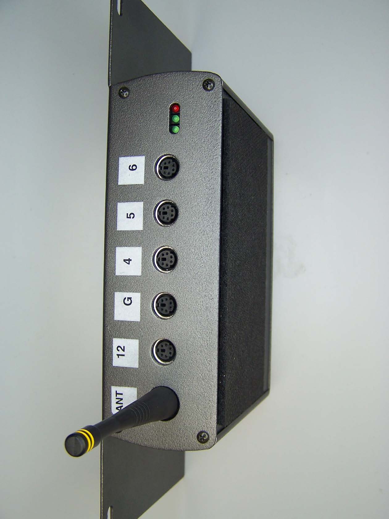
Strength measurement equipment. - FCC ID TV3DAQRETROFIT - BTE Technologies, Inc.
TV3DAQRETROFIT

Strength measurement equipment.

Feb 26, 2006

Equipment Class

DTS - Digital Transmission System