TVE3045FORTIWIFI-50B
Fortinet Inc.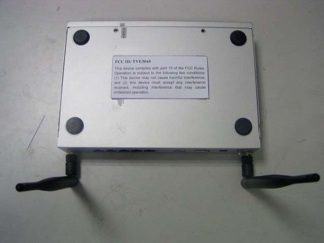
Click to zoom
Application Details
- Equipment Class
- DTS - Digital Transmission System
- Date of Grant
- Jun 13, 2007
- Application Purpose
- Original Equipment
- Date of Application
- Jun 13, 2007
- Equipment Note
- FORTIWIFI-50B
- Frequency Range
- 2412.00000000 - 2462.00000000
- Company
- Fortinet Inc.
- Country
- United States
Documents & Files
Document Text
Text extracted from the exhibit documents filed with the FCC. Open a document above to read the original.
Users Manual
www.fortinet.com FortiGate-50A/50B, FortiWiFi-50B and FortiGate-100 FortiOS 3.0 MR4 INSTALL GUIDE FortiGate-50A/50B, FortiWiFi-50B and FortiGate-100 Install Guide FortiOS 3.0 MR4 22 May 2007 01-30004-0265-20070522 © Copyright 2007 Fortinet, Inc. All rights reserved. No part of this publication including text, examples, diagrams or illustrations may be reproduced, transmitted, or translated in any form or by any means, electronic, mechanical, manual, optical or otherwise, for any purpose, without prior written permission of Fortinet, Inc. Trademarks Dynamic Threat Prevention System (DTPS), APSecure, FortiASIC, FortiBIOS, FortiBridge, FortiClient, FortiGate, FortiGate Unified Threat Management System, FortiGuard, FortiGuard-Antispam, FortiGuard- Antivirus, FortiGuard-Intrusion, FortiGuard-Web, FortiLog, FortiAnalyzer, FortiManager, Fortinet, FortiOS, FortiPartner, FortiProtect, FortiReporter, FortiResponse, FortiShield, FortiVoIP, and FortiWiFi are trademarks of Fortinet, Inc. in the United States and/or other countries. The names of actual companies and products mentioned herein may be the trademarks of their respective owners. Regulatory compliance FCC Class A Part 15 CSA/CUS ! Caution: Risk of Explosion if Battery is replaced by an Incorrect Type. Dispose of Used Batteries According to the Instructions. Contents FortiGate-50A/50B, FortiWiFi-50B and FortiGate-100 FortiOS 3.0 MR4 Install Guide 01-30004-0265-200705223 Contents Contents.............................................................................................. 3 Introduction ........................................................................................ 7 About the FortiGate unit ................................................................................... 7 FortiGate-50A................................................................................................ 7 FortiGate-50B................................................................................................ 8 FortiWiFi-50B ................................................................................................ 8 FortiGate-100 ................................................................................................ 8 Register your FortiGate unit .......................................................................... 8 Fortinet Family Products .................................................................................. 9 FortiGuard Subscription Services ................................................................. 9 FortiClient ...................................................................................................... 9 FortiMail ........................................................................................................ 9 FortiAnalyzer ............................................................................................... 10 FortiReporter ............................................................................................... 10 FortiBridge................................................................................................... 10 FortiManager ............................................................................................... 10 About this document....................................................................................... 10 Document conventions................................................................................ 11 Typographic conventions...................................................................... 11 Fortinet documentation .................................................................................. 12 Fortinet Tools and Documentation CD ........................................................ 13 Fortinet Knowledge Center ........................................................................ 13 Comments on Fortinet technical documentation ........................................ 13 Customer service and technical support ...................................................... 13 Installing the FortiGate unit ............................................................ 15 Package Contents............................................................................................ 15 FortiGate-50A.............................................................................................. 15 FortiGate-50B.............................................................................................. 16 FortiWiFi-50B .............................................................................................. 17 FortiGate-100 .............................................................................................. 17 Warnings ..................................................................................................... 18 Mounting........................................................................................................... 19 Powering on the FortiGate unit ...................................................................... 19 Power over Ethernet ................................................................................... 20 Powering off the FortiGate unit ...................................................................... 20 FortiGate-50A/50B, FortiWiFi-50B and FortiGate-100 FortiOS 3.0 MR4 Install Guide 401-30004-0265-20070522 Contents Connecting to the FortiGate unit ................................................................... 20 Web-based manager .................................................................................. 21 Command line interface .............................................................................. 21 Connecting to the web-based manager ...................................................... 21 Command line interface .............................................................................. 22 Connecting to the CLI ................................................................................. 23 Quick installation using factory defau…
Text truncated - open the document above for the full version.
Users Manual
Configuring the FortiGate unit NAT/Route mode installation FortiGate-50A/50B, FortiWiFi-50B and FortiGate-100 FortiOS 3.0 MR4 Install Guide 01-30004-0265-2007052241 config system dns set primary <address_ip> set secondary <address_ip> end Example config system dns set primary 293.44.75.21 set secondary 293.44.75.22 end Adding a default route Add a default route to configure where the FortiGate unit sends traffic that should be sent to an external network (usually the Internet). Adding the default route also defines which interface is connected to an external network. The default route is not required if the interface connected to the external network is configured using DHCP or PPPoE. To add a default route Set the default route to the Default Gateway IP address. Enter: config router static edit <seq_num> set dst <class_ip&net_netmask> set gateway <gateway_IP> set device <interface> end Verify the connection To verify the connection, try the following: • ping the FortiGate unit • browse to the web-based manager GUI • retrieve or send email from your email account If you cannot browse to the web site or retrieve/send email from your account, review the previous steps to ensure all information was entered correctly and try again. You are now finished the initial configuration of the FortiGate unit. Example If the default gateway IP is 10.10.1.2 and this gateway is connected to the external interface: config router static edit 1 set dst 0.0.0.0 0.0.0.0 set gateway 10.10.1.2 set device external end 100 50B WiFi-50B FortiGate-50A/50B, FortiWiFi-50B and FortiGate-100 FortiOS 3.0 MR4 Install Guide 4201-30004-0265-20070522 NAT/Route mode installationConfiguring the FortiGate unit Connecting the FortiGate unit to the network(s) When you have completed the initial configuration, you can connect the FortiGate unit between your internal network and the Internet. The following network connections are available on the FortiGate unit: • Internal for connecting to your internal network • External or WAN1 for connecting to the Internet To connect the FortiGate unit 1Connect the Internal interface to the hub or switch connected to your internal network. 2Connect the External or WAN1 interface to the Internet. Connect to the public switch or router provided by your ISP. If you are a DSL or cable subscriber, connect the External interface to the internal or LAN connection of your DSL or cable modem. 3Optionally connect the DMZ interface to your DMZ network. You can use a DMZ network to provide access from the Internet to a web server or other server without installing the servers on your internal network. Configuring the networks If you are running the FortiGate unit in NAT/Route mode, your networks must be configured to route all Internet traffic to the IP address of the interface where the networks are connected. • For the internal network, change the default gateway address of all computers and routers connected directly to your internal network to the IP address of the FortiGate internal interface. • For the DMZ network, change the default gateway address of all computers and routers connected directly to your DMZ network to the IP address of the FortiGate DMZ interface. • For the external network, route all packets to the FortiGate external interface. If you are using the FortiGate unit as the DHCP server for your internal network, configure the computers on your internal network for DHCP. Make sure the connected FortiGate unit is functioning properly by connecting to the Internet from a computer on the internal network. You should be able to connect to any Internet address. Modem is the interface for connecting an external modem to the FortiGate-50A. You can configure the modem interface as a redundant interface or stand alone interface to the Internet. For details on configuring the modem interface, see “Configuring the modem for the FortiGate-50A” on page 53. 50A DMZ for connecting to a DMZ network. You can also connect both the external and DMZ interfaces to different Internet connections to provide a redundant connection to the Internet. 100 Configuring the FortiGate unit Transparent mode installation FortiGate-50A/50B, FortiWiFi-50B and FortiGate-100 FortiOS 3.0 MR4 Install Guide 01-30004-0265-2007052243 Transparent mode installation This section describes how to install the FortiGate unit in NAT/Route mode. This section includes the following topics: •Preparing to configure Transparent mode •Using the web-based manager •Using the command line interface •Connecting the FortiGate unit to your network Preparing to configure Transparent mode Use Ta b l e 1 4 to gather the information you need to customize Transparent mode settings. You can configure Transparent mode using one of the following methods: • the web-based manager GUI • the command line interface (CLI) The method you choose depends on the complexity of the configuration, access and equipment, and the type of interface you are most comfortable using. Using the web-based manager You can use the web-based manager to complete the initial configuration of the FortiGate unit. You can continue to use the web-based manager for all FortiGate unit settings. For information about connecting to the web-based manager, see “Connecting to the web-based manager” on page 21. The first time you connect to the FortiGate unit, it is configured to run in NAT/Route mode. To switch to Transparent mode using the web-based manager 1Go to System > Status. 2Select Change beside the Operation Mode. 3Select Transparent in the Operation Mode list. 4Type the Management IP/Netmask address and the Default Gateway address you gathered in Table 14 on page 43. 5Select Apply. Table 14: Transparent mode settings Administrator Password: Management IP IP:_____._____._____._____ Netmask:_____._____._____._____ Default Gateway:_____._____._____._____ The management IP address and netmask must be valid for the network from which you will manage the FortiGate unit. Add a default ga…
Text truncated - open the document above for the full version.
Cover Letter(s)
FCC Confidential Authorization May 22, 2006 FEDERAL COMMUNICATIONS COMMISSIONS Authorization and Evaluation Division 7435 Oakland Mills Road Columbia, MD 21046 Confidentiality Request regarding application for certification of FCC ID: TVE3045 Pursuant to Sections 0.457 and 0.459 of the Commission’s Rules, we hereby request confidential treatment of information accompanying this application as outlined below: 1. Schematics 2. Bill of Material 3. Technical Operational Description 4. Printed Circuit Board gerber *Confidentiality for a long time The above materials contain trade secrets and proprietary information not customarily released to the public. The public disclosure of these materials may be harmful to the applicant and provide unjustified benefits to its competitors. The applicant understands that pursuant to Section 0.457 of the Rules, disclosure of this application and all accompanying documentation will not be made before the date of the Grant for this application. Sincerely Yours, Signature: Typed or Printed Name: May Guo Title: VP Company Name: FORTINET INC
External Photos
External Photos EUT- Front View EUT- Top View EUT- Bottom View EUT- Back View EUT- Side View
ID Label/Location Info
ID Label/Location FCC ID Label Specifications : Text is Black or white in color and is left justified. Labels are printed in indelible ink on permanent adhesive backing or silk-screened onto the EUT or shall be affixed at a conspicuous location on the EUT. Label Location: FCC ID: TVE3045 This device complies with part 15 of the FCC Rules. Operation is subject to the following two conditions: (1) This device may not cause harmful interference, and (2) this device must accept any interference received, including interference that may cause undesired operation.
Internal Photos
Internal Photos EUT- Inside View EUT- Main board Top View EUT- Main board Bottom View EUT- Wireless Port PCB Top View EUT- Wireless Port PCB Bottom View EUT- PCB Top View EUT- PCB Bottom View
RF Exposure Info
Note: This test report is for the customer shown above and their specific product only. It may not be duplicated or used in part without prior written consent from Bay Area Compliance Laboratory Corp. (Shenzhen). This report must not be used by the customer to claim product certification, approval, or endorsement by NVLAP, NIST, or any agency of the Federal Government 1) FCC PART 15.247 MEASUREMENT AND TEST REPORT For FORTINET INC 1090 Kifer Road Sunnyvale, CA 94086 USA FCC ID: TVE3045 This Report Concerns: Original Report Equipment Type: FORTIWIFI-50B Test Engineer: Henry Yang Report No.: RBJ07032151 Test Date: 2007-04-03 to 2007-06-08 Report Date: 2007-06-08 Reviewed By: EMC Manager: Boni Baniqued Prepared By: Bay Area Compliance Laboratory Corp. (Shenzhen) 6/F, the 3rd Phase of WanLi Industrial Building, ShiHua Road, FuTian Free Trade Zone Shenzhen, Guangdong, China Tel: +86-755-33320018 Fax: +86-755-33320008 FORTINET INC FCC ID: TVE3045 Report No.: RBJ07032151 Page 2 of 61 FCC Part 15.247 Test Report TABLE OF CONTENTS GENERAL INFORMATION.......................................................................................................................................4 PRODUCT DESCRIPTION FOR EQUIPMENT UNDER TEST (EUT) .....................................................................................4 OBJECTIVE...................................................................................................................................................................4 RELATED SUBMITTAL(S)/GRANT(S).............................................................................................................................4 TEST METHODOLOGY..................................................................................................................................................4 TEST FACILITY.............................................................................................................................................................5 HOST SYSTEM CONFIGURATION LIST AND DETAILS....................................................................................................6 LOCAL SUPPORT EQUIPMENT LIST AND DETAILS........................................................................................................6 EXTERNAL I/O CABLE..................................................................................................................................................6 SYSTEM TEST CONFIGURATION ..........................................................................................................................7 DESCRIPTION OF TEST CONFIGURATION......................................................................................................................7 EUT EXERCISE SOFTWARE..........................................................................................................................................7 SPECIAL ACCESSORIES.................................................................................................................................................7 EQUIPMENT MODIFICATIONS.......................................................................................................................................7 CONFIGURATION OF TEST SETUP.................................................................................................................................8 BLOCK DIAGRAM OF TEST SETUP................................................................................................................................9 SUMMARY OF TEST RESULTS .............................................................................................................................10 §15.247 (i) and §1.1307 (b) (1) - MAXIMUN PERMISSIBLE EXPOSURE (MPE)..............................................11 LIMIT.........................................................................................................................................................................11 TEST DATA................................................................................................................................................................11 §15.203 - ANTENNA REQUIREMENT....................................................................................................................13 STANDARD APPLICABLE............................................................................................................................................13 ANTENNA CONNECTOR CONSTRUCTION....................................................................................................................13 §15.207 (a) - CONDUCTED EMISSIONS.................................................................................................................14 MEASUREMENT UNCERTAINTY..................................................................................................................................14 EUT SETUP................................................................................................................................................................14 EMI TEST RECEIVER SETUP.......................................................................................................................................15 TEST EQUIPMENT LIST AND DETAILS.........................................................................................................................15 TEST PROCEDURE......................................................................................................................................................15 TEST RESULTS SUMMARY..........................................................................................................................................15 TEST DATA................................................................................................................................................................16 PLOT(S) OF TEST DATA...................................................…
Text truncated - open the document above for the full version.
Test Report
Note: This test report is for the customer shown above and their specific product only. It may not be duplicated or used in part without prior written consent from Bay Area Compliance Laboratory Corp. (Shenzhen). This report must not be used by the customer to claim product certification, approval, or endorsement by NVLAP, NIST, or any agency of the Federal Government 1) FCC PART 15.247 MEASUREMENT AND TEST REPORT For FORTINET INC 1090 Kifer Road Sunnyvale, CA 94086 USA FCC ID: TVE3045 This Report Concerns: Original Report Equipment Type: FORTIWIFI-50B Test Engineer: Henry Yang Report No.: RBJ07032151 Test Date: 2007-04-03 to 2007-06-08 Report Date: 2007-06-08 Reviewed By: EMC Manager: Boni Baniqued Prepared By: Bay Area Compliance Laboratory Corp. (Shenzhen) 6/F, the 3rd Phase of WanLi Industrial Building, ShiHua Road, FuTian Free Trade Zone Shenzhen, Guangdong, China Tel: +86-755-33320018 Fax: +86-755-33320008 FORTINET INC FCC ID: TVE3045 Report No.: RBJ07032151 Page 2 of 61 FCC Part 15.247 Test Report TABLE OF CONTENTS GENERAL INFORMATION.......................................................................................................................................4 PRODUCT DESCRIPTION FOR EQUIPMENT UNDER TEST (EUT) .....................................................................................4 OBJECTIVE...................................................................................................................................................................4 RELATED SUBMITTAL(S)/GRANT(S).............................................................................................................................4 TEST METHODOLOGY..................................................................................................................................................4 TEST FACILITY.............................................................................................................................................................5 HOST SYSTEM CONFIGURATION LIST AND DETAILS....................................................................................................6 LOCAL SUPPORT EQUIPMENT LIST AND DETAILS........................................................................................................6 EXTERNAL I/O CABLE..................................................................................................................................................6 SYSTEM TEST CONFIGURATION ..........................................................................................................................7 DESCRIPTION OF TEST CONFIGURATION......................................................................................................................7 EUT EXERCISE SOFTWARE..........................................................................................................................................7 SPECIAL ACCESSORIES.................................................................................................................................................7 EQUIPMENT MODIFICATIONS.......................................................................................................................................7 CONFIGURATION OF TEST SETUP.................................................................................................................................8 BLOCK DIAGRAM OF TEST SETUP................................................................................................................................9 SUMMARY OF TEST RESULTS .............................................................................................................................10 §15.247 (i) and §1.1307 (b) (1) - MAXIMUN PERMISSIBLE EXPOSURE (MPE)..............................................11 LIMIT.........................................................................................................................................................................11 TEST DATA................................................................................................................................................................11 §15.203 - ANTENNA REQUIREMENT....................................................................................................................13 STANDARD APPLICABLE............................................................................................................................................13 ANTENNA CONNECTOR CONSTRUCTION....................................................................................................................13 §15.207 (a) - CONDUCTED EMISSIONS.................................................................................................................14 MEASUREMENT UNCERTAINTY..................................................................................................................................14 EUT SETUP................................................................................................................................................................14 EMI TEST RECEIVER SETUP.......................................................................................................................................15 TEST EQUIPMENT LIST AND DETAILS.........................................................................................................................15 TEST PROCEDURE......................................................................................................................................................15 TEST RESULTS SUMMARY..........................................................................................................................................15 TEST DATA................................................................................................................................................................16 PLOT(S) OF TEST DATA...................................................…
Text truncated - open the document above for the full version.
Test Setup Photos
Test Setup Photos Conducted Emissions - Front View for POE mode Conducted Emissions - Side View for POE mode Conducted Emissions - Front View for Adapter mode Conducted Emissions - Side View for Adapter mode Radiated Emissions - Front View for POE mode Radiated Emissions - Rear View for POE mode Radiated Emissions – Front View (Below 1GHz) Radiated Emissions – Rear View ((Below 1GHz) Radiated Emissions – Front View (Above 1GHz) Radiated Emissions –Side View (Above 1GHz)
Contact Information
Applicant
Andrew Ji(Director)
Test Firm
Bay Area Compliance LaboratoryJohn Chan
Technical Specifications
| # | Rule Parts | Frequency Range | Power Output |
|---|---|---|---|
| 2 | 15C | 2.41 GHz - 2.46 GHz | 8.49 mW |
Other Applications from Fortinet Inc.
TVE-251020
Jul 23, 2026Secured Wireless Access Point
Equipment Class
NII - Unlicensed National Information Infrastructure TX
TVE-251001
May 22, 2026Secured Network Extension Device
Equipment Class
DTS - Digital Transmission SystemTVE-260105
Mar 25, 2026Secured Wireless Access Point
Equipment Class
DTS - Digital Transmission SystemTVE-251021
Mar 06, 2026Secured Wireless Access Point
Equipment Class
DTS - Digital Transmission System
TVE-240609
May 02, 2025Secured Network Extension Device
Equipment Class
NII - Unlicensed National Information Infrastructure TX