Text extracted from the exhibit documents filed with the FCC. Open a document above to read the original.
RF500 LITE System Manual RF500 LITE System Manual Release1 2008MMDD Comark Limited Comark House, Gunnels Wood Park, Gunnels Wood Road, Stevenage, Herts. SG1 2TA Tel: 01438 367367 Fax: 01438 367400 Email: [email protected] Comark Wireless Monitoring RF500 LITE System Manual Contents RF500 LITE System Components..................................................................................................4 RF500 LITE Gateway..................................................................................................................4 Transmitters................................................................................................................................4 RF512 Temperature Transmitter.............................................................................................4 RF512M Temperature Transmitter Backbone Option..............................................................4 RF513 Temperature and Humidity Transmitter........................................................................4 RF513M Temperature and Humidity Transmitter Backbone Option........................................4 RF516 Precision Temperature Transmitter..............................................................................5 Optional Accessories...................................................................................................................5 Know your Gateway....................................................................................................................6 Know your Transmitter................................................................................................................8 Transmitter Display..................................................................................................................9 Safety Information.........................................................................................................................10 Warning.....................................................................................................................................10 WEEE........................................................................................................................................11 RF500 LITE Wireless Monitoring System Overview.....................................................................12 Gateway – Introduction..............................................................................................................12 Overview of RF500 LITE Mesh Networking...............................................................................13 Meshing Transmitters and Backbone Transmitters...................................................................14 Automatic Data Retrieval (ADR)................................................................................................14 Equipment Installation...................................................................................................................15 Gateway Fixing..........................................................................................................................15 Transmitter Fixing......................................................................................................................15 Mains Wiring..............................................................................................................................15 Ventilation..................................................................................................................................15 Powering On and Off....................................................................................................................16 Switch On..................................................................................................................................16 Gateway Switch OFF.................................................................................................................16 Transmitter Activation................................................................................................................16 Gateway Commissioning..............................................................................................................17 Requirements for Commissioning.............................................................................................17 Gateway to PC Network Connection via RJ45 crossover Ethernet Cable................................18 Viewing the CommissionGateway Web Pages........................................................................20 Setup of First Administrator.......................................................................................................21 Gateway Language...................................................................................................................21 Gateway Name..........................................................................................................................21 Gateway Clock Setup................................................................................................................22 Network Setup...........................................................................................................................22 Network Details......................................................................................................................22 SMS Details...........................................................................................................................22 Email Setup...............................................................................................................................23 Adding Transmitters..................................................................................................................24 Gateway Programming and Use...................................................................................................25 Gateway Specification – RF500...............................…
Text truncated - open the document above for the full version.
E-mail: - [email protected] [email protected] – International Enquiries Website: www.comarkltd.com a VIDA GROUP company Comark Ltd Comark House Gunnels Wood Park Gunnels Wood Road Stevenage Herts SG1 2TA England Telephone: 01438 (+44 1438) 367367 Facsimile: 01438 (+44 1438) 367400 Letter of Agency TRL Compliance Ltd Long Green Forthampton Gloucester GL19 4QH UK 10 March 2008 To Whom It May Concern: We certify that we are not subject to denial of federal benefits, that includes FCC benefits, pursuant to Section 5301 of the Anti-Drug Abuse ACT of 1988, U.S.C. 862. Further, no party, as defined in 47 CFR 1.2002(b), to the application, is subject to denial of federal benefits, that includes FCC benefits. Thank you for your attention to this matter. Thank you for your attention to these matters. Yours faithfully Comark Limited Signature Name of signatory: David Goulden
E-mail: - [email protected] [email protected] – International Enquiries Website: www.comarkltd.com a VIDA GROUP company Comark Ltd Comark House Gunnels Wood Park Gunnels Wood Road Stevenage Herts SG1 2TA England Telephone: 01438 (+44 1438) 367367 Facsimile: 01438 (+44 1438) 367400 Request for Confidentiality In Accordance with FCC Rule 0.459 TRL Compliance Ltd Long Green Forthampton Gloucester GL19 4QH UK 10 March 2008 RE: Certification Application FCC ID: TVHRF5ØØLITE To Whom It May Concern: Please be advised that the following information is to be held confidential on behalf of Comark Limited. • Circuit diagrams • Component Layouts • Bill of Materials The application contains technical information which Comark deems to be trade secrets and propriety. If made public, the information might be used to the disadvantage of the applicant in the market place. Thank you for your attention to this matter. Yours faithfully Comark Limited Signature Full Name: David Goulden
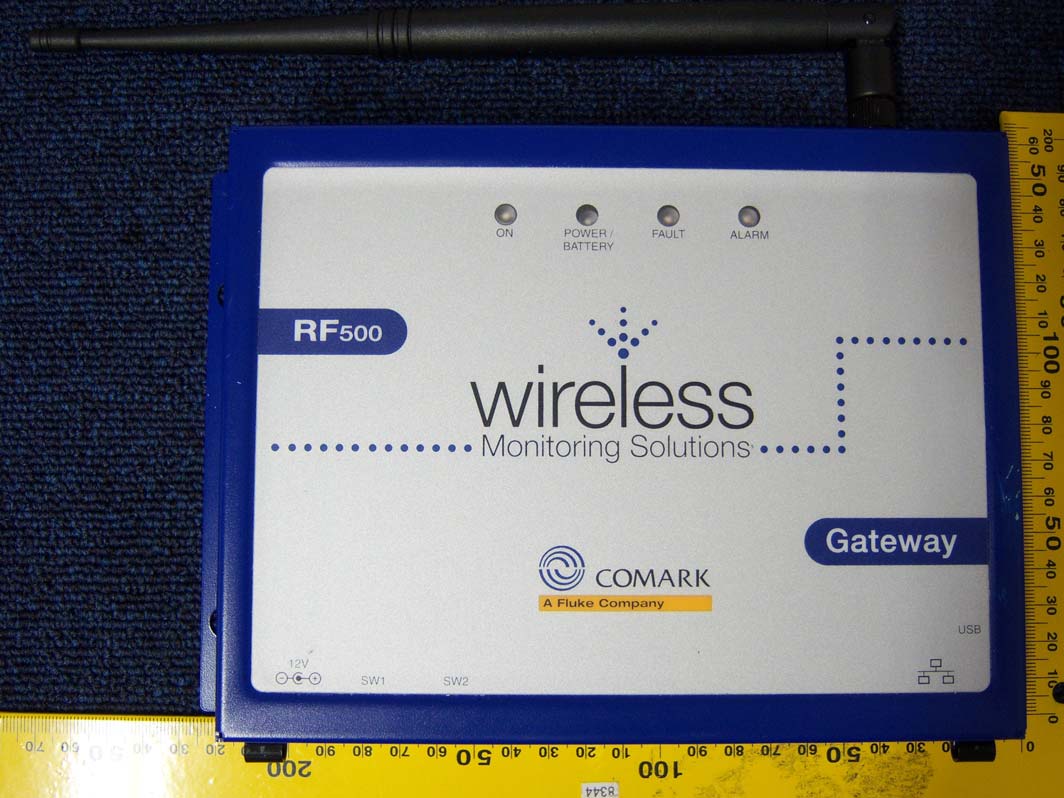
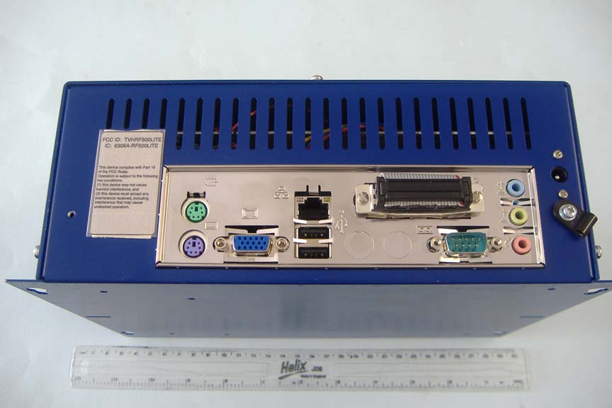
Top Overview RF Connector Overview PC Connection Overview
RF Module Track Side RF Component Side Contorl PCB RF Module Mounted Overview Contorl PCB RF Module Mounted Close Up PC Overview
RF500 General Description. Control Board: The RF module is mounted on the control PCB that provides the module with power and a coms interface the ITX small form factor motherboard COM port. The control board itself is designed host the output relay's and accurate real time clock (RTC). The RTC is backed up by a 3.6V Lithium Thionyl Chloride ½AA size cell. PC: The PC comprises of the ITX ML6000 motherboard running a 600MHz Eden processor and 256MB of 266MHZ RAM. It is supplied power via an off the shelf ITX power supply. Data is stored in a 40GB 2.5 inch hard disk. This is used to run the host application which interprets the data and provides the website front end. RF Board: SEE RF MODULE GENERAL DESCRIPTION.DOC GENERAL DESCRIPTION RF MODULE. This module enables RF communication to any device it is connected to using the EmberNet 802.15.4 compliant stack supplied by Ember Corporation. This is a 4- layer double-sided surface mount PCB. This module exhibits a nominal transmit power of –0.5dBm and a receive sensitivity of –94dBm. It uses the 2.4GHz radio frequency range and is designed to comply with the IEEE 802.15.4 standard for short range wireless communication. Microcontroller. The MPU used for this design is the Atmel ATmega128L, this runs the EmberNet self-organising mesh networking firmware in addition to the application firmware. Two external crystals are required for the application. First an 8MHz crystal is used with two loading capacitors to generate the microcontrollers system clock. This crystal is also used to generate the MAC time base to meet the requirements of 802.15.4 and hence is a high accuracy xtal with high stability loading capacitors. The second xtal is a standard 32.768KHz watch xtal which is used to drive the microcontroller in power-save mode. Capacitor C1, C2, C3 & C14 are used for power supply decoupling. EM2420 RF Transceiver. The EM2420 transceiver is configured for unbalanced operation, to accomplish that a balun circuit is used (components C20,C21,C22,C23,L1,L2 & L3) the values of which are critical. The balun circuit used in this design performs several functions. First, it performs the typical function of a balun, which is to convert the balanced (or differential) RF input/output to an unbalanced (or single-ended) port. Component pairs L2/C22 and L3/C20 accomplish this by shifting the phase of the two balanced signals RF_P and RF_N by ±90° (ideally). By shifting the phase of the signals 180° relative to each other, the signals combine in-phase (or separate out-of phase, depending on the signal direction). The second function performed by the balun is impedance matching. All component values were carefully chosen so that the impedance “looking into” the single-ended port of the balun is 50Ω. A well-matched balun circuit is essential to get full performance out of the EM2420. Finally, the balun is used to provide the appropriate DC bias to the internal PA and LNA when the device is transmitting and receiving, respectively. A DC path must exist from pin TXRX_SWITCH to pins RF_P and RF_N. In this design, this is accomplished with components L1 and L2. Component C22 is used for decoupling. Crystal. An external 16MHz xtal with two loading capacitors is required for the internal oscillator circuit. It is worth mentioning that, again, this is a high accuracy xtal used with specifically matched capacitors to ensure the transmit frequency’s accuracy. Any build defects e.g. additional solder, flux, incorrect component values, etc can all be causes of transmit frequency errors and result in a degradation of the modules performance. Bias resistor The bias resistor, R2, is used to set an accurate bias current for the internal current reference generator. A 43kΩ resistor with 1% tolerance must be used. Voltage regulator The on-chip voltage regulator is used to power all 1.8V power supply inputs. A 10μF tantalum capacitor (C15) is required to maintain stability of the regulator, and it must have an ESR between 0.5Ω and 5Ω. Since the ESR will vary with temperature, a series resistor may be used to prevent it from dropping below 0.5Ω. Power Supply Decoupling Proper power supply decoupling must be used for optimal performance. The placement and size of the decoupling capacitors are very important. To achieve the best performance, it is recommended that the component values, sizes, and placements used in this reference design are followed closely.
REPORT ON THE CERTIFICATION TESTING OF A COMARK Ltd RF500LITE WITH RESPECT TO THE FCC RULES CFR 47, PART 15.247 September 2007 INTENTIONAL RADIATOR SPECIFICATION TEST REPORT NO: RU1437/8458 COPY NO: 2 ISSUE NO: 1 FCC ID: TVHRF500LITE REPORT ON THE CERTIFICATION TESTING OF A COMARK Ltd RF500LITE WITH RESPECT TO THE FCC RULES CFR 47, PART 15.247 September 2007 INTENTIONAL RADIATOR SPECIFICATION TEST DATE: 3 rd – 5 th March 2008 TESTED BY: D WINSTANLEY APPROVED BY: J CHARTERS RADIO SECTION LEADER DATE: 1 st April 2008 Distribution: Copy Nos: 1. Comark Ltd 2. FCC EVALUATION LABORATORIES 3. TRL Compliance Ltd THIS DOCUMENT MAY BE REPRODUCED ONLY IN ITS ENTIRETY AND WITHOUT CHANGE RU1437/8458 Page 3 of 57 CONTENTS PAGE CERTIFICATE OF CONFORMITY & COMPLIANCE 4 APPLICANT’S SUMMARY 5 EQUIPMENT TEST CONDITIONS 5 TESTS REQUIRED 6 TEST RESULTS 7 -18 ANNEX PHOTOGRAPHS A PHOTOGRAPH No. 1: Test setup PHOTOGRAPH No. 2: Transmitter front view PHOTOGRAPH No. 3: Transmitter rear view PHOTOGRAPH No. 4: Transmitter PCB track side PHOTOGRAPH No. 5: Transmitter PCB component side APPLICANT’S SUBMISSION OF DOCUMENTATION LIST B TEST EQUIPMENT CALIBRATION C POWERLINE CONDUCTIONS GRAPH(s) D RADIATED SPURIOUS EMISSIONS E RADIATED BANDEDGE COMPLIANCE F 6dB BANDWIDTH G PEAK POWER CONDUCTED H POWER SPECTRAL DENSITY I CONDUCTED SPURIOUS EMISSIONS J MEASUREMENT UNCERTAINTY K Notes: 1. Component failure during test YES NO [ ] [X] 2. If Yes, details of failure: 3. The facilities used for the testing of the product contain in this report are FCC Listed. 4. The contents of the attached applicants declarations and other supplied information are not covered by the scope of this laboratory’s UKAS or FCC accreditations’ and is provided in good faith. RU1437/8458 CERTIFICATE OF CONFORMITY & COMPLIANCE CERTIFICATE OF CONFORMITY & COMPLIANCE FCC IDENTITY: TVHRF500LITE PURPOSE OF TEST: Certification TEST SPECIFICATION: FCC RULES CFR 47, Part 15.247 September 2007 TEST RESULT: Compliant to Specification EQUIPMENT UNDER TEST: RF500LITE EQUIPMENT SERIAL No: ENG01 ITU: EMISSION CODE: 1M6F1D EQUIPMENT TYPE: Temperature Monitor CARRIER EMISSION: 0.00611 W ANTENNA TYPE: Unique Antenna Connector GAIN ANTENNA: 7dBi Maximum Gain antenna FREQUENCY OF OPERATION: 2405MHz CHANNEL SPACING: N/A Wideband channel NUMBER OF CHANNELS: 1 FREQUENCY GENERATION: SAW Resonator [ ] Crystal [ ] Synthesiser [X] MODULATION METHOD: FHSS [ ] DSSS [X] Other [ ] POWER SOURCE(s): +110Vac TEST DATE(s): 3 rd – 5 th March 2008 ORDER No(s): SO6309 APPLICANT: Comark Ltd. ADDRESS: Comark House Gunnels Wood Park Gunnelswood Road Stevenage Heartforshire SG1 2TS United Kingdom TESTED BY: D WINSTANLEY APPROVED BY: J CHARTERS RADIO SECTION LEADER RU1437/8458 Page 5 of 57 APPLICANT’S SUMMARY EQUIPMENT UNDER TEST (EUT): RF500LITE EQUIPMENT TYPE: Temperature Monitor SERIAL NUMBER OF EUT: ENG01 PURPOSE OF TEST: Certification TEST SPECIFICATION(s): FCC RULES CFR 47, Part 15.247 September 2007 TEST RESULT: COMPLIANT Yes No [X] [ ] APPLICANT’S CATEGORY: MANUFACTURER IMPORTER DISTRIBUTOR TEST HOUSE AGENT [X] [ ] [ ] [ ] [ ] APPLICANT’S ORDER No(s): SO6309 APPLICANT’S CONTACT PERSON(s): Mr P Morrison E-mail address: [email protected] APPLICANT: Comark Ltd ADDRESS: Comark House Gunnels Wood Park Gunnelswood Road Stevenage Heartforshire SG1 2TS United Kingdom TEL: +44 1483 367367 FAX: +44 1483 367400 EUT(s) COUNTRY OF ORIGIN: United Kingdom TEST LABORATORY: TRL Compliance Ltd UKAS ACCREDITATION No: 0728 TEST DATE(s): 3 rd – 5 th March 2008 TEST REPORT No: RU1437/8458 RU1437/8458 Page 6 of 57 EQUIPMENT TEST / EXAMINATIONS REQUIRED 1. TEST/EXAMINATION RULE PART DETECTOR APPLICABILITY Intentional Emission Frequency: 15.247 Peak Yes Intentional Emission Field Strength: - - No Intentional Emission Band Occupancy: 15.247(a)1 Peak Yes Intentional Emission EIRP (mW): 15.247(b)1 Peak Yes Spurious Emissions – Conducted: 15.207 Quasi Peak Average Yes Spurious Emissions – Conducted: 15.247 Peak Yes Spurious Emissions – Radiated <1000MHz: 15.209 ,15.247 Quasi Peak Yes Spurious Emissions – Radiated >1000MHz: 15.247 15.209 Peak average Yes Transmitter Carrier Frequency Separation: 15.247(a)(1) Peak Yes Transmitter Maximum Peak Power Output Power: 15.247(b)(1) Peak Yes Transmitter Band Edge Conducted Emissions: 15.247(c) Peak Yes Transmitter Band Edge Radiated Emission: 15.247(c) Peak Yes Extrapolation Factor: 15.31(f) - Yes Maximum Frequency of Search: 15.33 - Yes Antenna Arrangements Integral: 15.203 - Yes Antenna Arrangements External Connector: 15.204 - Yes Restricted Bands: 15.205 - Yes 2. Product Description : 1M6F1D 3. Temperatures: Ambient (Tnom) 16 o C 4. Supply Voltages: Vnom +110Vac Note: Vnom voltages are as stated above unless otherwise shown on the test report page Single channel [X] 5. Equipment Category: Multi-channel [ ] Narrowband [ ] 6. Channel spacing: Wideband [X] RU1437/8458 Page 7 of 57 TRANSMITTER TESTS TRANSMITTER 6dB BANDWIDTH – CONDUCTED - PART 15.247(A)(2) Ambient temperature = 16 o C Relative humidity = 54% Conditions = Radio Lab Supply voltage = +110Vac Diagram Frequency Channel F lower F Higher Measured Bandwidth Limit 2.405MHz 1 2404.186795 MHz 2405.789359 MHz 1.602 MHz >500kHz Notes: 1 For analyser plots see annex G. Test Method: 1 The EUT was connected to the analyser via the unique antenna connector & a cable. 2 The 6dB bandwidth was recorded with the EUT activity transmitting data. TYPE OF EQUIPMENT MAKER/ SUPPLIER MODEL No SERIAL No TRL No ACTUAL EQUIPMENT USED SPECTRUM ANALYSER RHODE & SCHWARZ FSU46 200034 UH281 X EUT Analyser TRLUH281 Cable RU1437/8458 Page 8 of 57 TRANSMITTER TESTS TRANSMITTER - MAXIMUM PEAK POWER - CONDUCTED - PART 15.247(B)(3) Ambient temperature = 16 o C Relative humidity = 54% Conditions = Radio Lab Supply voltage = +110Vac Diagram Frequency MHz Channel Peak Power dBm Peak Power Watts Antenna Gain dBi Average Power Watts Limit Watts 2.405 1 0.86 0.00122 7 0.00611 1 Notes: 1 Gain of antenna 7dBi, maximum gain antenna supplied by manuf…
Text truncated - open the document above for the full version.
EUT on OATS. Close Up of EUT on OATS Powerline Conduction
| # | Rule Parts | Frequency Range | Power Output |
|---|---|---|---|
| 1 | 15C | 2.40 GHz - 2.41 GHz | 6.00 mW |

RF500A Gateway
Equipment Class
DTS - Digital Transmission System