TVMRC315TXRF Remote Controller
Lifestyle Entertainment Group, Inc.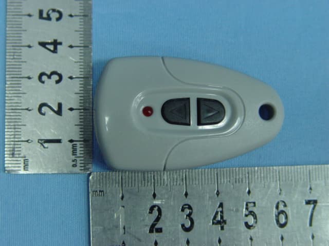
Click to zoom
Application Details
- Equipment Class
- DSC - Part 15 Security/Remote Control Transmitter
- Date of Grant
- Jan 16, 2006
- Application Purpose
- Original Equipment
- Date of Application
- Jan 16, 2006
- Equipment Note
- RF Remote Controller
- Frequency Range
- 315.00000000 - 315.00000000
- Country
- United States
Documents & Files
Document Text
Text extracted from the exhibit documents filed with the FCC. Open a document above to read the original.
Users Manual
LS2400-RC Manual Operating the Remote This wireless remote device controls the volume of the LiteSounds LS2400-XP wireless receiver. There are four sound level settings. Press the “Arrow Up” key to the adjust sound to the first level setting. The LED should turn on. Repeatedly press “Arrow Up” key to increase sound volume. Press the “Arrow Down” to reduce volume. Repeatedly press the “Arrow Down” key to decrease sound volume. Installing Batteries 1. Remove the battery compartment cover on the back of the remote control. 2. Check the battery polarity carefully and install the battery as shown. 3. Replace the battery compartment cover. NOTE* Use only NO. 27A replacement battery. 1.This device complies with Part 15 of the FCC Rules.Operation is subject to the following two conditions: (1) This device may not cause harmful interference, and (2) This device must accept any interference received, including interference that may cause undesired operation. 2.Changes or modifications not expressly approved by the party responsible for compliance could void the user’s authority to operate the equipment.
ID Label/Location Info
MODEL: LS2400-RC FCC ID: TVMRC315TX POWER: DC12V FREQUENCY: 315MHz MANUFACTURER: Lifestyle Entertainment Group, Inc. Made in China FCC MARKING/LABEL FOR PART15 17mm 17mm
Operational Description
Operation Description Model: LS2400-RC This is a remote controlled transmitter with address coder. IC1 SC2262 is a coder IC, it together with Q2, Q3, K1 and K2 form a switch modulation circuit. Q1, X1 (315MHz, SAW), C1 and C2 etc. form RF oscillating circuit. When either of K1 or K2 switched on, Q2 then works, IC1 outputs a pulse code signal to control Q3 switch on / off to ASK modulate the RF oscillating circuit. The transmitter produce non-periodic signal; The transmitter “ON/OFF” by manual, the released time less 5 seconds.
Schematics
1234 A B C D 4321 D C B A Title NumberRevisionSize A4 Date:16-Dec-2005Sheet of File:D:\CS2400\CS2400-XP.ddbDrawn By: Q2 9015 Q3 9014 Q1 3355 R3 104 R7 104 R8 103 R1 103 1 1 2 2 K2 K1 1 7 2 6 3 8 4 GND 9 5 VCC 18 17 16 15 14 13 12 11 10 IC1 SC2262 D1 LED 1 2 3 X1 315MHz R2 473 L4 PCB4 L3 PCB3L2 PCB2 L1 PCB1 C1 2P C2 4P R4 223 R5 125 VCC P C B A N T E N N A K3 BT 12V R6 103 RF REMOTE CONTROLLER:LS2400-RC SCHEMATIC DIAGRAM LS2400-RC SCHEMATIC UPDATE:2005,11,17 01 JB.XU This document was created with Win2PDF available at http://www.daneprairie.com. The unregistered version of Win2PDF is for evaluation or non-commercial use only.
Test Report
Page 1 of 22 FCC ID: TVMRC315TX ACCURATE TECHNOLOGY CO. LTD REPORT NO. ATE20052288 FCC CERTIFICATION On Behalf of Lifestyle Entertainment Group, Inc. RF Remote Controller Model No.: LS2400-RC FCC ID: TVMRC315TX Prepared for : Lifestyle Entertainment Group, Inc. Address : 2918 Cantos De Los Ciervos San Clemente, California 92673 USA Prepared by : ACCURATE TECHNOLOGY CO. LTD Address : F1, Bldg. A, Changyuan New Material Port, Keyuan Rd. Science & Industry Park, Nanshan, Shenzhen, Guangdong P.R. China Tel: (0755) 26503290 Fax: (0755) 26503396 Report Number : ATE20052288 Date of Test : December 20, 2005 Date of Report : December 23, 2005 Page 2 of 22 FCC ID: TVMRC315TX ACCURATE TECHNOLOGY CO. LTD REPORT NO. ATE20052288 TABLE OF CONTENTS Description Page Test Report Certification 1. GENERAL INFORMATION .......................................................................................................... 4 1.1. Description of Device (EUT)....................................................................................................................4 1.2. Description of Test Facility ......................................................................................................................4 1.3. Measurement Uncertainty.........................................................................................................................4 2. MEASURING DEVICE AND TEST EQUIPMENT ..................................................................... 5 3. THE FIELD STRENGTH OF RADIATION EMISSION ............................................................ 6 3.1. Block Diagram of Test Setup....................................................................................................................6 3.2. The Field Strength of Radiation Emission Measurement Limits..............................................................6 3.3. Configuration of EUT on Measurement ...................................................................................................7 3.4. Operating Condition of EUT ....................................................................................................................7 3.5. Test Procedure ..........................................................................................................................................7 3.6. The Field Strength of Radiation Emission Measurement Results ............................................................8 4. OCCUPIED BANDWIDTH ........................................................................................................... 10 4.1. Block Diagram of Test Setup..................................................................................................................10 4.2. The Bandwidth of Emission Limit According To Section 15.231(c) .....................................................10 4.3. EUT Configuration on Measurement .....................................................................................................11 4.4. Operating Condition of EUT ..................................................................................................................11 4.5. Test Procedure ........................................................................................................................................11 4.6. Measurement Result ...............................................................................................................................12 5. RELEASE TIME MEASUREMENT............................................................................................ 13 5.1. Block Diagram of Test Setup..................................................................................................................13 5.2. Release Time Measurement According To Section 15.231(a) ...............................................................13 5.3. EUT Configuration on Measurement .....................................................................................................14 5.4. Operating Condition of EUT ..................................................................................................................14 5.5. Test Procedure ........................................................................................................................................14 5.6. Measurement Result ...............................................................................................................................15 APPENDIX I ( TEST CURVES) (6pages) Page 3 of 22 FCC ID: TVMRC315TX ACCURATE TECHNOLOGY CO. LTD REPORT NO. ATE20052288 Test Report Certification Applicant : Lifestyle Entertainment Group, Inc. Manufacturer : Dongguan City Chanping Taixing Hardware Craft Co., Ltd. EUT Description : RF Remote Controller (A) MODEL NO.: LS2400-RC (B) SERIAL NO.: N/A (C) POWER SUPPLY: 12V DC (“27A” battery Type) Measurement Procedure Used: FCC Rules and Regulations Part 15 Subpart C Section 15.231: 2004 & ANSI C63.4: 2003 The device described above is tested by ACCURATE TECHNOLOGY CO. LTD to determine the maximum emission levels emanating from the device. The maximum emission levels are compared to the FCC Part 15 Subpart C Section 15.231 limits. The measurement results are contained in this test report and ACCURATE TECHNOLOGY CO. LTD is assumed full responsibility for the accuracy and completeness of these measurements. Also, this report shows that the Equipment Under Test (EUT) is to be technically compliant with the FCC requirements. This report applies to above tested sample only. This report shall not be reproduced in part without written approval of ACCURATE TECHNOLOGY CO. LTD. Date of Test : December 20, 2005 Prepared by : (Engineer) Reviewer : (Quality Manager) Approved & Authorized Signer : (Manager) Page 4 of 22 FCC ID: TVMRC315TX ACCURATE TECHNOLOGY CO. LTD REPORT NO. ATE20052288 1. GENERAL INFORMATION 1.1. Description of Device (EUT) EUT : RF Remote Controller Model Number : LS2400-RC Power Supply : 12V DC (“27A” battery Ty…
Text truncated - open the document above for the full version.
Contact Information
Applicant
Leon Sievers(Director)
Test Firm
Accurate Technology Co., Ltd.Sean Liu
Technical Specifications
| # | Rule Parts | Frequency Range | Power Output |
|---|---|---|---|
| 1 | 15.231 | 315 MHz - 315 MHz | - |
Other Applications from Lifestyle Entertainment Group, Inc.
TVMFM69TX
Jan 16, 2006FM Transmitter
Equipment Class
DXX - Part 15 Low Power Communication Device Transmitter