Text extracted from the exhibit documents filed with the FCC. Open a document above to read the original.
Instruction Manual WL-286 / WL-286T USING INSTRUCTION GETTING STARTED 1. Open the battery compartment of the transmitter cover. 2. Insert 3 X AAA batteries into transmitter battery compartment. Make sure the plus and minus poles of battery were correctly touched their contacts. *(When use with USB cable for power supply. Connect USB cable to Power Jack & USB port on PC) *(When use with AC/DC adaptor for power supply. Connect DC plug to Power Jack & AC plug to wall outlet) 3. Close the battery compartment cover with a click. 4. Plug the transmitter into audio sources and press the power button to ON, the LED indicator of USB transmitter should light up. 5. Open the battery compartment of the left hand side headphones cover . 6. Insert 2 X AAA batteries into headphones battery compartment. Make sure the plus and minus poles of battery were correctly touched their contacts. 7. Power on the wireless headphone. 8. Check the power LED rightly light up. 9. Press the channel selector of transmitter to find a best channel [8 channel selectable], which you can clearly listen to the music through the headphone speaker . TROUBLE SHOOTING No audio at headphones 1. Make sure the battery rightly inserted into the battery compartment. 2. Check the battery voltage or replace new batteries. 3. Check the headphone volume control not at minimum level. 4. Set up the channel of transmitter and headphone at the same one, the channel might be different from other 2.4GHz electronic products Audio is distorted or noisy 1. Check the battery voltage or replace new batteries. 2. If the audio level at audio source (TV / Discman / MP3 etc.) is too high, turn down audio source volume. 3. Set up the channel of transmitter and headphone at the same one, the channel might be different from other 2.4GHz electronic products. 4. Check the audio sources input to make sure is not distorted or noisy . 5. Turn off other 2.4GHz electrical appliances, such as microwave oven, 2.4GHz cordless phone, WLAN or Bluetooth headset, which may cause RF interference. Headphones Transmitter Battery Cover LED Power Indicator Power Switch LED Power Indicator Power Switch Channel Selector Switch Power Jack Battery Cover WL-286/WL-286T 說明書4-04-126-01,規格: 105x165mm K WL-286/WL-286T 說明書4-04-126-01,規格: 105x165mm K 2.4GHz DigitalWireless Headphones Audio drops out intermittently or crackles 1. Check the battery voltage or replace new batteries. 2. Set up the channel of transmitter and headphone at the same one. 3. If audio signal is too weak, move listener ’s position close to transmitter. 4. Turn off other 2.4GHz electronic products, such as microwave oven 2.4GHz cordless phone, WLAN or Bluetooth headset, which may cause RF Interference. GENERAL SAFETY SUMMARY CAUTION RISK OF ELECTRONIC CHOCK DO NOT OPEN CAUTION: DO NOT REMOVE THE COVER FOR REDUCING THE RISK OF ELECTRIC SHOCK. NO USER-SERVICEABLE PARTS INSIDE REFER SERVICING T O QUALIFIED SERVICE PERSONNEL. WARNING To prevent fire or shock hazard, do not expose the unit to rain or moisture. IMPORTANT SAFETY INSTRUCTIONS 1. All the safety and operating instructions should be read before the product is operated. 2. The safety and operating instructions should be retained for future reference. 3. All warnings on the product and in the operating Instructions should be adhered to. 4. All operating and use instructions should be followed. 5. Do not use liquid cleaners or aerosol cleaners. Use a damp cloth for the cleaning. 6. Do not use attachments not recommended by the products manufacturer if they may cause hazards. 7. Do not use this product near water - for example, near a bath tub, wash bowl, kitchen sink, or laundry tub, in a wet basement or near a swimming pool, and the like. 8. Never push objects of any kind into this product through openings as they may touch dangerous voltage points or short-out parts that could result in a fire or electronic shock. Never spill liquid of any kind on the product. SPECIFICATION General: Frequency Range: 2400 – 2483.5MHz Supply Voltage TX: 4.5V (AAA x 3) / 5 VDC INPUT RX: 2.4V (AAA x 2) Modulation: FSK Channel Number: 8 Channel Spacing: 9MHz Channel Frequency: 2410, 2419 – 2473MHz Frequency Stability: + 100KHz Dynamic Range: 90dB (Typ.) Separation: 80dB (Typ.) S/N Ratio : 90dB (Typ.) THD: -75dB (Typ.) Headphones: Driver Unit: 30mm Cobalt Magnet Frequency Response: 20Hz – 20KHz Impedance: 32 Ohm + 10% Maximum Power Handling: 100 mW “NOTE: THE MANUFACTURER IS NOT RESPONSIBLE FOR ANY RADIO OR TV INTERFERENCE CAUSED BY UNAUTHORIZED MODIFICATIONS TO THIS EQUIPMENT. SUCH MODIFICATIONS COULD VOID THE USER’S AUTHORITY TO OPERATE THE EQUIPMENT.” *This device complies with part 15 of the FCC Rules.Operation is subject to the following two conditions: (1) This device may not cause harmful interference,and (2) this device must accept any interference received, including interference that may cause undesired operation. *Changes or modifications not expressiy approved by the party responsible for compliance could void the user’s authority to operate the equipment*
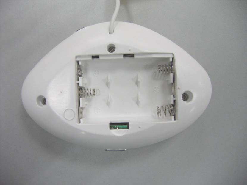
1.&2. . The revised user manual downloaded to web site 3. The internal photos must show radio with the shielding removed. Please revise internal photos. The revised internal photos downloaded to website. 4. The WDA Module documents was download to web site.
Data Sheet CUSTOMER PRODUCT 2.4GHz Wireless Digital Audio Module MODEL NO. DIO-T008L/U DATE Aug. 2005 義聯科技股份有限公司 ELANsat Technologies Inc. 5F, No.12, Innovation Road I, Science-Based Industrial Park, Hsin-chu, Taiwan, R.O.C. TEL:+886-3-563-5105 FAX:+886-3-563-5107 http://www.elansat.com E-mail:[email protected] DOC NO: PRE-1.0 Data Sheet Model: DIO-T008L/U ELANSAT Technologies Inc. Version: 1.1 Sep. 2005 Page 2 of 9 1. FEATURES.......................................................................................................................................3 2. APPLICATIONS.................................................................................................................................3 3. SPECIFICATION................................................................................................................................4 4. P IN CONFIGURATION AND MECHANICAL INFORMATION...............................................................5 5. PIN DESCRIPTION............................................................................................................................6 6. Channel Mode Setting Table.........................................................................................6 7. Application Circuits.....................................................................................................7 8. Operation of DIO-T008................................................................................................8 9. Application information................................................................................................9 TABLE OF CONTENTS Data Sheet Model: DIO-T008L/U ELANSAT Technologies Inc. Version: 1.1 Sep. 2005 Page 3 of 9 Features 1. SNR: 90dB 2. THD: < 0.1% 3. Frequency Response: -1dB @20 Hz ~ 20 kHz 4. Linear PCM format: 44.1K sampling rate and 16-bits representation. 5. Non-compression to perform high audio quality with only 0.5ms delay time. 6. POP noise prevention during power-on period. 7. 4-bits ID function. 8. One transmitter and multi-receivers application. 9. FSK design to ensure Low power consumption for portable application. 10. Embedded antenna for cost-effect and quick development. 11. Operating at 2.4GHz ISM band with 8 selectable channels. 12. Application distance up to 30 meter (L.O.S.) with perfect reception. 13. USB interface compliant to: Win98 SE/ WinME/ Win2000/ WinXP and MacOS 9.2.1/MacOS10.2 USB specification v1.1 USB audio device class specification v1.0 USB HID class specification v1.1 Applications Wireless headphone Wireless speakers Home theater rear speakers MP3, CD player and DVD player USB and PC applications 2.4GHz Wireless Digital AudioWireless Digital Audio Specification Data Sheet Model: DIO-T008L/U ELANSAT Technologies Inc. Version: 1.1 Sep. 2005 Page 4 of 9 Specification Model Name DIO-T008L DIO-T008U Description Line-in USB Interface Application Speaker PC Audio Power supply Supply Voltage 3.3 ± 0.1 VDC USB Power supply Current Consumption 68 mA @ 3.3 VDC (Typical) 68 mA @5 VDC (Typical) Audio Section ( tested with 1KHz tone) Frequency Response 20 ~ 20 KHz, -1dB 20 ~ 20 KHz, -1dB Dynamic range 90 dB (Typical) 83 dB (Typical) Separation 80 dB (Typical) 80 dB (Typical) SNR 90 dB (Typical) 90 dB (Typical) THD -75dB (Typical) -75dB (Typical) Input level 2 Vpp (Max) - Input impedance >10 KOhm - RF Section Frequency Range 2400 ~ 2483.5 MHz 2400 ~ 2483.5 MHz Demodulation FSK FSK Channel Number 8 8 Channel Spacing 9 MHz 9 MHz Channel Frequency 2410, 2419 ~ 2473 MHz 2410, 2419~ 2473 MHz Frequency Stability ±100 KHz ±100 KHz TX Power 8 ~ 10 dBm (Typical) 8 ~ 10dBm (Typical) Operation Operating Temperature -10 ~ +60 (degrees Celsius) -10 ~ +60 (degrees Celsius) Wireless Digital Audio Specification Data Sheet Model: DIO-T008L/U ELANSAT Technologies Inc. Version: 1.1 Sep. 2005 Page 5 of 9 Pin Configuration and Mechanical Information Wireless Digital Audio SpecificationWireless Digital Audio SpecificationWireless Digital Audio Specification Data Sheet Model: DIO-T008L/U ELANSAT Technologies Inc. Version: 1.1 Sep. 2005 Page 6 of 9 Pin Description (for DIO-T008L) No. Symbol Function 3 USER_BIT The data stream input, which will be transmitted to USER_BIT of RX Module. (Maximum data rate is 5Kbps) 4 FORMAT Pull up for scrambling with “01” pattern. Pull down for scrambling with random pattern. (internal pull high) 5 OB Pull down to enable out-band channel for testing purpose. (internal pull high) 6 TACT_SW Impulse low to scan channel for TACT mode. (internal pull high) (see table for channel mode setting) 7 VCC 3.3 VDC input for DIO-T008L. 8 ADC_L L channel of audio input to ADC directly. A DC blocking capacitor (>1uF) should be added. 9 GND Grounding 10 ADC_R R channel of audio out from DAC directly. A DC blocking capacitor (>1uF) should be added. 11 SW2 12 SW1 13 SW0 Pull low for DIP mode channel selection (internal pull high) 14 ID3 15 ID2 16 ID1 17 ID0 Pull low for ID selection (internal pull high) 18 CH_MODE See “channel mode setting table” for detail Pull high for TACT mode and low for DIP mode. (internal pull high) Channel Mode Setting Table (for DIO-T008L) Channel Mode CH_MODE (Pin 18) Function DIP GND Set SW0, SW1 and SW2 to change channel. TACT X Switch channel by channel when each impulse-low is applied to TACT_SW (Pin 6) * “X” means floating. Wireless Digital Audio SpecificationWireless Digital Audio Specification Data Sheet Model: DIO-T008L/U ELANSAT Technologies Inc. Version: 1.1 Sep. 2005 Page 7 of 9 Application Circuits (for DIO-T008L) PCB layout guideline Any metal (including PCB track and holding screw) around the antenna will result in changing impedance and radiation pattern of the antenna. These two parameters are the most important for antenna performance. Keep in mind that reserve as much as space around the antenna if possible. Connect all parts as close as possible to the pins of module and reduce the length of routing traces, to help on good audio performance, proper…
Text truncated - open the document above for the full version.
5 5 4 4 3 3 2 2 1 1 DD CC BB AA Cobalt Industrial Co. Ltd. Project No.:WL-286 2.4G Wireless Module + Headphone (Transmitter) Title 1.0 2.4G Wireless Transmitter A 12Wednesday, November 30, 2005 Cobalt Industrial Co. Ltd Title SizeDocument NumberRev Date:Sheet of 5 5 4 4 3 3 2 2 1 1 DD CC BB AA Power 1.0 2.4G Wireless Transmitter A 22Wednesday, November 30, 2005 Cobalt Industrial Co. Ltd Title SizeDocument NumberRev Date:Sheetof VCC U2 2.4G Wireless Module DIO-T008L 3 4 5 6 7 8 9 1011 12 13 14 15 17 18 15 USER_BIT FORMAT OB TACT_SW VCC DAC_L GND DAC_RSW2 SW1 SW0 ID3 ID2 ID0 CH_MODE ID1 L1 36uH D1 / LED Blue Colour C8 103 1 2 C3 100uF/25V C9 2.2uF/50V C2 104 1 2 C5 100uF/25V U1 LM78L05 1 2 3 Vin G N D Vout C1 103 1 2 C6 220uF/16V S2 Channel Selection J1 DC JACK 1 2 3 L2 15uH C10 2.2uF/50V L R G Audio Plug 1 2 3 BT1 BATTERY (AAAx 3 / 4.5V) C4 103 1 2 S1 Power Switch 14 25 36 R1 1K C7 100uF/25V
Report No.: GLEMO051203069RF(I) Page: 1 of 30 FCC ID: TWF-WL-286 Authorized Signature: Jerry Chen Manager Thi s r epor t r efer s to the Gener al C ondi ti ons for Inspecti on and Testi ng Ser vi ces, pr i nted over l eaf Thi s r epor t detai l s the r esul ts of the testi ng car r i ed out on one sampl e. The r esul ts contai ned i n thi s test r epor t do not r elate to other sampl es of the same pr oduct. The manufactur er shoul d ensur e that al l pr oducts i n ser i es pr oducti on ar e i n confor mi ty wi th the pr oduct sample detailed in this r epor t. Thi s r epor t may onl y be r epr oduced and di str i buted i n ful l . If the pr oduct i n thi s r epor t i s used i n any confi g ur ati on other than that detai l ed i n the r epor t, the manufactur er must ensur e the new system compl i es wi th al l r el evant standar ds. Any menti on of SGS Inter nati onal El ectr i cal Appr oval s or testi ng done by SGS Inter nati onal El ectr i cal Appr oval s i n connecti on wi th, di str i buti on or use of the pr oduct descr i bed i n thi s r epor t must be appr oved by SGS Inter nati onal El ectr i cal Appr oval s i n wr i ti ng . M ember of the SGS Gr oup ( Soci été Génér al e de Sur vei l l ance) SGS-CSTC Standards Te chnical Se rv ice s Ltd N o.198 Kezhu R oad, Sci ence Town Economi c& Technol og y D evel opment D i str i ct Guang zhou, C hi na 510663 Tel ephone: + 86 ( 0) 20 82155555 Fax: + 86 ( 0) 20 82075059 Emai l : sg s_i nter net_oper ati ons@sg s.com FEDERAL COMMUNICATIONS COMMISSION TEST REPORT Application No. : GLEMO051203069RF Applicant: Cobalt Industrial Co.,Ltd. FCC ID: TWF-WL-286 Fundamental Carrier Frequency : 2.40992GHz , 2.41902GHz , 2.42802GHz , 2.43702GHz 2.44602GHz , 2.45502GHz , 2.46402GHz, 2.47292GHz Equipment Under Test (EUT): Name: 2.4GHz Wireless Digital Headphone (Transmitter part) Item No.: WL Series♣ ♣ Please refer to section 2 of this report which indicates which item was actually tested and which were electrically identical. Standards: FCC PART 15: 2005 Date of Receipt: 6 December 2005 Date of Test: 7 to 16 December 2005 Date of Issue: 16 December 2005 Test Result : PASS * * In the configuration tested, the EUT complied with the standards specified above. SGS-CSTC Standards Te chnical Se rv ice s Ltd. Report No.: GLEMO051203069RFF(I) Page: 2 of 30 FCC ID: TWF-WL-286 2 Test Summary Test Test Requirem ent Stanadard Paragraph Result Conducted Emission (150KHz to 30MHz) FCC PART 15 :2005Section 15. 207 PASS Flied Strength of Fundamental FCC PART 15 :2005Section 15.249 (a) PASS Flied Strength of Harmornics or other Frequency FCC PART 15 :2005 Section 15.249 (a) Section 15.209 PASS Occupied Bandwidth FCC PART 15 :2005Section 15.249 PASS Band Edges Measurement FCC PART 15 :2005Section 15.249 (d) PASS Item No.: WL Se ri e s Only the Item WL-286 was tested, since the electrical circuit design, layout, components used and internal wiring were identical for the above items, with only difference being the item no.’s and outer decoration. SGS-CSTC Standards Te chnical Se rv ice s Ltd. Report No.: GLEMO051203069RFF(I) Page: 3 of 30 FCC ID: TWF-WL-286 3 Contents Page 1 COVER PAGE ............................................................................................................................... 1 2 TEST SUMMARY ............................................................................................................................ 2 3 CONTENTS ..................................................................................................................................... 3 4 GENERAL INFORMATION .............................................................................................................. 4 4.1 CLIEN T INFORMATION...................................................................................................................... 4 4.2 GENERAL DESCRIPTION OF E.U.T. .................................................................................................... 4 4.3 DESCRIPTION OF SUPPORT UNITS..................................................................................................... 4 4.4 STANDARDS APPLICABLE FOR TESTING.............................................................................................. 4 4.5 TEST LOCATION............................................................................................................................. 4 4.6 OTHER INFORMATION REQUESTED BY THE CUSTOMER.......................................................................... 4 4.7 TEST FACILITY...............................................................................................................................5 5 TEST RESULTS............................................................................................................................... 6 5.1 TEST INSTRUMENTS....................................................................................................................... 6 6 TEST PROCEDURE & M EASUREM ENT DATA................................................................................ 7 6.1 CONDUCTED EM ISSIONS MAINS TERM INALS, 150KHZ TO 30MHZ.......................................................... 7 6.1.1 E.U.T. Operation................................................................................................................. 7 6.1.2 Measurement Data .............................................................................................................. 7 6.2 RADIATED EMISSIONS.................................................................................................................... 10 6.2.1 Test in transmitting mode .................................................................................................. 10 6.2.2 Occupied Bandwidth & Band Edge............................................................................. 14-30 SGS-CSTC Standards Te chnical Se rv ice s Ltd. Report No.: GLEMO051203069RFF(I) Page: 4 of 30 FCC ID: TWF-WL-286 4 General Informa…
Text truncated - open the document above for the full version.
198 Kezhu Rd, Scientech Pk Guangzhou · Guangzhou · China
| # | Rule Parts | Frequency Range | Power Output |
|---|---|---|---|
| 1 | 15C | 2.41 GHz - 2.47 GHz | - |

BLUETOOTH STEREO HEADSET
Equipment Class
DSS - Part 15 Spread Spectrum Transmitter