TXL30072WIRELESS DRIVEWAY MONITOR
Safety Technology International, Inc.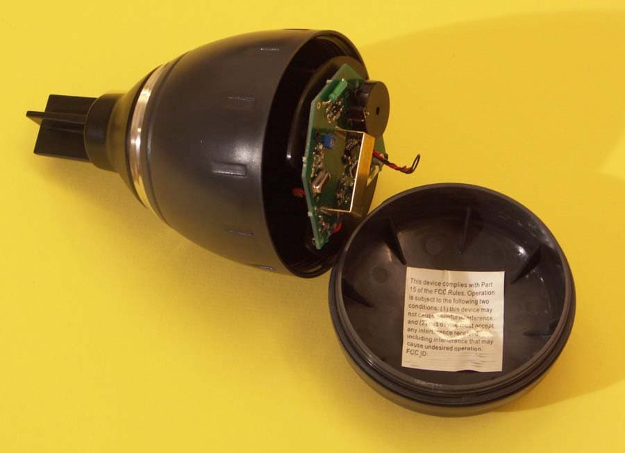
Click to zoom
Application Details
- Equipment Class
- DSC - Part 15 Security/Remote Control Transmitter
- Date of Grant
- Feb 01, 2006
- Application Purpose
- Original Equipment
- Date of Application
- Feb 01, 2006
- Equipment Note
- WIRELESS DRIVEWAY MONITOR
- Frequency Range
- 314.50000000 - 314.50000000
- Country
- United States
Documents & Files
Document Text
Text extracted from the exhibit documents filed with the FCC. Open a document above to read the original.
Users Manual
Page 1 Driveway Monitor 30078 Installation Instructions Wireless Driveway Monitor TM Model # 30078 v5-3 Installing Batteries in the Driveway Sensor: 1. Open the case of the driveway sensor by unscrewing the top in a counterclockwise direction. 2. Remove the battery holder from inside the sensor case by lifting up. Insert two "C" alkaline batteries (not included). Note the positive and negative battery orientation. The sensor will make a faint cricket sound when activated. 3. If needed, lubricate the o-ring with a thin coating of Vaseline. (Recommended every time the batteries are changed.) 4. Close the case back together tightly. The O-ring should provide a water resistant seal. Setting Up the Driveway Monitor Receiver: Plug the antenna into the red RCA jack on the back of the receiver (the top jack). The an- tenna should be vertical. Plug the AC adapter into the power jack on the back of the receiver (the bottom jack). The receiver will beep and the alert light will turn on red for 5 seconds - then come on green. Testing the System Prior to Installation The sensor and receiver are factory set to a unique code. Before installing the sensor outside, test the unit by rotating the driveway sensor (rotate the sensor more than 5 feet away from the receiver). (If you listen carefully, you will hear the sensor softly chirp like a cricket when the unit is transmitting a signal.) The receiver will chime 2 times and the ALERT light will flash RED for 15 minutes. If the receiver does not chime or the red ALERT light does not come on during this test - refer to the Trouble Shooting section of the Reference Guide. Mounting the Driveway Sensor: 1.The stake comes in three parts. Assemble the parts by pressing the cap onto the tube and pressing the tube onto the stake. The cap protects the top of the tube during hammering. 2. Pound the assembled stake into the ground on the side of the driveway using a regular hammer. Never hammer the stake with the sensor attached. 3. Once the stake and tube are firmly in the ground, remove the cap and mount the sensor onto the tube. Another option is to mount the sensor to a fence, tree, or post using the included wall bracket. The higher the sensor is mounted off the ground, the better the trans- mitting distance is to the home. The object to which you mount the driveway sensor must not move in the wind to avoid false triggers on windy days. Do not mount the sensor to iron or steel objects. Whenever a vehicle drives by, you will be notified in the house. If you have any problems with: • Getting the system to function, • Getting the system to work from the end of your driveway, • Using 2 or more sensors or receivers with your system, • Buying additional accessories, then Please refer to the separate TROUBLESHOOTING GUIDE. Driveway Monitor 30078 Page 2 2306 Airport Rd • Waterford, Michigan 48327 USA www.STI-USA.com ©2006 Safety Technology International, Inc This device complies with Part 15 of the FCC Rules. Operation is subject to the following two conditions: (1) this device may not cause harmful interference, and (2) this device must accept any interference received, including interference that may cause undesired operation. FCC ID: User is cautioned that changes or modifications not expressly approved by Safety Technology International could void the user's authority to operate this equipment. Covered under US Patent Numbers: 4,851,775 & 5,239,264 Safety Technology International, Inc
Block Diagram
Created by Mark Gottlieb Page 2 of 10 01/23/06 6:58 PM 5. List of Semiconductor Designations and Functions: Qty Ref Part Function 1 Q1 MMBR951 RF Small Signal NPN Transistor 2 Q2, Q3 2N3904 General Purpose NPN Transistor 1 U1 PIC12LC508A 8-pin, 8-bit CMOS Microcontroller 6. Schematic Diagram – see attachment 7. Block Diagram Frequency determined by SAW resonator in feedback. SAW Transistor Amplifier Gating Microcontroller Radiating Tank Magnetometer FCC Application for 30072 Driveway Monitor TX v3.5 Safety Technology International, Inc
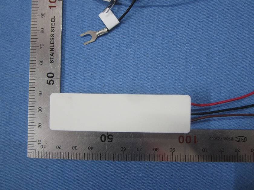
External Photos
SAFETY TECHNOLOGY INTERNATIONAL, INC. FCC ID: TXL30072 EXTERNAL PHOTOS
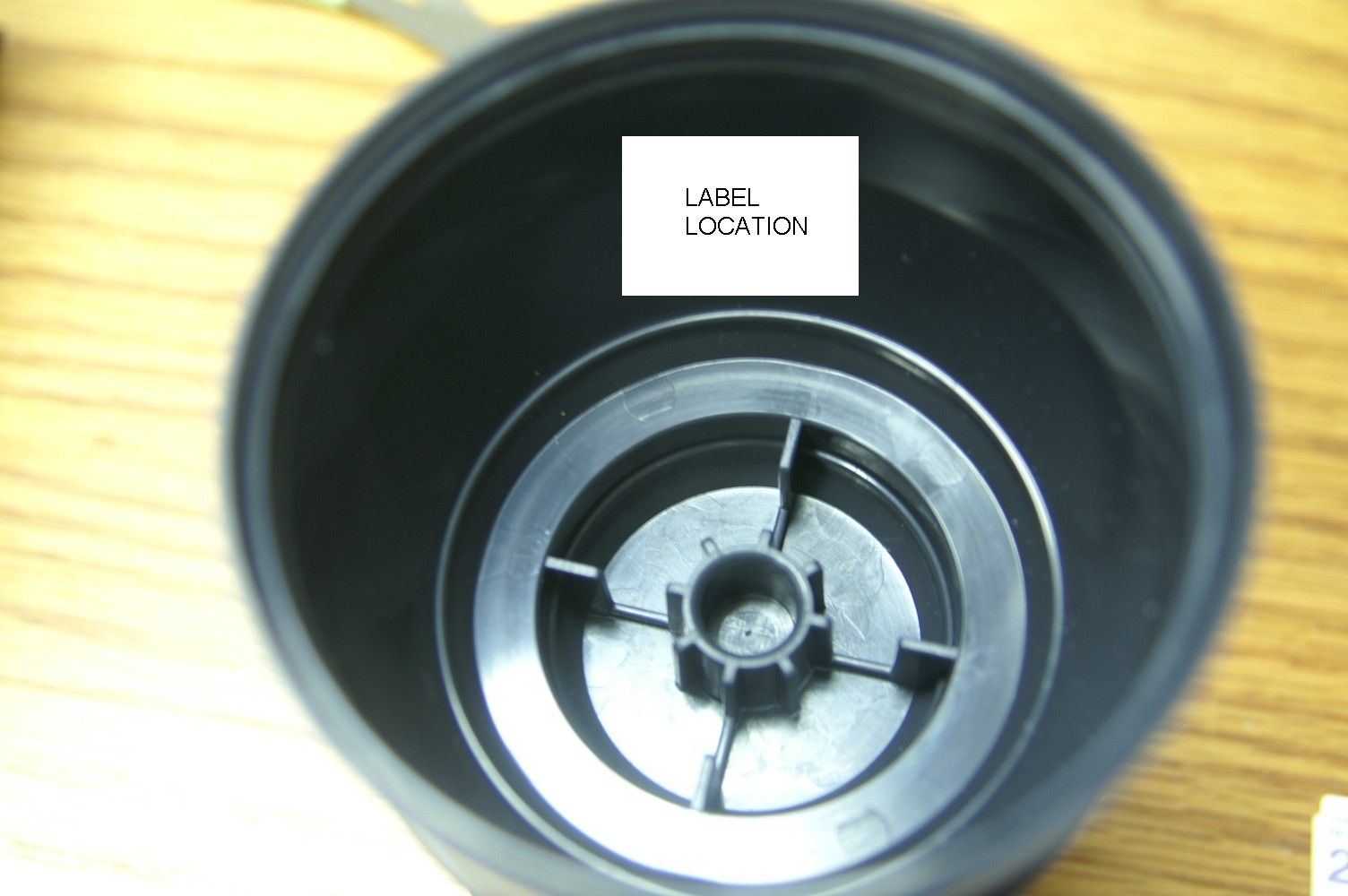
ID Label/Location Info
Created by Mark Gottlieb Page 5 of 10 01/23/06 6:58 PM 14. FCC Label Artwork: Location – Label on inside of case. Driveway Monitor This device complies with part 15 of the FCC Rules. Operation is subject to the following two conditions: (1) this device may not cause harmful interference, and (2) this device must accept any interference received, including interference that may cause undesired operation. FCC ID: TXL30072 Safety Technology International, Inc. Waterford, MI USA www.STI-USA.com Part #30072 Shrink to fit 0.70” by 1.40” label. FCC Application for 30072 Driveway Monitor TX v3.5 Safety Technology International, Inc
Internal Photos
Created by Mark Gottlieb Page 6 of 10 01/23/06 6:58 PM 15. Photographs: FCC Application for 30072 Driveway Monitor TX v3.5 Safety Technology International, Inc Created by Mark Gottlieb Page 7 of 10 01/23/06 6:58 PM FCC Application for 30072 Driveway Monitor TX v3.5 Safety Technology International, Inc Created by Mark Gottlieb Page 8 of 10 01/23/06 6:58 PM FCC Application for 30072 Driveway Monitor TX v3.5 Safety Technology International, Inc Created by Mark Gottlieb Page 9 of 10 01/23/06 6:58 PM FCC Application for 30072 Driveway Monitor TX v3.5 Safety Technology International, Inc
Operational Description
Created by Mark Gottlieb Page 3 of 10 01/23/06 6:58 PM 8. Circuit Description A microcontroller operates in a cyclic powerup/powerdown mode. About once per second it wakes up, operates a magnetometer to determine the ambient field, and goes back to sleep. If the ambient field changes, for instance because a car drives by close to the sensor, the microcontroller sends a signal. A 24-bit on-off keyed PPM message is sent at intervals of about 110 milliseconds. The total “keyed-on” time of the message is less than 10 milliseconds, so the duty factor is less than 10 percent. The transmitter is a 314.5 MHz radiating Pierce oscillator, whose frequency is stabilized by the presence of a surface-acoustic-wave (SAW) resonator in the feedback loop. The transmitter is keyed by applying forward bias to the emitter-base junction. 9. Owner’s/Operator’s Instruction Book: The Instruction Manual is available in a separate file (pdf format) attached to this document. 10. Transmitter Tune-Up (Alignment) Procedure: Attach an antenna to a HAMEG HM5006 spectrum analyzer. Any kind of antenna will do, for example a coaxial cable ending in two wires 0.25 meter long, one connected to the shield of the coax cable and the other to the center conductor, and pulled in opposite directions. Set the controls as follows: Marker "on" set to the center of the screen. Center frequency adjustment set to 314.50 MHz. Bandwidth button OUT (250 KHz) Video filter OFF (out). Scan width 0.1 MHz/DIV Two attenuator buttons IN and three OUT. Recheck the center frequency display after every ten units tuned. Adjust a regulated bench power supply to 3.1 volt. Short circuit the output of the power supply and adjust the current to 50 mA. Use clip leads to connect the power supply to the battery terminals of the circuit board. Using tweezers, short together the two terminals labeled "tune". (You may leave the tweezers in the terminal holes or remove them - whichever is convenient.) Turn the tuning adjustment to maximize the reading on the meter. There should be two separate places on the trimmer capacitor where the meter reads a maximum value. If there is only one maximum, reject the unit. FCC Application for 30072 Driveway Monitor TX v3.5 Safety Technology International, Inc
Schematics
A A B B C C D D E E 44 33 22 11 NOTE: ===== 1. For SOLAR Driveway Monitor, D1 and RT1 are INSTALLED. 2. For LOW END Driveway Monitor, D1 and RT1 are OMITTED. 3. The value of R7 is 150 ohm if using PNI SEN-L Magneto- Inductive Sensor. If using different sensor, value of R7 would have to be determined empirically. * See Note 1 & 2. 30072 3.5 Driveway Monitor II : Micro Section A 13Friday, January 09, 2004 DesignTech International, Inc. DRAWN BY: ESC: 3/21/03 DESIGN BY: SIP: 3/21/03 Title SizeDocument NumberRev Date:Sheet of VPP GND PDATA PCLK VCC Keying VCC VRAW VRAW VBAT VCC VCC R91K 12 Q2 2N3904 1 3 2 J2 MODE 1 2 3 R5 2.2K 12 R368K 12 R4 10K 1 2 TP1TEST 12 R8 470K 1 2 Y13.58MHz 13 2 R11 4.7K 12 R124.7K 12L2 SEN_L 12 R6 1K 12Q3 2N3904 1 3 2 C8 100pF 1 2 TP2 TPOINT 1 1 C14220pF 12 R7 See Note 3. 1 2 C1610nF 12 R13 51K_5% 1 2 U1 PIC12LC508SN 7 6 5 4 3 2 1 8 GP0 GP1 GP2/T0CKI GP3/MCLR GP4/OSC2 GP5/OSC1/CLKIN VCC GND R14 27K_5% 1 2 C17 33uF 1 2 TP0 TPOINT 1 1 R15100 12 C7 1uF RF1 POLYFUSE BC2 BATCLIP 1 BC1 BATCLIP 1 P1 PGM_MONITOR 1 2 3 4 5 1 2 3 4 5 C10 1uF R16 22 12 FD1 Fiducial 1 1 t RT1 thermistor_68 JP1 SOLARPANEL 1 D1 BAS40 13 2 BZ1 PIEZO 1 2 R17 1 12 U2MCP1252_ADJ 7 6 5 4 3 2 1 8 SHDN C+ C- GND VIN VOUT PGOOD SELECT A A B B C C D D E E 44 33 22 11 Only one of the SAWs is installed. NDR318MS 30072 3.5 Driveway Monitor II : Radio Section A 23Friday, January 09, 2004 DesignTech International, Inc. DRAWN BY: ESC: 3/21/03 DESIGN BY: SIP: 3/21/03 Title SizeDocument NumberRev Date:Sheet of Keying VBAT C11 1nF 1 2 C3 6.8pF 1 2 C4 3.3pF 1 2 C124.7pF 12 C2 10pF 1 2 L3 68nH 1 2 SAW1 314.5MHz 1 2 34 Q1 MMBR951 1 2 3 SAW2 314.5MHz 1 4 23 R2 22 1 2 R10 22K 1 2 R1 4.7K 12 C9 10nF 1 2 C6 6pF_2825 12 L1 Brass_Loop 12 A A B B C C D D E E 44 33 22 11 30072 3.5 Driveway Monitor II : Revision Section A 33Tuesday, December 09, 2003 DesignTech International, Inc. DRAWN BY: ESC: 3/21/03 DESIGN BY: SIP: 3/21/03 Title SizeDocument NumberRev Date:Sheet of
Test Report
TIMCO ENGINEERING INC. 849 NW State Road 45 Newberry, Florida 32669 http://www.timcoengr.com 888.472.2424 F 352.472.2030 email: [email protected] APPLICANT: SAFETY TECHNOLOGY INTERNATIONAL, INC. Test Report Product Name: WIRELESS DRIVEWAY MONITOR FCC ID: TXL30072 Applicant: SAFETY TECHNOLOGY INTERNATIONAL, INC. 2306 AIRPORT ROAD WATERFORD MICHIGAN 48327-1209 UNITED STATES Date Receipt: 1/30/2006 Date Tested: 2/01/2006 FCC ID: TXL30072 REPORT #: S\SAFETY\77YUC6\77YUC6TestReport.doc COVER SHEET TIMCO ENGINEERING INC. 849 NW State Road 45 Newberry, Florida 32669 http://www.timcoengr.com 888.472.2424 F 352.472.2030 email: [email protected] APPLICANT: SAFETY TECHNOLOGY INTERNATIONAL, INC. TABLE OF CONTENTS APPLICANT: SAFETY TECHNOLOGY INTERNATIONAL, INC. FCC ID: TXL30072 TEST REPORT CONTAINING: PAGE 1.............TEST EQUIPMENT LIST PAGE 2.............TEST PROCEDURE PAGE 3-4...........RADIATION INTERFERENCE TEST DATA PAGE 5.............CALCULATION OF DUTY CYCLE PAGE 6-7...........DUTY CYCLE PLOTS PAGE 8-9...........OCCUPIED BANDWIDTH EXHIBIT INCLUDING: BLOCK DIAGRAM SCHEMATIC PARTS LIST INSTRUCTION MANUAL LABEL SAMPLE LABEL LOCATION EXTERNAL PHOTOGRAPHS INTERNAL PHOTOGRAPHS OPERATIONAL DESCRIPTION TEST SET UP PHOTOGRAPH FCC ID: TXL30072 REPORT #: S\SAFETY\77YUC6\77YUC6TestReport.doc TABLE OF CONTENTS TIMCO ENGINEERING INC. 849 NW State Road 45 Newberry, Florida 32669 http://www.timcoengr.com 888.472.2424 F 352.472.2030 email: [email protected] APPLICANT: SAFETY TECHNOLOGY INTERNATIONAL, INC. EMC Equipment List Device Manufacturer Model Serial Number Cal/Char Date Due Date 3/10-Meter OATS TEI N/A N/A Listed 3/27/04 3/26/07 3-Meter OATS TEI N/A N/A Listed 1/11/06 1/10/09 Biconnical Antenna Eaton 94455-1 1057 CAL 12/12/05 12/12/07 Biconnical Antenna Eaton 94455-1 1096 CAL 8/17/04 8/17/06 Biconnical Antenna Electro- Metrics BIA-25 1171 CAL 4/29/05 4/29/07 Blue Tower Quasi-Peak Adapter HP 85650A 2811A01279CAL 4/13/05 4/13/07 Blue Tower RF Preselector HP 85685A 2926A00983CAL 9/5/05 9/5/07 Blue Tower Spectrum Analyzer HP 8568B 2928A04729 2848A18049 CAL 4/13/05 4/13/07 LISN Electro- Metrics ANS-25/2 2604 CAL 8/27/04 8/27/06 LISN Electro- Metrics EM-7820 2682 CAL 4/28/05 4/28/07 Log- Periodic Antenna Eaton 96005 1243 CAL 12/14/05 12/14/07 FCC ID: TXL30072 REPORT #: S\SAFETY\77YUC6\77YUC6TestReport.doc Page 1 of 9 TIMCO ENGINEERING INC. 849 NW State Road 45 Newberry, Florida 32669 http://www.timcoengr.com 888.472.2424 F 352.472.2030 email: [email protected] APPLICANT: SAFETY TECHNOLOGY INTERNATIONAL, INC. TEST PROCEDURE GENERAL: This report shall NOT be reproduced except in full without the written approval of TIMCO ENGINEERING, INC. RADIATION INTERFERENCE: The test procedure used was ANSI STANDARD C63.4-2003 using a HEWLETT PACKARD spectrum analyzer with a preselector. The bandwidth of the spectrum analyzer was 100 kHz with an appropriate sweep speed. The analyzer was calibrated in dB above a microvolt at the output of the antenna. The resolution bandwidth was 100 kHz and the video bandwidth was 300 kHz. The ambient temperature of the UUT was 78.3ºF with a humidity of 40%. FORMULA OF CONVERSION FACTORS: The Field Strength at 3m was established by adding the meter reading of the spectrum analyzer (which is set to read in units of dBuV) to the antenna correction factor supplied by the antenna manufacturer. The antenna correction factors are stated in terms of dB. The gain of the Preselector was accounted for in the Spectrum Analyzer Meter Reading. Example: Freq (MHz) METER READING + ACF = FS 33 20 dBuV + 10.36 dB = 30.36 dBuV/m @ 3m ANSI STANDARD C63.4-2003 10.1.7 MEASUREMENT PROCEDURES: The UUT was placed on a table 80 cm high and with dimensions of 1m by 1.5m. The UUT was placed in the center of the table. The table used for radiated measurements is capable of continuous rotation. The spectrum was scanned from 30 MHz to 10th harmonic of the fundamental. Peak readings were taken in three (3) orthogonal planes and the highest readings were converted to average readings based on the duration of "ON" time. When an emission was found, the table was rotated to produce the maximum signal strength. At this point, the antenna was raised and lowered from 1m to 4m. The antenna was placed in both the horizontal and vertical planes. Measurements were made by TIMCO ENGINEERING INC. at the registered open field test site located at 849 N.W. State Road 45, Newberry, Fl 32669. FCC ID: TXL30072 REPORT #: S\SAFETY\77YUC6\77YUC6TestReport.doc Page 2 of 9 TIMCO ENGINEERING INC. 849 NW State Road 45 Newberry, Florida 32669 http://www.timcoengr.com 888.472.2424 F 352.472.2030 email: [email protected] APPLICANT: SAFETY TECHNOLOGY INTERNATIONAL, INC. APPLICANT: SAFETY TECHNOLOGY INTERNATIONAL, INC. FCC ID: TXL30072 NAME OF TEST: RADIATION INTERFERENCE RULES PART NO.: 15.231 REQUIREMENTS: Fundamental Field Strength Field Strength of Frequency of Fundamental Harmonics and Spurious MHz dBuV Emissions (dBuV/m @ 3m) 40.66 to 40.70 67.04 47.04 70 to 130 61.94 41.94 130 to 174 61.94 to 71.48 41.94 to 51.48 174 to 260 71.48 51.48 260 to 470 71.48 to 81.94 51.48 to 61.94 470 and above 81.94 61.94 THE LIMIT FOR AVERAGE FIELD STRENGTH dBuV/m FOR THE FUNDAMENTAL FREQUENCY = 75.59 dBuV/m. NO FUNDAMENTAL IS ALLOWED IN THE RESTRICTED BANDS. THE LIMIT FOR AVERAGE FIELD STRENGTH dBuV/m FOR THE HARMONICS AND SPURIOUS FREQUENCIES = 55.59 dBuV/m. SPURIOUS IN THE RESTRICTED BANDS MUST BE LESS THAN 54 dBuV/m OR 15.209. TEST DATA: Tuned Frequency MHz Emission Frequency MHz Meter Reading dBuV Ant. Polarity Coax Loss dB Correction Factor dB Duty Cycle Factor dB Field Strength dBuV/m Margin dB 314.5 314.50 70.7 H 1.11 15.11 21.30 65.62 9.97 314.5 314.50 73.2 V 1.11 14.92 21.30 67.93 7.66 314.5 629.00 10.4 H 1.63 19.60 21.30 10.33 45.26 314.5 629.00 17.2 V 1.63 19.29 21.30 16.82 38.77 314.5 943.50 25.8 H 2.02 23.37 21.30 29.89 25.70 314.5 943.50 28.4 V 2.02 22.57 21.30 31.69 23.90 314.5 1,258.00 39.0 V 2.31 27.76 21.30 47.77 7.82 314.5 1,258.00 45.0 H …
Text truncated - open the document above for the full version.
Test Setup Photos
TIMCO ENGINEERING INC. 849 NW State Road 45 Newberry, Florida 32669 http://www.timcoengr.com 888.472.2424 F 352.472.2030 email: [email protected] APPLICANT: SAFETY TECHNOLOGY INTERNATIONAL, INC. Test Report Product Name: WIRELESS DRIVEWAY MONITOR FCC ID: TXL30072 Applicant: SAFETY TECHNOLOGY INTERNATIONAL, INC. 2306 AIRPORT ROAD WATERFORD MICHIGAN 48327-1209 UNITED STATES Date Receipt: 1/30/2006 Date Tested: 2/01/2006 FCC ID: TXL30072 REPORT #: S\SAFETY\77YUC6\77YUC6TestReport.doc COVER SHEET TIMCO ENGINEERING INC. 849 NW State Road 45 Newberry, Florida 32669 http://www.timcoengr.com 888.472.2424 F 352.472.2030 email: [email protected] APPLICANT: SAFETY TECHNOLOGY INTERNATIONAL, INC. TABLE OF CONTENTS APPLICANT: SAFETY TECHNOLOGY INTERNATIONAL, INC. FCC ID: TXL30072 TEST REPORT CONTAINING: PAGE 1.............TEST EQUIPMENT LIST PAGE 2.............TEST PROCEDURE PAGE 3-4...........RADIATION INTERFERENCE TEST DATA PAGE 5.............CALCULATION OF DUTY CYCLE PAGE 6-7...........DUTY CYCLE PLOTS PAGE 8-9...........OCCUPIED BANDWIDTH EXHIBIT INCLUDING: BLOCK DIAGRAM SCHEMATIC PARTS LIST INSTRUCTION MANUAL LABEL SAMPLE LABEL LOCATION EXTERNAL PHOTOGRAPHS INTERNAL PHOTOGRAPHS OPERATIONAL DESCRIPTION TEST SET UP PHOTOGRAPH FCC ID: TXL30072 REPORT #: S\SAFETY\77YUC6\77YUC6TestReport.doc TABLE OF CONTENTS TIMCO ENGINEERING INC. 849 NW State Road 45 Newberry, Florida 32669 http://www.timcoengr.com 888.472.2424 F 352.472.2030 email: [email protected] APPLICANT: SAFETY TECHNOLOGY INTERNATIONAL, INC. EMC Equipment List Device Manufacturer Model Serial Number Cal/Char Date Due Date 3/10-Meter OATS TEI N/A N/A Listed 3/27/04 3/26/07 3-Meter OATS TEI N/A N/A Listed 1/11/06 1/10/09 Biconnical Antenna Eaton 94455-1 1057 CAL 12/12/05 12/12/07 Biconnical Antenna Eaton 94455-1 1096 CAL 8/17/04 8/17/06 Biconnical Antenna Electro- Metrics BIA-25 1171 CAL 4/29/05 4/29/07 Blue Tower Quasi-Peak Adapter HP 85650A 2811A01279CAL 4/13/05 4/13/07 Blue Tower RF Preselector HP 85685A 2926A00983CAL 9/5/05 9/5/07 Blue Tower Spectrum Analyzer HP 8568B 2928A04729 2848A18049 CAL 4/13/05 4/13/07 LISN Electro- Metrics ANS-25/2 2604 CAL 8/27/04 8/27/06 LISN Electro- Metrics EM-7820 2682 CAL 4/28/05 4/28/07 Log- Periodic Antenna Eaton 96005 1243 CAL 12/14/05 12/14/07 FCC ID: TXL30072 REPORT #: S\SAFETY\77YUC6\77YUC6TestReport.doc Page 1 of 9 TIMCO ENGINEERING INC. 849 NW State Road 45 Newberry, Florida 32669 http://www.timcoengr.com 888.472.2424 F 352.472.2030 email: [email protected] APPLICANT: SAFETY TECHNOLOGY INTERNATIONAL, INC. TEST PROCEDURE GENERAL: This report shall NOT be reproduced except in full without the written approval of TIMCO ENGINEERING, INC. RADIATION INTERFERENCE: The test procedure used was ANSI STANDARD C63.4-2003 using a HEWLETT PACKARD spectrum analyzer with a preselector. The bandwidth of the spectrum analyzer was 100 kHz with an appropriate sweep speed. The analyzer was calibrated in dB above a microvolt at the output of the antenna. The resolution bandwidth was 100 kHz and the video bandwidth was 300 kHz. The ambient temperature of the UUT was 78.3ºF with a humidity of 40%. FORMULA OF CONVERSION FACTORS: The Field Strength at 3m was established by adding the meter reading of the spectrum analyzer (which is set to read in units of dBuV) to the antenna correction factor supplied by the antenna manufacturer. The antenna correction factors are stated in terms of dB. The gain of the Preselector was accounted for in the Spectrum Analyzer Meter Reading. Example: Freq (MHz) METER READING + ACF = FS 33 20 dBuV + 10.36 dB = 30.36 dBuV/m @ 3m ANSI STANDARD C63.4-2003 10.1.7 MEASUREMENT PROCEDURES: The UUT was placed on a table 80 cm high and with dimensions of 1m by 1.5m. The UUT was placed in the center of the table. The table used for radiated measurements is capable of continuous rotation. The spectrum was scanned from 30 MHz to 10th harmonic of the fundamental. Peak readings were taken in three (3) orthogonal planes and the highest readings were converted to average readings based on the duration of "ON" time. When an emission was found, the table was rotated to produce the maximum signal strength. At this point, the antenna was raised and lowered from 1m to 4m. The antenna was placed in both the horizontal and vertical planes. Measurements were made by TIMCO ENGINEERING INC. at the registered open field test site located at 849 N.W. State Road 45, Newberry, Fl 32669. FCC ID: TXL30072 REPORT #: S\SAFETY\77YUC6\77YUC6TestReport.doc Page 2 of 9 TIMCO ENGINEERING INC. 849 NW State Road 45 Newberry, Florida 32669 http://www.timcoengr.com 888.472.2424 F 352.472.2030 email: [email protected] APPLICANT: SAFETY TECHNOLOGY INTERNATIONAL, INC. APPLICANT: SAFETY TECHNOLOGY INTERNATIONAL, INC. FCC ID: TXL30072 NAME OF TEST: RADIATION INTERFERENCE RULES PART NO.: 15.231 REQUIREMENTS: Fundamental Field Strength Field Strength of Frequency of Fundamental Harmonics and Spurious MHz dBuV Emissions (dBuV/m @ 3m) 40.66 to 40.70 67.04 47.04 70 to 130 61.94 41.94 130 to 174 61.94 to 71.48 41.94 to 51.48 174 to 260 71.48 51.48 260 to 470 71.48 to 81.94 51.48 to 61.94 470 and above 81.94 61.94 THE LIMIT FOR AVERAGE FIELD STRENGTH dBuV/m FOR THE FUNDAMENTAL FREQUENCY = 75.59 dBuV/m. NO FUNDAMENTAL IS ALLOWED IN THE RESTRICTED BANDS. THE LIMIT FOR AVERAGE FIELD STRENGTH dBuV/m FOR THE HARMONICS AND SPURIOUS FREQUENCIES = 55.59 dBuV/m. SPURIOUS IN THE RESTRICTED BANDS MUST BE LESS THAN 54 dBuV/m OR 15.209. TEST DATA: Tuned Frequency MHz Emission Frequency MHz Meter Reading dBuV Ant. Polarity Coax Loss dB Correction Factor dB Duty Cycle Factor dB Field Strength dBuV/m Margin dB 314.5 314.50 70.7 H 1.11 15.11 21.30 65.62 9.97 314.5 314.50 73.2 V 1.11 14.92 21.30 67.93 7.66 314.5 629.00 10.4 H 1.63 19.60 21.30 10.33 45.26 314.5 629.00 17.2 V 1.63 19.29 21.30 16.82 38.77 314.5 943.50 25.8 H 2.02 23.37 21.30 29.89 25.70 314.5 943.50 28.4 V 2.02 22.57 21.30 31.69 23.90 314.5 1,258.00 39.0 V 2.31 27.76 21.30 47.77 7.82 314.5 1,258.00 45.0 H …
Text truncated - open the document above for the full version.
Contact Information
Applicant
John F. Taylor(Executive Vice President)
Test Firm
Timco Engineering, Inc.Sid Sanders
Technical Specifications
| # | Rule Parts | Frequency Range | Power Output |
|---|---|---|---|
| 1 | 15.231 | 314.5 MHz - 314.5 MHz | - |
Other Applications from Safety Technology International, Inc.
TXL3331
Jun 20, 2015Wireless Doorbell Extender
Equipment Class
DSC - Part 15 Security/Remote Control Transmitter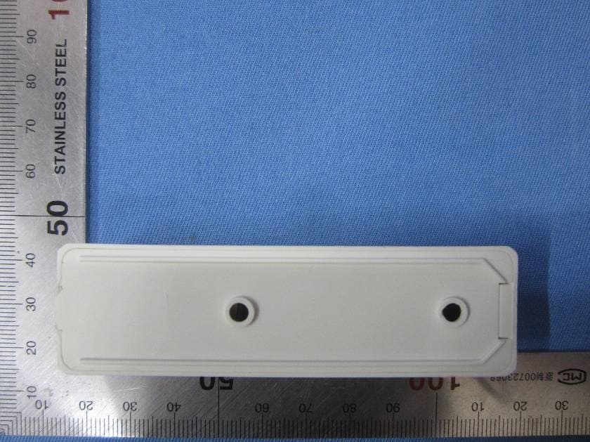
TXL3301
May 08, 2015Wireless Doorbell Chime Sensor
Equipment Class
DSC - Part 15 Security/Remote Control Transmitter
TXL3551
May 08, 2015Wireless Entry Alert Sensor
Equipment Class
DSC - Part 15 Security/Remote Control Transmitter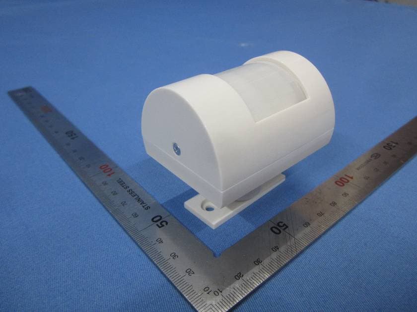
TXL3601
May 08, 2015Wireless Motion-Activated Sensor
Equipment Class
DSC - Part 15 Security/Remote Control Transmitter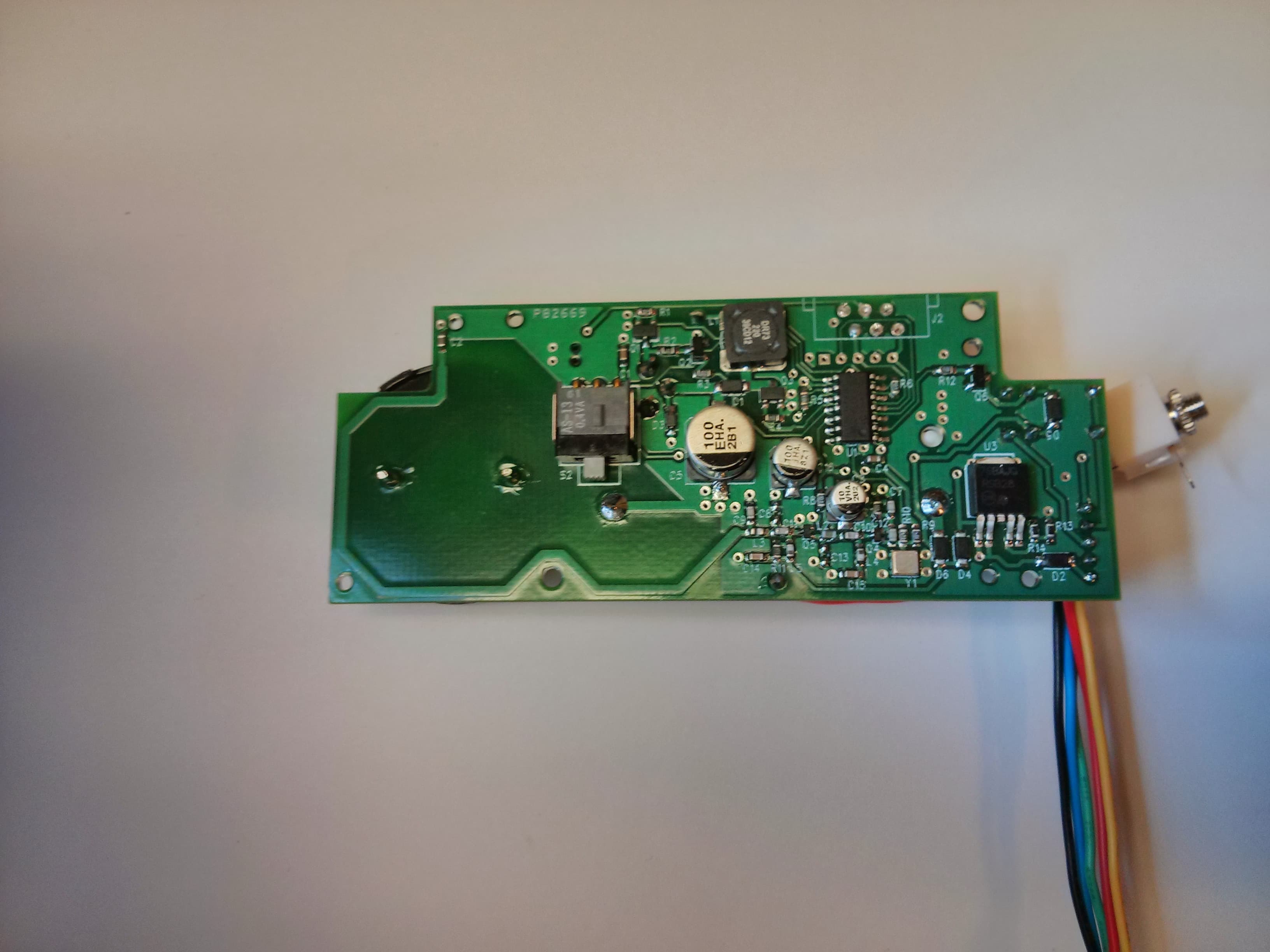
TXL34080
Jan 07, 2014Transmitter for use in a wireless alert system
Equipment Class
DSC - Part 15 Security/Remote Control Transmitter