TXL34080Transmitter for use in a wireless alert system
Safety Technology International, Inc.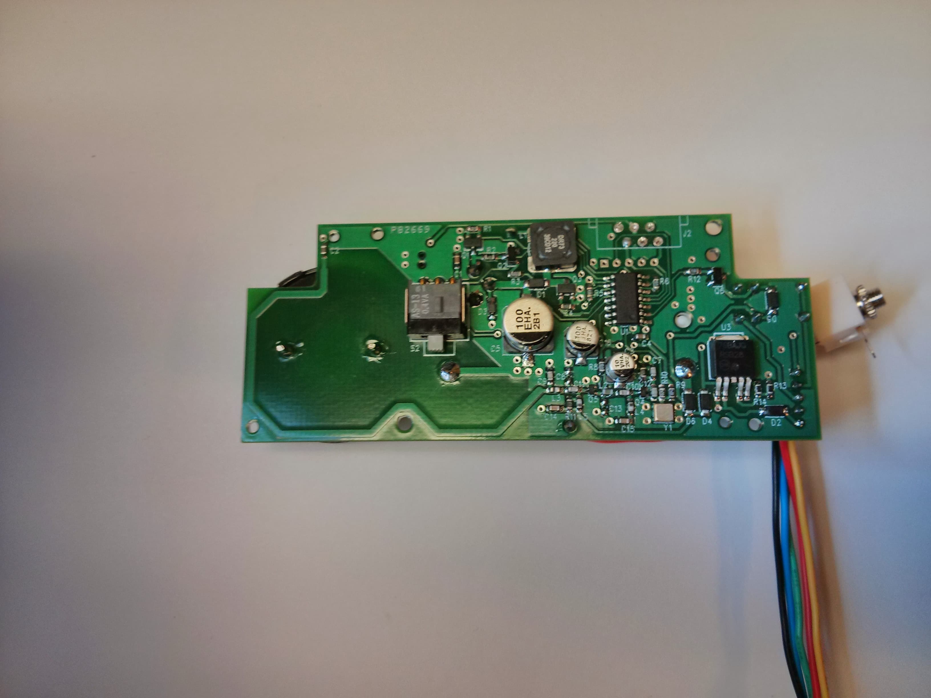
Click to zoom
Application Details
- Equipment Class
- DSC - Part 15 Security/Remote Control Transmitter
- Date of Grant
- Jan 07, 2014
- Application Purpose
- Original Equipment
- Date of Application
- Jan 05, 2014
- Equipment Note
- Transmitter for use in a wireless alert system
- Frequency Range
- 433.92000000 - 433.92000000
- Country
- United States
Documents & Files
Document Text
Text extracted from the exhibit documents filed with the FCC. Open a document above to read the original.
Users Manual
Rhein Tech Laboratories, Inc. Client: STI 360 Herndon Parkway Model: STI-34080 Suite 1400 Standards: FCC 15.231/IC RSS-210 Herndon, VA 20170 ID’s: TXL34080/6335A-34080 http://www.rheintech.com Report #: 2013282 26 of 29 Appendix L: Manual Please refer to the following pages. STI (Europe) - Unit 49G Pipers Road, Park Farm Ind. Estate, Redditch, Worcs. UK Tel: +44 (0) 1527 520999 - Fax: +44 (0) 1527 501999 [email protected] - www.sti-europe.com STI (Europe) - Spain C/La Union 25, Altea, Alicante, Espana Telefono/Fax: +34 966 880785 - Movil: +34 664 828977 [email protected] - www.sti-europe.es STI, Inc. - 2306 Airport Rd., Waterford, Michigan 48237, USA Tel: 248-673-9898 - Fax: 248-673-1246 [email protected] - www.sti-usa.com Euro Stopper ® STI-15000 Series The Euro Stopper is a sleek protective cover that offers protection against tampering, vandalism and damage from accidental activation. Specifications • Input power 3V Lithium CR123A, 12-24 VDC - remote power • Flammability: UL94 V-2 • Temperature range: · Polycarbonate Rated: -40° to 121°C (-40° to 250°F) · Electronics Operating Range: -10° to 49°C (14 to 120° F) · Note: below -10°C a remote power source is recommended Mounting Instructions 1. Position the Euro Stopper ® over the device to be protected, open the front cover of the Euro Stopper ® and mark the position for the four (4) mounting screws. 2. Drill holes and attach the Euro Stopper ® to the wall using the screws provided. See Fig. 1 for drill sizes. 3. If a surface spacer is included, ensure the isolated (inner) mounting columns are at the top (Fig. 2). Note: The spacer is not reversible; arrows are marked upwards on the removable plastic windows for your convenience (Fig. 2). WHEN USING ANCHORS, DRILL 1/4 in. (7mm) DIA. HOLES 1 1/4 in. (31.75mm) DEEP IF USING SCREWS ONLY, DRILL 9/64 in. (3.5mm) DIA. HOLES 1 1/4 in. (31.75mm) DEEP EURO STOPPER ASSEMBLY SCREWS (4) PROVIDED 32mm SPACER ANCHORS (4) PROVIDED WINDOW FOR SPACER (2) PROVIDED WINDOW FOR CONDUIT 4. The 32mm (1.25”) and 50mm (2”) surface spacer provides cable entry facilities for conduit, cable and trunking. 5. For surface installations, use the windows attached to the spacer to fill in any unused cable/conduit entry points. MOUNTING COLUMNS Fig. 1 Fig. 2 86mm (3.4 in.) TEXT HERE 152mm (6 in.) Circuit Board Operations 1. On initial installation, activate the battery by removing the battery cover using a small Phillips screwdriver. Remove red tape. 2. To adjust the volume using the Hi/OFF/Lo switch, remove horn case (see Fig. 4 for location). 3. If using 12/24VDC & Relay Cord: a. Remove horn case or keep off after adjusting volume. b. Remove PCB by removing the two (2) screws as shown in Fig. 5. Lift PCB as far as the wires allow. c. Drill a 5mm hole (3/16”) at the witness point shown on Fig. 5. d. Then insert the wire harness cord into the socket as shown in Fig. 5. e. Leaving a small amount of slack, push the harness into the drilled outlet hole. f. Secure PCB into place and reattach horn case with two (2) provided screws. g. CAUTION: The relay will not operate with the service pin in place. Fig. 3 Alarm Current: 3V Battery 12V 24V Volume - Standby 10μA 500μA 550μA Distance 1M (3 Ft) 3M (10 Ft) - Low 40mA 38mA 22mA Low 72 dB 64 dB - High 105mA 125mA 95mA High 96 dB 88 dB Wire Description RED + REMOTE INPUT Form “C” BLACK - POWER 12-24VDC Dry Contact Relay BLUE COMMON - 30VDC, 1A GREEN NC: NORMALLY CLOSED - 125VAC, 0.5A YELLOW NO: NORMALLY OPEN - 60VDC, 0.3A 12/2013 } } SERVICE PIN (1) PROVIDED M276 HORN CASE 34080 PCB SOUNDER #4 x .312 in. HI-LOW SCREW (2) PROVIDED #2 x .25 in. SMS (2) PROVIDED M272 HORNSHELL VOLUME SWITCH HI/OFF/LO Fig. 4 STI (Europe) - Unit 49G Pipers Road, Park Farm Ind. Estate, Redditch, Worcs. UK Tel: +44 (0) 1527 520999 - Fax: +44 (0) 1527 501999 [email protected] - www.sti-europe.com STI (Europe) - Spain C/La Union 25, Altea, Alicante, Espana Telefono/Fax: +34 966 880785 - Movil: +34 664 828977 [email protected] - www.sti-europe.es STI, Inc. - 2306 Airport Rd., Waterford, Michigan 48237, USA Tel: 248-673-9898 - Fax: 248-673-1246 [email protected] - www.sti-usa.com SERVICE PIN (1) PROVIDED #2 x .25 in. SMS M277 BATTERY COVER CR123A BATTERY Fig. 6 Optional Wireless Transmitter Version 1. The supervised wireless sounder version is capable of transmitting a 433MHz alert to any STI Receiver (range up to 500 ft.) 2. When lifting the cover, the wireless Euro Stopper ® will send an alert to an STI receiver. For enrolling this device, refer to STI receiver installation instructions. 3. On closing the cover, the wireless Euro Stopper ® will send a restore signal to an STI receiver. 4. CAUTION: This device will transmit an alert even with the service pin in place. Replacing the Battery 1. The Euro Stopper ® sounder will emit an audible beep when the battery becomes low. 2. Lift cover and insert the service pin. 3. Using a small Phillips screwdriver, remove the battery cover. 4. Replace 3V CR123A Lithium battery, taking care to observe the polarity as marked. 5. Reassemble the battery cover and screws, then remove the service pin to arm. Optional Break Seals 1. There are two (2) locking tabs, one (1) on each side of the frame. Choose which side the break seal is to be located, close the cover and carefully drill a 3mm (.118”) diameter hole at the witness point. 2. Once the device is ready to be protected, remove the service pin (if applicable), close the cover and lock the break seal in place. A A BB 104mm (4.11 in.) 185mm (7.30 in.) 135mm (5.30 in.) 32mm (1.25 in.) 37mm (1.45 in.) 94mm (3.70 in.) 114mm (4.50 in.) C C DD 104mm (4.11 in.) 135mm (5.30 in.) 185mm (7.30 in.) 32mm (1.26 in.) 58mm (2.30 in.) 63mm (2.48 in.) 68mm (2.68 in.) 94mm (3.70 in.) 115mm (4.53 in.) C C DD 135mm (5.30 in.) 185mm (7.30 in.) 1.4mm (4.11 in.) 50mm (1.97 in.) 76mm (3 in.) 81mm (3.2 in.) 86mm (3.39 in.) 94mm (3.70 in.) 116mm (14.56 in.) A A BB 104mm (4.11 in.) 185mm (7.30 in.) 135mm (5.30 in.) 32mm (1.25 in.) 37mm…
Text truncated - open the document above for the full version.
Users Manual
Rhein Tech Laboratories, Inc. Client: STI 360 Herndon Parkway Model: STI-34080 Suite 1400 Standards: FCC 15.231/IC RSS-210 Herndon, VA 20170 ID’s: TXL34080/6335A-34080 http://www.rheintech.com Report #: 2013282 26 of 29 Appendix L: Manual Please refer to the following pages. STI (Europe) - Unit 49G Pipers Road, Park Farm Ind. Estate, Redditch, Worcs. UK Tel: +44 (0) 1527 520999 - Fax: +44 (0) 1527 501999 [email protected] - www.sti-europe.com STI (Europe) - Spain C/La Union 25, Altea, Alicante, Espana Telefono/Fax: +34 966 880785 - Movil: +34 664 828977 [email protected] - www.sti-europe.es STI, Inc. - 2306 Airport Rd., Waterford, Michigan 48237, USA Tel: 248-673-9898 - Fax: 248-673-1246 [email protected] - www.sti-usa.com Euro Stopper ® STI-15000 Series The Euro Stopper is a sleek protective cover that offers protection against tampering, vandalism and damage from accidental activation. Specifications • Input power 3V Lithium CR123A, 12-24 V , remote power • Flammability: UL94 V-2 • Temperature range: · Polycarbonate Rated: -40° to 121°C (-40° to 250°F) · Electronics Operating Range: -10° to 49°C (14 to 120° F) Mounting Instructions 1. Position the Euro Stopper ® over the device to be protected, open the front cover of the Euro Stopper ® and mark the position for the four (4) mounting screws. 2. Drill holes and attach the Euro Stopper ® to the wall using the screws provided. See Fig. 1 for drill sizes. 3. If a surface spacer is included, ensure the isolated (screw) mounting columns are at the top (Fig. 2). Note: The spacer is not reversible; arrows are marked upwards on the removable plastic windows for your convenience (Fig. 2). WHEN USING ANCHORS, DRILL 3/16 in. (5mm) DIA. HOLES 1 1/4 in. (31.75mm) DEEP IF USING SCREWS ONLY, DRILL 1/8 in. (30mm) DIA. HOLES 1 1/4 in. (32mm) DEEP EURO STOPPER ASSEMBLY SCREWS (4) PROVIDED SPACER ANCHORS (4) PROVIDED WINDOW FOR SPACER (2) PROVIDED WINDOW FOR CONDUIT (2) PROVIDED 4. The 32mm (1.25”) and 50mm (2”) surface spacer provides cable entry facilities for conduit, cable and trunking. 5. For surface installations, use the windows attached to the spacer to fill in any unused cable/conduit entry points. MOUNTING COLUMNS Fig. 1 Fig. 2 86mm (3.40 in.) TEXT HERE 152mm (6.00 in.) Circuit Board Operations 1. On initial installation, activate the battery by removing the battery cover using a small Phillips screwdriver. Remove red tape. 2. To adjust the volume using the Hi/OFF/Lo switch, remove horn case (see Fig. 4 for location). 3. If using 12/24VDC & Relay Cord: a. Remove horn case. b. Remove PCB by removing the two (2) screws as shown in Fig. 5. Lift PCB as far as the wires allow. c. Drill a 5mm hole (3/16”) at the witness point shown on Fig. 5. d. Then insert the wire harness cord into the socket as shown in Fig. 5. e. Leaving a small amount of slack, push the harness into the drilled outlet hole. f. Secure PCB into place and reattach horn case with two (2) provided screws. g. CAUTION: The relay and sounder will not operate with the service pin in place. Fig. 3 Alarm Current: 3V Battery 12V 24V Volume - Standby 10μA 500μA 550μA Distance 1M (3 Ft) 3M (10 Ft) - Low 40mA 38mA 22mA Low 72 dB 64 dB - High 105mA 125mA 95mA High 96 dB 88 dB Wire Description RED + REMOTE INPUT Form “C” BLACK - POWER 12-24V Dry Contact Relay BLUE COMMON 30VDC, 1A GREEN NC: NORMALLY CLOSED 125VAC, 0.5A YELLOW NO: NORMALLY OPEN 60VDC, 0.3A 15000 series 2013_12 } } SERVICE PIN (1) PROVIDED M276 HORN CASE 34080 PCB SOUNDER #4 x .312 in. HI-LOW SCREW (2) PROVIDED #2 x .25 in. SMS (2) PROVIDED M272 HORNSHELL VOLUME SWITCH HI/OFF/LO Fig. 4 STI (Europe) - Unit 49G Pipers Road, Park Farm Ind. Estate, Redditch, Worcs. UK Tel: +44 (0) 1527 520999 - Fax: +44 (0) 1527 501999 [email protected] - www.sti-europe.com STI (Europe) - Spain C/La Union 25, Altea, Alicante, Espana Telefono/Fax: +34 966 880785 - Movil: +34 664 828977 [email protected] - www.sti-europe.es STI, Inc. - 2306 Airport Rd., Waterford, Michigan 48237, USA Tel: 248-673-9898 - Fax: 248-673-1246 [email protected] - www.sti-usa.com SERVICE PIN (1) PROVIDED #2 x .25 in. SMS M277 BATTERY COVER CR123A BATTERY Fig. 6 Optional Wireless Transmitter Version 1. The supervised wireless sounder version is capable of transmitting a 433MHz alert to any STI Receiver (range up to 1000 ft.) 2. When lifting the cover, the wireless Euro Stopper ® will send an alert to an STI receiver. For enrolling this device, refer to STI receiver installation instructions. 3. On closing the cover, the wireless Euro Stopper ® will send a restore signal to an STI receiver. 4. CAUTION: This device will transmit an alert even with the service pin in place. Replacing the Battery 1. The Euro Stopper ® sounder will emit an audible beep when the battery becomes low. 2. Lift cover and insert the service pin. 3. Using a small Phillips screwdriver, remove the battery cover. 4. Replace 3V CR123A Lithium battery, taking care to observe the polarity as marked. 5. Reassemble the battery cover and screws, then remove the service pin to arm. Optional Break Seals 1. There are two (2) locking tabs, one (1) on each side of the frame. Choose which side the break seal is to be located, close the cover and carefully drill a 3mm (.118”) diameter hole at the witness point. 2. Once the device is ready to be protected, remove the service pin (if applicable), close the cover and lock the break seal in place. A A BB 104mm (4.11 in.) 185mm (7.30 in.) 135mm (5.30 in.) 32mm (1.25 in.) 37mm (1.45 in.) 94mm (3.70 in.) 114mm (4.50 in.) C C DD 104mm (4.11 in.) 135mm (5.30 in.) 185mm (7.30 in.) 32mm (1.26 in.) 58mm (2.30 in.) 63mm (2.48 in.) 68mm (2.68 in.) 94mm (3.70 in.) 115mm (4.53 in.) C C DD 135mm (5.30 in.) 185mm (7.30 in.) 1.4mm (4.11 in.) 50mm (1.97 in.) 76mm (3.00 in.) 81mm (3.20 in.) 86mm (3.39 in.) 94mm (3.70 in.) 116mm (14.56 in.) A A BB 104mm (4.11 in.) 185mm (7.30 in.) 135mm (5.30 in.) 32mm (1.25 in.) 37mm (1.45 in.) 94mm (3.70 in.) 114mm (4.50 in.) C C DD 104mm (4.11 …
Text truncated - open the document above for the full version.
Cover Letter(s)
Rhein Tech Laboratories, Inc. Client: STI 360 Herndon Parkway Model: STI-34080 Suite 1400 Standards: FCC 15.231/IC RSS-210 Herndon, VA 20170 ID’s: TXL34080/6335A-34080 http://www.rheintech.com Report #: 2013282 15 of 29 Appendix A: FCC/TCB Agency Authorization Letter Please refer to the following page. Safety Technology International, Inc. Authoritv to Act as Aqent Date: 26 Dec. 2013 American Certification Body, Inc. 6731 Whittier Avenue Suite C110 Mclean, VA 22101 To Whom lt May Concern: Rhein Tech Laboratories, lnc. is authorized to act on our behalf, until otheruise notified, for applications to American Certification Body, Inc. (ACB). We certiry that we are not subject to denial of federal benefits, that includes FCC benefits, pursuant to Section 5301 of the AntFDrug Abuse Act of 1988, 21 U.S.C. 862. Further, no party, as defined in 47 CFR 1.2002 (b), to the application is subject to denial of federal beneflts, that includes FCC benefits. Thank vou. Agency Agreement Date: 26 Dec. 2014 (Typically 8 - 12 months) 2306 Airport Road Tel: (248) 673-9898 Waterford, lvlichigan Faxi (248J 673'1246 48327-1209 John Tavlor (Print name) By: Title: On behalf of: Safetv Technoloqv International. lnc. (Company Name) Telephone: 248€73-9898 Executive Vice President
Cover Letter(s)
Rhein Tech Laboratories, Inc. Client: STI 360 Herndon Parkway Model: STI-34080 Suite 1400 Standards: FCC 15.231/IC RSS-210 Herndon, VA 20170 ID’s: TXL34080/6335A-34080 http://www.rheintech.com Report #: 2013282 16 of 29 Appendix B: FCC Confidentiality Request Letter Please refer to the following page. 2306 AF@rt Foad T6l: (248)673-9898 Waterford, lr4ichigan Faxi (248) 673-1246 48327,1209 Safety Technology International, Inc. Da'€: 26 Dec, 2013 American Certification Body, Inc. 6731 VVhittier Avenue Suite C110 Mclean, VA 22101 To Whom lt May Concern: The following information is to be held confidential pursuant to FCC 47 CFR S0.457(d) and 50.459, because the information provided contains trade secrets and is proprietary. lf made public, the information might be used to the disadvantage ofthe applicant in the market place. . Schematics . Technical Product DescriDtion . Block Diagram ,81fi'&relv, / t'1 tU,^&/--- //ohn Taylor ' ' Executive Vice President Confidential
Cover Letter(s)
Rhein Tech Laboratories, Inc. Client: STI 360 Herndon Parkway Model: STI-34080 Suite 1400 Standards: FCC 15.231/IC RSS-210 Herndon, VA 20170 ID’s: TXL34080/6335A-34080 http://www.rheintech.com Report #: 2013282 17 of 29 Appendix C: FCC Limited Modular Approval Please refer to the following page. December 23,2013 RE: STI-34080 Request for Limited Modular Approval To Whom lt May Concern: We hereby request Limited Modular Approval for TXL34080 as described under 47 CFR 15.212(b). This device is usable only on limited Safety Technology International, Inc. hosts. The following pages describe the compliance with this device with the requirements. Sincerely, A,fuz /)6hnTaylor Safety Technology International, Inc. Applicant/Grantee Safety Technolory International, Inc. FCC ID: TXL34080 Section 15.212 Modular Transmitters Request for Modular Approval | ! | Request for Limited Modular Approval X RequirementsEUT Conditions Complv (Y/f.l ) Sinqle Modular Approval Requirements I The radio elements of the modular transmitter must have their own shielding. The physical crystal and tuning capacitors may be located extemal to the shielded radio elements. Not required for LMA Y 2The modular transmitter must have buffered modulation/data inputs (if such inputs are provided) to ensure that the module will comply with Part 15 requirements under conditions of excessive data rates or over-modulation. N/A - These inputs are not provided Y 3The modular transmitter must have its o\4n power supply regulation. Not reouired for LMA Y A The modular transmitter must comply with the antenna and lransmission The antenna is permanently attached since it is a PCB trace. Y system requirements of Sections 15.203, 15.204(b) and 15.204(c). The antenna must either be permanently attached or employ a 'lmique" antenna coupler (at all connections between the rnodule and the antenna, including the cable). The ' professional installation" provision of Section 15.203 is not applicable to modules but can apply to limited modular approvals rmder paragraph (b) of this section. 5 The modular transmitter must be tested in a stand-alone configuration, Le., the module must not be inside another device during testing for compliance with Part 15 requirements. Unless the transmitter module will be battery powered, it must comply with the AC line conducted requirements found in Section 15.207. AC or DC power lines and data inpuVoutput lines connected to the module must not contain ferrites, unless they will be marketed with the module (see Section 15.27(a)). The length of these lines shall be the length typical of actual use or, if that length is unknown, at least 10 centimeters to insure that there is no coupling between the case ofthe module and supporting equipment. Any accessories, peripherals, or support equipment connected to the module during testing shall be unmodified and commercially available (see Section 15.3 1(i)). Not required for LMA. As specified in 15.212(b), the manufacturer must only "demonstrate by alternative means in the application for equipment authorization that the modular transmitter meets all the applicable Part 15 requirements under the operating conditions in which the transmitter will be used." We have done this by testing the device in the host with which it will be used. Y 6 The modular transmitter must be equipped with either a permanently affixed label or must be capable of elechonically displaying its FCC identification number. (A) If using a permanently affaed label, the modular trqnsmitter must be labeled with its own FCC identiJication number, and, ifthe FCC identificqtion number is not visible when the module is installed inside another device, then the outside ofthe device into which the module is installed must also display a label referring to the enclosed module. This efierior label can use wording such as the following: "Contains Transmitter Module FCC ID: XYZMODELI " or "Contains FCC ID: XYZMODELI. " Any similar wording that expresses the same meaning may be used. The Grantee mqy either provide such a label, an example ofwhich must be included in the app Ii cat i on for e quipm ent quthorizqtion, o\ must provide adequate instructions qlong with the module which acplain this requirement. In the latter cqse, a copy of these instructions must be included in the application for equipment authorizdtion. (B) If the modular transmitter uses an electronic display ofthe FCC identilication number, the information must be readily accessible and visible on the modular transmitter or on the device in which it is installed. Ifthe module is installed inside another device, then the outside ofthe device into which the module is instqlled A FCC label shall be affixed to the module. Any host containing the module will has have a label. Please see the Label Photos which show this. Y uust displqy q label referring to the enclosed module. This exterior label can use wording such as thefollowing: " Contains FCC certifed transmitter module(s). " Any similar wording that expresses the same meaning may be used, The user manuql must include instructions on how to access the electronic display. A cory ofthese instructions must be included in the application for e q uiDm e nt aut h or iz at i on. 7 The modular transmitter must comply with any speciflc rules or operating requirements that ordinarily apply to a complete transmitter and the manufacturer must provide adequate instructions along with the module to explain any such requirements. A copy of these instructions must be included in the application for equipment auth orizatiorl We have provided instructions in the usef manual. Y 8 The modular hansmitter must comply with any applicable RF exposure requirements in its final configuration. N/A - this device is not meant to be used near the body Y A limited nodular approval may be granted for single or split modular hansmitters that do not comply with all of the above requirements, e.g, shielding, minimum signaling amplitude…
Text truncated - open the document above for the full version.
External Photos
Rhein Tech Laboratories, Inc. Client: STI 360 Herndon Parkway Model: STI-34080 Suite 1400 Standards: FCC 15.231/IC RSS-210 Herndon, VA 20170 ID’s: TXL34080/6335A-34080 http://www.rheintech.com Report #: 2013282 28 of 29 Appendix N: External Photographs Please refer to the following pages. MODEL: STI-34080 FCC ID: TXL34080 IC: 6335A-34080 Internal Pictures Safety Technology International, Inc.12-19-13 Safety Technology International, Inc.12-19-13 November 21, 2013Safety Technology International, Inc.Page | 3 Sample Host
External Photos
Rhein Tech Laboratories, Inc. Client: STI 360 Herndon Parkway Model: STI-34080 Suite 1400 Standards: FCC 15.231/IC RSS-210 Herndon, VA 20170 ID’s: TXL34080/6335A-34080 http://www.rheintech.com Report #: 2013282 28 of 29 Appendix N: External Photographs Please refer to the following pages. MODEL: STI-34080 FCC ID: TXL34080 IC: 6335A-34080 Safety Technology International, Inc.12-19-13 Safety Technology International, Inc.12-19-13 November 21, 2013Safety Technology International, Inc.Page | 3 Sample Host
ID Label/Location Info
Rhein Tech Laboratories, Inc. Client: STI 360 Herndon Parkway Model: STI-34080 Suite 1400 Standards: FCC 15.231/IC RSS-210 Herndon, VA 20170 ID’s: TXL34080/6335A-34080 http://www.rheintech.com Report #: 2013282 22 of 29 Appendix H: ID Label and Location Please refer to the following pages for the ID label sample and host label sample. MODEL: STI-34080 FCC ID: TXL34080 IC: 6335A-34080 Label Pictures Safety Technology International, Inc.12-23-13 Safety Technology International, Inc.12-23-13 Safety Technology International, Inc.12-23-13
ID Label/Location Info
Rhein Tech Laboratories, Inc. Client: STI 360 Herndon Parkway Model: STI-34080 Suite 1400 Standards: FCC 15.231/IC RSS-210 Herndon, VA 20170 ID’s: TXL34080/6335A-34080 http://www.rheintech.com Report #: 2013282 22 of 29 Appendix H: ID Label and Location Please refer to the following pages for the ID label sample and host label sample. MODEL: STI-34080 FCC ID: TXL34080 IC: 6335A-34080 Host Label Photograph Safety Technology International, Inc.1-8-14 Safety Technology International, Inc.1-8-14 Host Label Location Safety Technology International, Inc.1-8-14 ID Label on Module
Internal Photos
Rhein Tech Laboratories, Inc. Client: STI 360 Herndon Parkway Model: STI-34080 Suite 1400 Standards: FCC 15.231/IC RSS-210 Herndon, VA 20170 ID’s: TXL34080/6335A-34080 http://www.rheintech.com Report #: 2013282 29 of 29 Appendix O: Internal Photographs Please refer to the following pages. MODEL: STI-34080 FCC ID: TXL34080 IC: 6335A-34080 Safety Technology International, Inc.12-19-13 Safety Technology International, Inc.12-19-13
Test Report
Engineering Solutions & Electromagnetic Compatibility Services 360 Herndon Pkwy | Suite 1400 | Herndon | Virginia 20170 Phone: 703.689.0368 | Fax: 703.689.2056 | www.rheintech.com FCC Part 15.231 & IC RSS-210 Certification Application Report Limited Modular Approval Test Lab: Rhein Tech Laboratories, Inc. Tel: 703-689-0368 360 Herndon Parkway Fax: 703-689-2056 Suite 1400 Web: www.rheintech.com Herndon, VA 20170 Applicant: Safety Technology International, Inc. (STI) 2306 Airport Road Waterford, MI 48327 Contact: John Taylor FCC ID IC TXL34080 6335A-34080 Test Report Date December 20, 2013 Platform N/A RTL Work Order Number 2013282 Model STI-34080 RTL Quote Number QRTL13-282 FCC Classification DSC – Part 15 Security/Remote Control Transmitter FCC Rule Part(s) Part 15.231: Periodic operation in the band 40.66 – 40.70 MHz and above 70 MHz (10-01-12) IC Standard RSS-210 Issue 8: Licence-exempt Radio Apparatus (All Frequency Bands): Category I Equipment Procedure or Other Guidance ANSI C63.4-2003 Standard for Methods of Measurement of Radio-Noise Emissions Digital Interface Information N/A Frequency Range (MHz) Output Power (W) Frequency Tolerance Emission Designator 433.92 N/A N/A 55K4P1D I, the undersigned, hereby declare that the equipment tested and referenced in this report conforms to the identified standard(s) as described in this test report. Modifications made to the equipment during testing in order to achieve compliance with these standards are listed in the report. Furthermore, there was no deviation from, additions to, or exclusions from the applicable parts of FCC Part 2, FCC Part 15, IC RSS- 210 and ANSI C63.4. Signature: Date: December 20, 2013 Typed/Printed Name: Desmond A. Fraser Position: President This report may not be reproduced, except in full, without the written approval of Rhein Tech Laboratories, Inc. and Safety Technology International, Inc. The test results reported relate only to the item tested. These tests are accredited and meet the requirements of ISO/IEC 17025 as verified by ANSI-ASQ National Accreditation Board/ACLASS. Refer to certificate and scope of accreditation AT-1445. Rhein Tech Laboratories, Inc. Client: STI 360 Herndon Parkway Model: STI-34080 Suite 1400 Standards: FCC 15.231/IC RSS-210 Herndon, VA 20170 ID’s: TXL34080/6335A-34080 http://www.rheintech.com Report #: 2013282 2 of 29 Table of Contents 1 General Information ............................................................................................................................... 4 1.1 Scope ............................................................................................................................................ 4 1.2 Modifications ................................................................................................................................. 4 1.3 Test Facility ................................................................................................................................... 4 1.4 Related Submittal(s)/Grant(s) ....................................................................................................... 4 2 Test Information .................................................................................................................................... 4 2.1 Test Justification ........................................................................................................................... 4 2.2 Exercising the EUT ....................................................................................................................... 4 2.3 Test Result Summary .................................................................................................................... 5 2.4 Test System Details ...................................................................................................................... 5 2.5 Configuration of Tested System .................................................................................................... 5 3 Duty Cycle Calculation - FCC 15.35(c) ................................................................................................. 6 4 Transmitter Deactivation – FCC 15.231(a)(1) ....................................................................................... 8 5 Modulated Bandwidth – FCC 15.231(c), RSS-210 A1.1.3 .................................................................... 9 5.1 Modulated Bandwidth Test Procedure .......................................................................................... 9 5.2 FCC 15.231(c) Limits .................................................................................................................... 9 5.3 Modulated Bandwidth Test Data ................................................................................................... 9 6 Radiated Emissions – FCC 15.209, 15.231(b).................................................................................... 11 6.1 Radiated Fundamental Emissions Test Procedure..................................................................... 11 6.1.1 Radiated Fundamental Emissions Limits Test Data ............................................................... 11 6.2 Radiated Harmonics/Spurious Emissions – FCC 15.231(b) ....................................................... 11 6.2.1 Radiated Emissions Harmonics/Spurious Test Procedure ..................................................... 11 7 Conducted Emissions .......................................................................................................................... 14 7.1 Site and Test Description ............................................................................................................ 14 7.2 Test Limits ................................................................................................................................... 14 7.3 Conducted Emissions Test Results ............................................................................................ 14 8 Con…
Text truncated - open the document above for the full version.
Test Setup Photos
Rhein Tech Laboratories, Inc. Client: STI 360 Herndon Parkway Model: STI-34080 Suite 1400 Standards: FCC 15.231/IC RSS-210 Herndon, VA 20170 ID’s: TXL34080/6335A-34080 http://www.rheintech.com Report #: 2013282 27 of 29 Appendix M: Test Photographs Photograph 1: Radiated Emissions
Contact Information
Applicant
John F. Taylor(Executive Vice President)
Technical Contact
Rhein Tech LabsRick McMurray
[email protected]7036890368
360 Herndon Parkway · Herndon, Virginia · United States
Test Firm
Rhein Tech Laboratories, Inc.Richard McMurray
Technical Specifications
| # | Rule Parts | Frequency Range | Power Output |
|---|---|---|---|
| 1 | 15.231 | 433.92 MHz - 433.92 MHz | - |
Other Applications from Safety Technology International, Inc.
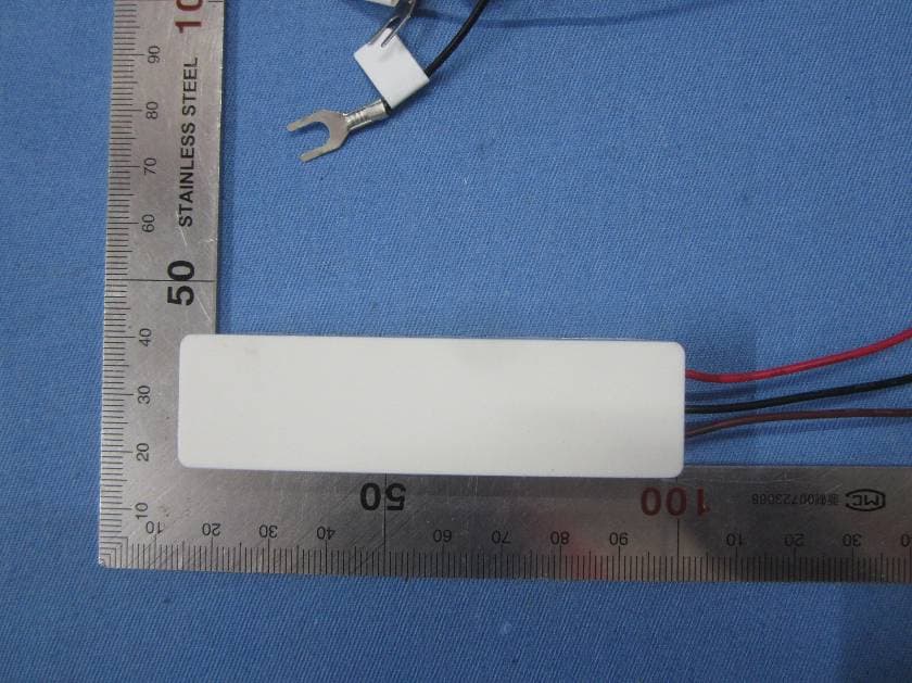
TXL3331
Jun 20, 2015Wireless Doorbell Extender
Equipment Class
DSC - Part 15 Security/Remote Control Transmitter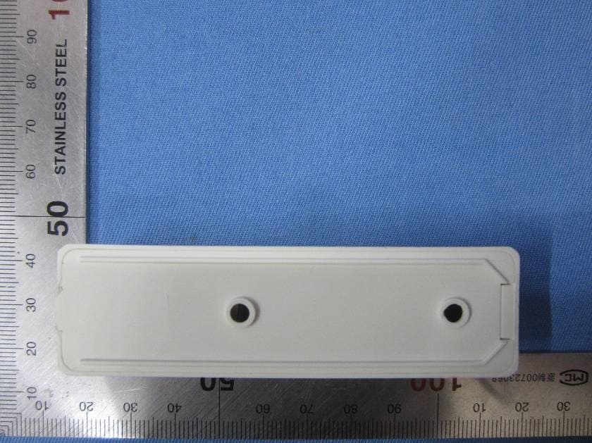
TXL3301
May 08, 2015Wireless Doorbell Chime Sensor
Equipment Class
DSC - Part 15 Security/Remote Control Transmitter
TXL3551
May 08, 2015Wireless Entry Alert Sensor
Equipment Class
DSC - Part 15 Security/Remote Control Transmitter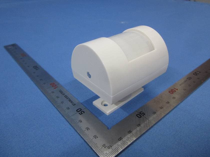
TXL3601
May 08, 2015Wireless Motion-Activated Sensor
Equipment Class
DSC - Part 15 Security/Remote Control Transmitter
TXL34751
Apr 14, 2013Outdoor Motion Detector, 433.92MHz
Equipment Class
DSC - Part 15 Security/Remote Control Transmitter