TXL34066Remote Control
Safety Technology International, Inc.
Click to zoom
Application Details
- Equipment Class
- DSC - Part 15 Security/Remote Control Transmitter
- Date of Grant
- Nov 25, 2010
- Application Purpose
- Original Equipment
- Date of Application
- Nov 23, 2010
- Equipment Note
- Remote Control
- Frequency Range
- 433.92000000 - 433.92000000
- Country
- United States
Documents & Files
Document Text
Text extracted from the exhibit documents filed with the FCC. Open a document above to read the original.
Users Manual
INSTALLATION OF STI-6517SW STI STOPPER ® STATION SHIELD AND SOUNDER WITH WIRELESS All specifications and information shown were current as of publication and are subject to change without notice. 6517SW AUG2010 ® Safety Technology International, Inc. 2306 Airport Road • Waterford, Michigan 48327-1209 Phone: 248-673-9898 • Fax: 248-673-1246 Toll Free: 800-888-4784 • E-mail: [email protected] Web: www.sti-usa.com Safety Technology International (Europe) Ltd. Unit 49G Pipers Road • Park Farm Industrial Estate • Redditch Worcestershire • B98 0HU • England • Tel: 44 (0) 1527 520 999 Fax: 44 (0) 1527 501 999 • Freephone: 0800 085 1678 (UK only) E-mail: [email protected] • Web: www.sti-europe.com INSTALLATION: 1. Rotate the button lever clockwise to the stop (as shown) so it is pointed toward the inside of the Stopper Station Shield. 2. With shield rotated to open position (approximately 90° to cover), insert shield pivots into slots on Stopper Station cover. 3. If desired, insert wires from device switch into PCB terminals and tighten screws. 4. Place the volume jumper for desired sounder volume (see above). 5. Insert PCB fully into PCB guides. Be sure switch wires are not routed over the battery or button. 6. Rotate cover to closed position. 7. Rotate cover to fully open position then back to closed position to ensure the Button Lever is pressed down onto the button. (If not, remove PCB and repeat steps 5 and 6.) 8. Pull off the plastic battery tab, leaving the battery installed. (Sounder will be active at this point.) 9. Mount cover with shield onto contact assembly. 10. Install bottom screw to hold cover to contact assembly. WIRELESS OPERATION: The STI Stopper Station with wireless alert will send two separate wireless signals to an STI Receiver. If both signals are to be used, each signal must be individually enrolled into the receiver. The first is the Stopper Station cover signal. This signal is transmitted when the cover is opened and restores the signal to normal when the cover is closed. The second is the terminal signal. A separate alert signal is sent when the terminals have a short or closed circuit between them and restores the signal to normal when the short is removed or an open circuit. To enroll the wireless device signal into the receiver, please see the receiver installation instructions. A 123 4 4 A DRAWN bhodges CHECKED QA MFG APPROVED 2/2 3/2 010 Safety Technology International, Inc. 2306 Airport Road, Waterford, MI 48327 TITLE SIZE C SCALE DWG NO SS Integral Cover Assembly Install REV SHEET 1 OF 1 Install: 1. Orient the Button Lever so it is pointed toward the inside of the Stopper Station Shield Assembly. 2. With Shield Rotated to open position (Approximately 90 to Cover), insert Shield Pivots into Stopper Station Cover slots. 3. If desired, insert wires from device switch into PCB terminals and tighten screws. 4. Place the volume jumper for desired sounder volume. (See picture) 5. Insert Stopper Sounder PCB fully into PCB Card Guides. Be sure that switch wires are not routed over the battery or button. 6. Rotate Cover to Closed Position. 7. Rotate Cover to fully open position, back to closed p osition, and ensure the Button Lever is pressed down onto the button. (If not, remove PCB and repeat steps 5 and 6.) 8. Pull off the plastic battery tab with the battery remaining installed. (Sounder will be active at this point) 9. Mount total assembly onto Stopper Station Contact Assembly. 10. Install bottom Screw to Hold Cover to Contact Assembly. SCREW STOPPER STATION CONTACT ASSEMBLY SOUNDER/WIRELESS PCB 123A LITHIUM BATTERY PCB GUIDE COVER MOUNTING SLOTS BUTTON LEVER SHIELD PIVOT STOPPER STATION SHEILD HIGH LOW OFF VIEW A SWITCH TERMINALS (WIRELESS ONLY) VOLUME JUMPER STOPPER STATION COVER A HIGH LOWOFF VIEW A VOLUME JUMPER A 123 4 4 A DRAWN bhodges CHECKED QA MFG APPROVED 2/2 3/2 010 Safety Technology International, Inc. 2306 Airport Road, Waterford, MI 48327 TITLE SIZE C SCALE DWG NO SS Integral Cover Assembly Install REV SHEET 1 OF 1 Install: 1. Orient the Button Lever so it is pointed toward the inside of the Stopper Station Shield Assembly. 2. With Shield Rotated to open position (Approximately 90 to Cover), insert Shield Pivots into Stopper Station Cover slots. 3. If desired, insert wires from device switch into PCB terminals and tighten screws. 4. Place the volume jumper for desired sounder volume. (See picture) 5. Insert Stop per Sounder PCB fully into PCB Card Guides. Be sure that switch wires are not routed over the battery or button. 6. Rotate Cover to Closed Position. 7. Rotate Cover to fully open position, back to closed position, and ensure the Button Lever is pressed down onto the button. (If not, remove PCB and repeat steps 5 and 6.) 8. Pull off the plastic battery tab with the battery remaining installed. ( Sounder will be active at this point) 9. Mount total assembly onto Stopper Station Contact Assembly. 10. Install bottom Screw to Hold Cover to Contact Assembly. SCREW STOPPER STATION CONTACT ASSEMBLY SOUNDER/WIRELESS PCB 123A LITHIUM BATTERY PCB GUIDE COVER MOUNTING SLOTS BUTTON LEVER SHIELD PIVOT STOPPER STATION SHEILD HIGH LOW OFF VIEW A SWITCH TERMINALS (WIRELESS ONLY) VOLUME JUMPER STOPPER STATION COVER A HIGH LOWOFF VIEW A VOLUME JUMPER IMPORTANT NOTICE: Changes or modifications not expressly approved by the manufacturer could void the user’s authority to operate this equipment. This device complies with Part 15 of the FCC rules. Operation is subject to the following two conditions: 1. This device may not cause harmful interference. 2. This device must accept any interference that may be received, including interference that may cause undesired operation. Model: 34066 FCC ID: TXL34066 IC: 6335A-34066 This product meets the applicable Industry Canada technical specifications. Le présent materiel est conforme aux specifications techniques applicables d’Industrie Canada.
Cover Letter(s)
Authority to Act as Agent November 8, 2010 American Telecommunication Certification Body, Inc. 6731 Whittier Avenue Suite C110 McLean, VA 22101 To Whom It May Concern: ______Rob Hendrickson at Resolution Engineering, Inc.______ is authorized to act on our behalf, until otherwise notified, for applications to American Telecommunication Certification Body, Inc. (ATCB). We certify that we are not subject to denial of federal benefits, that includes FCC benefits, pursuant to Section 5301 of the Anti-Drug Abuse Act of 1988, 21 U.S.C. 862. Further, no party, as defined in 47 CFR 1.2002 (b), to the application is subject to denial of federal benefits, that includes FCC benefits. Thank you, Agency Agreement Expiration Date: November 8, 2011 By: __________ John Taylor (Signature) (Print Name) Title: Executive Vice President On behalf of: Safety Technology International, Inc. Telephone: 248-673-9898
Cover Letter(s)
Request for Confidentiality November 8, 2010 Subject: Confidentiality Request for FCC ID: ______TXL-34066_____ Pursuant to FCC 47 CRF 0.457(d) and 0.459 and IC RSP-100, Section 10, the applicant requests that a part of the subject FCC application be held confidential. Type of Confidentiality Requested Exhibit Short Term Permanent Block Diagrams Short Term External Photos Short Term Permanent* 1 Internal Photos Short Term Permanent Operation Description/Theory of Operation Short Term Permanent Parts List & Placement/BOM Short Term Permanent Tune-Up Procedure Short Term Permanent Schematics Short Term Test Setup Photos Short Term Permanent* User’s Manual *Note: Safety Technology International, Inc. has spent substantial effort in developing this product and it is one of the first of its kind in industry. Having the subject information easily available to "competition" would negate the advantage they have achieved by developing this product. Not protecting the details of the design will result in financial hardship. Permanent Confidentiality: The applicant requests the exhibits listed above as permanently confidential be permanently withheld from public review due to materials that contain trade secrets and proprietary information not customarily released to the public. Short-Term Confidentiality: The applicant requests the exhibits selected above as short term confidential be withheld from public view for a period of Not Applicable days from the date of the Grant of Equipment Authorization and prior to marketing. This is to avoid premature release of sensitive information prior to marketing or release of the product to the public. Applicant is also aware that they are responsible to notify ATCB in the event information regarding the product or the product is made available to the public. ATCB will then release the documents listed above for public disclosure pursuant to FCC Public Notice DA 04-1705. Sincerely, By: /Executive Vice President John Taylor (Signature/Title 2 ) (Print name) 1 - The asterisked items (*) require further justification before permanent confidentiality will be allowed. These also currently require review by the FCC under their Permit-But-Ask policy before the grant is issued and can delay completion of an application. Further justification should be added to the note above. One such example for a potted device would be: “The EUT is FULLY potted using a non-removable epoxy based material. Removal of potting material causes irreparable damage to internal circuitry. See photographs exhibits that outline the device before and after potting.” 2 - Must be signed by applicant contact given for applicant on the FCC site, or by the authorized agent if an appropriate authorized agent letter has been provided. Letters should be placed on appropriate letterhead.
Test Report
Safety Technology International, Inc. FCC ID: TXL34066 Certification Test Report 2010-10-04 Contents 1. Introduction ............................................................................................................................................................................. 3 2. Statement of Compliance ..................................................................................................................................................... 3 2.1. FCC Part 2 §2.907 ............................................................................................................................................................ 3 2.2. FCC Part 2 §2.911 ............................................................................................................................................................ 3 2.3. FCC Part 2 §2.913 ............................................................................................................................................................ 3 2.4. FCC Part 2 §2.915 ............................................................................................................................................................ 3 2.5. FCC Part 2 §2.925 ............................................................................................................................................................ 4 2.6. FCC Part 2 §2.943, 2.945 ................................................................................................................................................ 4 2.7. FCC Part 2 §2.947 ............................................................................................................................................................ 4 2.8. FCC Part 2 §2.948 ............................................................................................................................................................ 4 2.9. FCC Part 2 §2.1033 .......................................................................................................................................................... 5 3. Discussion of Laboratory Measurements and Rules Compliance ................................................................................ 6 3.1. FCC Part 15 §15.231(a)(1) ............................................................................................................................................. 6 3.2. FCC Part 15 §15.231(a)(2) ............................................................................................................................................. 6 3.3. FCC Part 15 §15.231(a)(3) ............................................................................................................................................. 6 3.4. FCC Part 15 §15.231(a)(4) ............................................................................................................................................. 6 3.5. FCC Part 15 §15.231(a)(5) ............................................................................................................................................. 6 3.6. FCC Part 15 §15.231(b) .................................................................................................................................................. 6 3.6.1. Raw Field Strength Limits ...................................................................................................................................... 6 3.6.2. Duty Cycle Correction Factor and Resulting Limits ......................................................................................... 7 3.6.3. Measured Radiated Field Strength Data ............................................................................................................ 7 3.7. FCC Part 15 §15.231(c) ................................................................................................................................................... 7 1. Introduction The 34066 is a small battery-powered sensor for use in a wireless alert system. Certification is requested under FCC Rules, Part 15, Subpart C, Paragraph 15.231. 2. Statement of Compliance Specific sections of FCC Rules Part 2 that require information or listing are given below. 2.1.FCC Part 2 §2.907 This is an application for certification of original equipment 2.2.FCC Part 2 §2.911 a)This application has been filed electronically using form 731. b) All required information has been supplied in this application and its attachments. c)This applicant has signed the application electronically. d) The technical test data has been signed by the agency performing the testing. e)Signature supplied in appropriate block on form 731. f)Processing fee has been paid by credit card. g)Signatures have been supplied electronically. 2.3.FCC Part 2 §2.913 a)This application has been filed electronically. b) Appropriate fees have been filed electronically. c)Equipment samples shall be supplied as requested. 2.4.FCC Part 2 §2.915 We are requesting a grant of certification. This application shows compliance with the technical standards. 2.5.FCC Part 2 §2.925 A label shall be affixed to each piece of equipment, showing the FCC identifier. The label shall read “FCC ID: TXL34066”. See exhibit “Label.pdf” for photographs showing the label and location on the device. External and internal photos are provided in exhibits “External Photo.pdf” and “Internal Photo.pdf”. 2.6.FCC Part 2 §2.943, 2.945 Sample production equipment shall be submitted to the FCC upon request. 2.7.FCC Part 2 §2.947 a)Measurement procedure follows ANSI C63.4 version 2003 b) A description of utilized test equipment is contained in attached “ Radiated Data.pdf”. 2.8.FCC Part 2 §2.948 Radiated measurements were taken at the following FCC-approved facility: Rhein Tech Laboratories, Inc. 360 Herndon Pkwy, Suite 1400 Herndon, VA 20170 Contact: Rick McMurray Phone: 703-689-0368 See exhibit “Test Setup Photos.pdf” for a photo of the test site. 2.9.FCC Part…
Text truncated - open the document above for the full version.
Test Report
360 Herndon Parkway, Suite 1400 Herndon, VA 20170 Tel: 703-689-0368 Fax: 703-689-2056 Engineering and Testing for EMC and Safety Compliance Accredited under A2LA Testing Certificate # 2653.01 Radiated Test Data for Model: STI Stopper Station 433.9 MHz for Resolution Engineering RTL Project Number 2010027 Test Engineer: Jon Wilson 360 Herndon Parkway, Suite 1400 Herndon, VA 20170 Tel: 703-689-0368 Fax: 703-689-2056 Radiated Test Data - OATS 1 Test Date: March 21, 2010 Work Order: 2010027 Customer Reference: na Model: STI Stopper Station Mode: 433.9 Name: Jon Wilson Limit/Distance: FCC B/3m Emission Frequency (MHz) Test Detector Analyzer Reading (dBuV) Site Correction Factor (dB/m) Emission Level (dBuV/m) Limit (dBuV/m) Margin (dB) Pass/ Fail 434.007 Pk 60.3 32.9 93.2 100.8 -7.6 Pass 868.593 Pk 76.3 0.9 77.2 80.8 -3.6 Pass 1302.593 Pk 44.8 8.4 53.2 80.8 -27.6 Pass 1736.598 Pk 43.8 13.1 56.9 80.8 -23.9 Pass 2,169.78 Pk 34.9 9.0 43.9 80.8 -36.9 Pass 2,603.72 Pk 35.5 10.4 45.9 80.8 -34.9 Pass 3,037.67 Pk 37.2 8.8 46.0 80.8 -34.8 Pass 3,471.61 Pk 36.9 9.0 45.9 80.8 -34.9 Pass 3,905.55 Pk 36.4 10.9 47.3 80.8 -33.5 Pass 4,339.49 Pk 35.9 14.9 50.8 80.8 -30.0 Pass 360 Herndon Parkway, Suite 1400 Herndon, VA 20170 Tel: 703-689-0368 Fax: 703-689-2056 Radiated Emissions Test Equipment Part Manufacturer Model Serial Number RTL Bar Code Calibration Due Date Amplifier (20 MHz-2 GHz) Rhein Tech Laboratories, Inc. PR-1040 900905 900905 4/10/2010 Bilog Periodic Antenna (25 MHz-2 GHz) Schaffner Chase CBL6112 2099 900791 12/12/2010 EMI Receiver RF Section (9 KHz-6.5 GHz) Hewlett Packard 85462A 3325A00159 900913 6/8/2010 RF Filter Section (100 KHz-6.5 GHz) Hewlett Packard 85460A 3330A00107 900914 6/8/2010 Spectrum Analyzer Hewlett Packard 8596EM 3826A00144 901215 11/23/2010 Amplifier (1 GHz – 26.4 GHz) Hewlett Packard 8449B OPT H02 3008A00505 900932 2/22/2011 Horn Antenna, 2.0-4.0 GHz EMCO 3161-02 9804-1044 900772 6/13/2010 Horn Antenna, 4.0-8.2 GHz EMCO 3161-03 9508-1020 900321 6/13/2010 Emissions Testing Software Rhein Tech Laboratories, Inc. Automated Emission Tester Rev. 14.0.2 N/A N/A
Test Setup Photos
360 Herndon Parkway, Suite 1400 Herndon, VA 20170 Tel: 703-689-0368 Fax: 703-689-2056
Contact Information
Applicant
John F. Taylor(Executive Vice President)
Technical Contact
Resolution Engineering Inc.Rob Hendrickson
[email protected]651 269 2172
226 Locust Street · Hudson, Wisconsin · United States
Test Firm
Rhein Tech Laboratories, Inc.Richard McMurray
Technical Specifications
| # | Rule Parts | Frequency Range | Power Output |
|---|---|---|---|
| 1 | 15.231 | 433.92 MHz - 433.92 MHz | - |
Other Applications from Safety Technology International, Inc.
TXL3331
Jun 20, 2015Wireless Doorbell Extender
Equipment Class
DSC - Part 15 Security/Remote Control Transmitter
TXL3301
May 08, 2015Wireless Doorbell Chime Sensor
Equipment Class
DSC - Part 15 Security/Remote Control Transmitter
TXL3551
May 08, 2015Wireless Entry Alert Sensor
Equipment Class
DSC - Part 15 Security/Remote Control Transmitter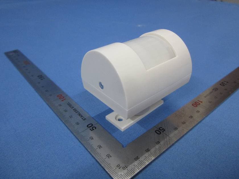
TXL3601
May 08, 2015Wireless Motion-Activated Sensor
Equipment Class
DSC - Part 15 Security/Remote Control Transmitter
TXL34080
Jan 07, 2014Transmitter for use in a wireless alert system
Equipment Class
DSC - Part 15 Security/Remote Control Transmitter