TXL34108Remote Control
Safety Technology International, Inc.
Click to zoom
Application Details
- Equipment Class
- DSR - Part 15 Remote Control/Security Device Transceiver
- Date of Grant
- Nov 24, 2010
- Application Purpose
- Original Equipment
- Date of Application
- Nov 23, 2010
- Equipment Note
- Remote Control
- Frequency Range
- 433.92000000 - 433.92000000
- Country
- United States
Documents & Files
Document Text
Text extracted from the exhibit documents filed with the FCC. Open a document above to read the original.
Users Manual
Page 1 Installation and Operation Manual STI 8 Channel Wireless Monitor TM Model: STI-34108 Thank you for purchasing this fine product. We want you to know that your satisfaction is very important to us. We suggest you take the time to read this manual carefully to get the most from your new product. HOW THE PRODUCT WORKS STI offers multiple wireless products designed to alert you of several different conditions. The STI 8 CHANNEL WIRELESS MONITOR allows you to monitor up to 8 different STI devices at a single convenient location. When placed in Enroll Mode, it allows you to select 1 of 8 different zones that will represent your STI device(s) best, and enrolls it when the monitor detects the STI device's wireless signal. The STI wireless device family uses a system that also ensures other devices that are not from STI will not get enrolled or detected. So there are no concerns about accidental enrollment, alerts or crosstalk. The STI 8 CHANNEL WIRELESS MONITOR allows you to select turning on a siren, sounding a chime, triggering a normally open or normally closed switch, or turning on an external 12 VDC output. It also allows you to choose which devices shall have latching, when selected during enrollment. The STI 8 Channels Wireless Monitor also acts as a repeater when paired with other STI 8 CHANNEL WIRELESS MONITORS to receive wireless transmissions over long distances or around disruptive terrain. Page 2 BEFORE YOU START Refer to these drawings to become familiar with all the parts. Page 3 Switch, Indicator and Plug Descriptions: DIP Switches (1-8) - The following information is written on the receiver. Below is a description of the DIP switch usage. 1-MIRROR MASTER OFF/ON 2-NORMAL/ENROLL 3-AUTO RESTORE/LATCH 4-SIREN TIME/MIRROR# 5-SIREN TIME/MIRROR# 6-CHIME OFF/ON 7-NORMAL/DELETE 8-MIRROR SLAVE OFF/ON SIREN SW4 SW5 TIME MIRROR# OFF OFF DISABLED 1 ON OFF 30 SEC 2 OFF ON 180 SEC 3 ON ON ON CONT 4 Page 4 Push Button - Selects zone to enroll or delete, acknowledge latched alert (resets LED to GREEN), silences alarm. LEDs (1-8) - Each enrolled sensor or mirrored receiver has an LED that indicates the current state of that zone from the top LED (Zone 1) down to the bottom LED (Zone 8). The Zone states are: l LED GREEN = Zone Normal l LED RED = Zone Alarm l LED RED (flashing) = Zone Latched (zone was in alarm and returned to normal) l LED AMBER = Sensor Trouble (battery or sensor tamper trouble detected) l LED off = Zone not enrolled Sounder - Audio feedback for alarm, chime, zone enrollment and deletion. Adapter Plug Input - Input connector 12VDC, 500mA, center positive adapter (provided). Triggered Output Plug - 12VDC output connector. Activates with 12VDC, 75mA max. for 3 seconds when zone is triggered. Designed for use with STI Lamp Controller (STI-30104 sold separately). Terminal Descriptions: Form C Switch Outputs (Dry Contacts) N.O. - Normally open circuit to COM terminal. Closed to COM when alarm is triggered. COM - Common return between N.O. or N.C. N.C. - Normally closed circuit to COM terminal. Open to COM when alarm is triggered. 12VDC (500mA) Input +12VDC - Positive voltage input. Power Input circuit rated to 500mA current. -12VDC - Negative voltage input. 12VDC Output (300mA max.) +12VDC - Positive output voltage. 300mA maximum output current. -12VDC - Negative output voltage. A continuous 12VDC output is produced only while sounder is activated. Page 5 INSTALLATION GUIDE Surface Installation: 1. Ensure mounting screws are removed. 2. Insert rubber feet (provided) into holes on bottom cover 3. Route wires under the product. If using for the first time or for enrollment adjustments, follow Zone Enrolling instructions. Otherwise, STI 8 CHANNEL WIRELESS MONITOR should be fully functional. Wall Mounted Installation: 1. Ensure rubber feet are removed 2. Remove front cover screw 3. Remove cover (be careful not to lose push button) 4. Mark mounting holes on wall using bottom cover as template 5. Drill holes with 3/16" drill bit 6. Insert wall anchors (provided) 7. Insert power cord and wires and route on the back 8. Insert mounting screws (provided) into plastic washers (provided) 9. Insert mounting screws into PCB holes through back of cover 10. Insert mounting screws into wall anchors and tighten 11. Press fit push button onto the push button switch on the circuit board 12. Insert top cover tabs into bottom cover slots 13. Carefully, close top cover ensuring the push button inserts into cover hole and antennas rest in the side cover groves. 14. Insert front cover screw and tighten 15. Plug in AC adaptor If using for the first time or for enrollment adjustments, follow Zone Enrolling instructions. Otherwise, STI 8 CHANNEL WIRELESS MONITOR should be fully functional. Page 6 OPERATING INSTRUCTIONS Zone Enrolling: The STI 8 Channel Receiver is designed to receive ONLY wireless signals from products in the STI Wireless Family of Products (See Back of the Installation Instructions). The STI 8 Channel Receiver allows you to enroll up to 8 devices into zones 1 thru 8 of the receiver. The STI 8 Channel Receiver will enroll from the different sensors directly or by enrolling other mirrored STI 8 Channel Receivers. The STI 8 Channel Receiver also enrolls up to 2 keyfobs. When ENROLL mode is enabled DIP SW2 (ON), the LEDs for any currently enrolled zones will turn RED to indicate that these zones are not available. The LED will flash GREEN to indicate the zone to be enrolled. Press the push button to change to a different zone to be enrolled. The next available zone will have the flashing GREEN LED. The receiver will not allow enrollment in an occupied zone. The receiver will not enter ENROLL mode while it is in DELETE mode, i.e. DIP SW7 (ON). Zone Latching: A zone will have "latching" when DIP SW3 (ON) at the time of enrollment. "Latching" shows a zone alert was triggered and the alert has been cleared since then. When a zone is in the "latched" status, the zone LED will flash RED. For examp…
Text truncated - open the document above for the full version.
Cover Letter(s)
Authority to Act as Agent November 8, 2010 American Telecommunication Certification Body, Inc. 6731 Whittier Avenue Suite C110 McLean, VA 22101 To Whom It May Concern: ______Rob Hendrickson at Resolution Engineering, Inc.______ is authorized to act on our behalf, until otherwise notified, for applications to American Telecommunication Certification Body, Inc. (ATCB). We certify that we are not subject to denial of federal benefits, that includes FCC benefits, pursuant to Section 5301 of the Anti-Drug Abuse Act of 1988, 21 U.S.C. 862. Further, no party, as defined in 47 CFR 1.2002 (b), to the application is subject to denial of federal benefits, that includes FCC benefits. Thank you, Agency Agreement Expiration Date: November 8, 2011 By: __________ John Taylor (Signature) (Print Name) Title: Executive Vice President On behalf of: Safety Technology International, Inc. Telephone: 248-673-9898
Cover Letter(s)
Request for Confidentiality November 8, 2010 Subject: Confidentiality Request for FCC ID: ______TXL-34108_____ Pursuant to FCC 47 CRF 0.457(d) and 0.459 and IC RSP-100, Section 10, the applicant requests that a part of the subject FCC application be held confidential. Type of Confidentiality Requested Exhibit Short Term Permanent Block Diagrams Short Term External Photos Short Term Permanent* 1 Internal Photos Short Term Permanent Operation Description/Theory of Operation Short Term Permanent Parts List & Placement/BOM Short Term Permanent Tune-Up Procedure Short Term Permanent Schematics Short Term Test Setup Photos Short Term Permanent* User’s Manual *Note: Safety Technology International, Inc. has spent substantial effort in developing this product and it is one of the first of its kind in industry. Having the subject information easily available to "competition" would negate the advantage they have achieved by developing this product. Not protecting the details of the design will result in financial hardship. Permanent Confidentiality: The applicant requests the exhibits listed above as permanently confidential be permanently withheld from public review due to materials that contain trade secrets and proprietary information not customarily released to the public. Short-Term Confidentiality: The applicant requests the exhibits selected above as short term confidential be withheld from public view for a period of Not Applicable days from the date of the Grant of Equipment Authorization and prior to marketing. This is to avoid premature release of sensitive information prior to marketing or release of the product to the public. Applicant is also aware that they are responsible to notify ATCB in the event information regarding the product or the product is made available to the public. ATCB will then release the documents listed above for public disclosure pursuant to FCC Public Notice DA 04-1705. Sincerely, By: _ _/Executive Vice President_ John Taylor (Signature/Title 2 ) (Print name) 1 - The asterisked items (*) require further justification before permanent confidentiality will be allowed. These also currently require review by the FCC under their Permit-But-Ask policy before the grant is issued and can delay completion of an application. Further justification should be added to the note above. One such example for a potted device would be: “The EUT is FULLY potted using a non-removable epoxy based material. Removal of potting material causes irreparable damage to internal circuitry. See photographs exhibits that outline the device before and after potting.” 2 - Must be signed by applicant contact given for applicant on the FCC site, or by the authorized agent if an appropriate authorized agent letter has been provided. Letters should be placed on appropriate letterhead.
Test Report
Safety Technology International, Inc. FCC ID: TXL34108 Certification Test Report 2010-11-16 Contents 1. Introduction ................................................................................................................................................................. 3 2. Statement of Compliance ............................................................................................................................................ 3 2.1. FCC Part 2 §2.907 ................................................................................................................................................ 3 2.2. FCC Part 2 §2.911 ................................................................................................................................................ 3 2.3. FCC Part 2 §2.913 ................................................................................................................................................ 3 2.4. FCC Part 2 §2.915 ................................................................................................................................................ 3 2.5. FCC Part 2 §2.925 ................................................................................................................................................ 4 2.6. FCC Part 2 §2.943, 2.945 .................................................................................................................................... 4 2.7. FCC Part 2 §2.947 ................................................................................................................................................ 4 2.8. FCC Part 2 §2.948 ................................................................................................................................................ 4 2.9. FCC Part 2 §2.1033 .............................................................................................................................................. 5 3. Discussion of Laboratory Measurements and Rules Compliance ............................................................................... 6 3.1. FCC Part 15 §15.231(a)(1) .................................................................................................................................. 6 3.2. FCC Part 15 §15.231(a)(2) .................................................................................................................................. 6 3.3. FCC Part 15 §15.231(a)(3) .................................................................................................................................. 6 3.4. FCC Part 15 §15.231(a)(4) .................................................................................................................................. 6 3.5. FCC Part 15 §15.231(a)(5) .................................................................................................................................. 6 3.6. FCC Part 15 §15.231(b) ....................................................................................................................................... 6 3.6.1. Raw Field Strength Limits ............................................................................................................................ 6 3.6.2. Duty Cycle Correction Factor and Resulting Limits ..................................................................................... 7 3.6.3. Measured Radiated Field Strength Data ....................................................................................................... 7 3.7. FCC Part 15 §15.231(c) ....................................................................................................................................... 7 1.Introduction The 34108 is an RF transceiver for use in a wireless alert system. See attachment “Operational Description.pdf” for a more detailed description. Certification is requested under FCC Rules, Part 15, Subpart C, Paragraph 15.231. 2.Statement of Compliance Specific sections of FCC Rules Part 2 that require information or listing are given below. 2.1.FCC Part 2 §2.907 This is an application for certification of original equipment 2.2.FCC Part 2 §2.911 a)This application has been filed electronically using form 731. b) All required information has been supplied in this application and its attachments. c)This applicant has signed the application electronically. d) The technical test data has been signed by the agency performing the testing. e)Signature supplied in appropriate block on form 731. f)Processing fee has been paid by credit card. g) Signatures have been supplied electronically. 2.3.FCC Part 2 §2.913 a)This application has been filed electronically. b) Appropriate fees have been filed electronically. c)Equipment samples shall be supplied as requested. 2.4.FCC Part 2 §2.915 We are requesting a grant of certification. This application shows compliance with the technical standards. 2.5.FCC Part 2 §2.925 A label shall be affixed to each piece of equipment, showing the FCC identifier. The label shall read “FCC ID: TXL34108”. See exhibit “Label.pdf” for photographs showing the label and location on the device. External and internal photos are provided in exhibits “External Photos.pdf” and “Internal Photos.pdf”. 2.6.FCC Part 2 §2.943, 2.945 Sample production equipment shall be submitted to the FCC upon request. 2.7.FCC Part 2 §2.947 a)Measurement procedure follows ANSI C63.4 version 2003 b) A description of utilized test equipment is contained in attached “Radiated Data.pdf”. 2.8.FCC Part 2 §2.948 Radiated measurements were taken at the following FCC-approved facility: Rhein Tech Laboratories, Inc. 360 Herndon Pkwy, Suite 1400 Herndon, VA 20170 Contact: Rick McMurray Phone: 703-689-0368 See exhibit “Test Setup Photo.pdf” for a photo of the test site. 2.9.FCC Part 2 §2.1033 a. Form 731 has been filed electronically. b. The technical report, along with its exhibits, contains the information as follows: 1. Full name and maili…
Text truncated - open the document above for the full version.
Test Report
360 Herndon Parkway, Suite 1400 Herndon, VA 20170 Tel: 703-689-0368 Fax: 703-689-2056 Page 1 of 6 Engineering and Testing for EMC and Safety Compliance Accredited under A2LA Testing Certificate # 2653.01 Radiated Test Data for Model: STI Monitor 433.9 MHz for Resolution Engineering RTL Project Number 2010023 Test Engineer: Jon Wilson 360 Herndon Parkway, Suite 1400 Herndon, VA 20170 Tel: 703-689-0368 Fax: 703-689-2056 Page 2 of 6 Mains Conducted Result: Pass Rhein Tech Laboratories, Inc. EN 55022, Class B Phase Line 100.0K1.0M10.0M100.0M Frequency MHz 0 10.0 20.0 30.0 40.0 50.0 60.0 70.0 80.0 90.0 100.0 Amplitude dBuV Project #: 2010023 STI Monitor 433.9 MHz01:20:17 PM, Sunday, March 21, 2010 C:\Tile4\RTL Conducted Emissions\SA3 SR2 RTL_CE_CISPR_B.TIL Operator: Jon W ilson CISPRB_QP CISPRB_AV C_Line_1 Line_1_qp Final_L1_Avg Rhein Tech Laboratories, Inc. EN 55022, Class B Neutral Line 100.0K1.0M10.0M100.0M Frequency MHz 0 10.0 20.0 30.0 40.0 50.0 60.0 70.0 80.0 90.0 100.0 Amplitude dBuV Project #: 2010023 STI Monitor 433.9 MHz01:22:17 PM, Sunday, March 21, 2010 C:\Tile4\RTL Conducted Emissions\SA3 SR2 RTL_CE_CISPR_B.TIL Operator: Jon W ilson CISPR B Avg CISPR B QP Neutral Scan Line_2_qp Final_L2_Avg 360 Herndon Parkway, Suite 1400 Herndon, VA 20170 Tel: 703-689-0368 Fax: 703-689-2056 Page 3 of 6 Radiated Test Data - OATS 1 Test Date: March 21, 2010 Work Order: 2010023 Customer Reference: BC 019406 Model: STI Monitor Mode: STI Monitor 433.9 MHz Name: Jon Wilson Limit/Distance: FCC B/3m Emission Frequency (MHz) Test Detector Analyzer Reading (dBuV) Site Correction Factor (dB/m) Emission Level (dBuV/m) Limit (dBuV/m) Margin (dB) Pass/ Fail 433.933 Pk 61.7 32.9 94.6 100.8 -6.2 Pass 867.865 Pk 65.3 0.7 66.0 80.8 -14.8 Pass 1301.799 Pk 40.0 8.4 48.4 80.8 -32.4 Pass 1735.692 Pk 43.6 13.1 56.7 80.8 -24.1 Pass 2,169.70 Pk 37.5 9.0 46.5 80.8 -34.3 Pass 2,603.65 Pk 40.4 10.4 50.8 80.8 -30.0 Pass 3,037.59 Pk 48.6 8.8 57.4 80.8 -23.4 Pass 3,471.53 Pk 41.0 9.0 50.0 80.8 -30.8 Pass 3,905.47 Pk 36.8 10.9 47.7 80.8 -33.1 Pass 4,339.42 Pk 35.9 14.9 50.8 80.8 -30.0 Pass 360 Herndon Parkway, Suite 1400 Herndon, VA 20170 Tel: 703-689-0368 Fax: 703-689-2056 Page 4 of 6 360 Herndon Parkway, Suite 1400 Herndon, VA 20170 Tel: 703-689-0368 Fax: 703-689-2056 Page 5 of 6 360 Herndon Parkway, Suite 1400 Herndon, VA 20170 Tel: 703-689-0368 Fax: 703-689-2056 Page 6 of 6 Radiated Emissions Test Equipment Part Manufacturer Model Serial Number Barcode Cal Due Date Amplifier (20 MHz-2 GHz) Rhein Tech Laboratories, Inc. PR-1040 900905 900905 4/10/2010 Bilog Periodic Antenna (25 MHz-2 GHz) Schaffner Chase CBL6112 2099 900791 12/12/2010 EMI Receiver RF Section (9 KHz-6.5 GHz) Hewlett Packard 85462A 3325A00159 900913 6/8/2010 RF Filter Section (100 KHz-6.5 GHz) Hewlett Packard 85460A 3330A00107 900914 6/8/2010 Spectrum Analyzer Hewlett Packard 8596EM 3826A00144 901215 11/23/2010 Amplifier (1 GHz – 26.4 GHz) Hewlett Packard 8449B OPT H02 3008A00505 900932 2/22/2011 Horn Antenna, 2.0-4.0 GHz EMCO 3161-02 9804-1044 900772 6/13/2010 Horn Antenna, 4.0-8.2 GHz EMCO 3161-03 9508-1020 900321 6/13/2010 Emissions Testing Software Rhein Tech Laboratories, Inc. Automated Emission Tester Rev. 14.0.2 N/A N/A Conducted Emissions Test Equipment Part Type Manufacturer Model Serial Number Barcode Cal Due Date Spectrum Analyzer (100Hz-.15GHz) Hewlett Packard 8567A 2602A00160 900968 9/8/2010 Spectrum Analyzer Display Section Hewlett Packard 85662A 2542A11239 900970 9/8/2010 Quasi-Peak Adapter Hewlett Packard 85650A 2521A00743 900339 9/8/2010 Filter Solar 8130 947306 900729 8/19/2010 16A LISN AFJ International LS16/110VAC 16010020080 901083 11/4/2010 Emissions testing software Rhein Tech Laboratories, Inc. Automated Emission Tester Rev. 14.0.2 N/A N/A Test software Quantum Change Tile! 4.0.A.8 N/A N/A
Test Setup Photos
360 Herndon Parkway, Suite 1400 Herndon, VA 20170 Tel: 703-689-0368 Fax: 703-689-2056
Contact Information
Applicant
John F. Taylor(Executive Vice President)
Technical Contact
Resolution Engineering Inc.Rob Hendrickson
[email protected]651 269 2172
226 Locust Street · Hudson, Wisconsin · United States
Test Firm
Rhein Tech Laboratories, Inc.Richard McMurray
Technical Specifications
| # | Rule Parts | Frequency Range | Power Output |
|---|---|---|---|
| 1 | 15.231 | 433.92 MHz - 433.92 MHz | - |
Other Applications from Safety Technology International, Inc.
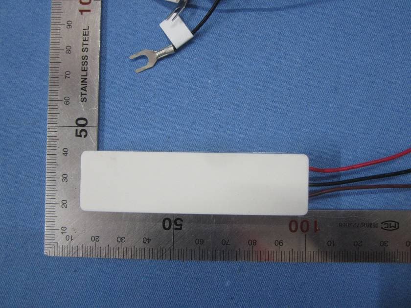
TXL3331
Jun 20, 2015Wireless Doorbell Extender
Equipment Class
DSC - Part 15 Security/Remote Control Transmitter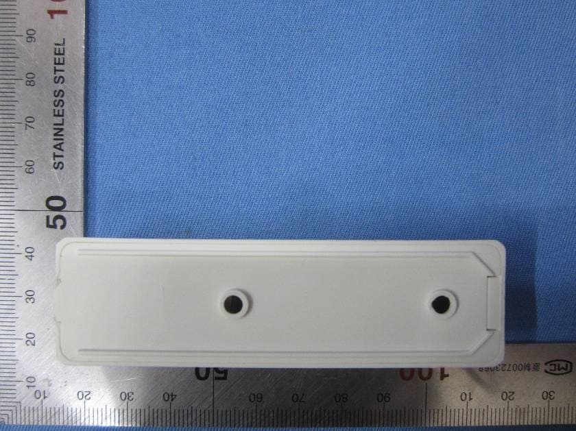
TXL3301
May 08, 2015Wireless Doorbell Chime Sensor
Equipment Class
DSC - Part 15 Security/Remote Control Transmitter
TXL3551
May 08, 2015Wireless Entry Alert Sensor
Equipment Class
DSC - Part 15 Security/Remote Control Transmitter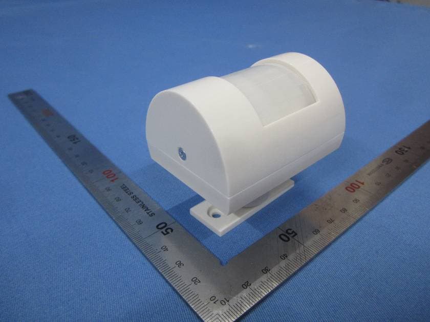
TXL3601
May 08, 2015Wireless Motion-Activated Sensor
Equipment Class
DSC - Part 15 Security/Remote Control Transmitter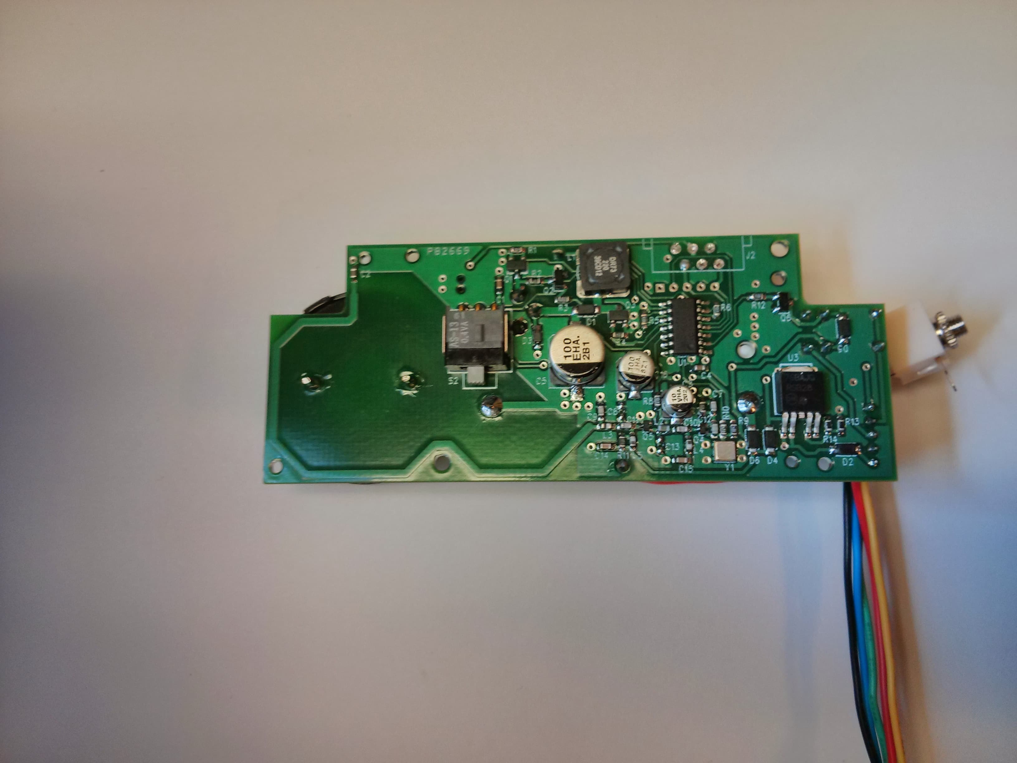
TXL34080
Jan 07, 2014Transmitter for use in a wireless alert system
Equipment Class
DSC - Part 15 Security/Remote Control Transmitter