TXL34401UNIVERSAL TRANSMITTER
Safety Technology International, Inc.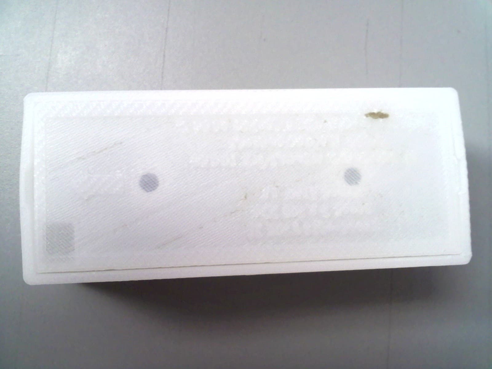
Click to zoom
Application Details
- Equipment Class
- DSC - Part 15 Security/Remote Control Transmitter
- Date of Grant
- Dec 07, 2010
- Application Purpose
- Original Equipment
- Date of Application
- Dec 07, 2010
- Equipment Note
- UNIVERSAL TRANSMITTER
- Frequency Range
- 433.92000000 - 433.92000000
- Country
- United States
Documents & Files

Document Text
Text extracted from the exhibit documents filed with the FCC. Open a document above to read the original.
Users Manual
Installation and Operation Manual STI Universal Sensor Model: STI-34401 Thank you for purchasing this fine product. We want you to know that your satisfaction is very important to us. We suggest you take the time to read this manual carefully to get the most from your new product. HOW THE PRODUCT WORKS The STI Universal Sensor has a reed switch, tilt switch and terminals for an external switch input read by STI receivers as the 3 different “Sensor Configuration" transmissions. Jumper wires must be configured for the appropriate sensor application (door sensor, mailbox alert, garage door sentry, etc). Sensor Configurations (MAGNETIC, TILT, EXTERNAL): The Magnetic Sensor, Tilt Sensor and External Terminals each have their own Sensor Configuration, and each STI Universal Sensor has its own ID number to ensure there is no duplication of wireless signals to an STI receiver. To allow multiple Universal Sensors with the same Sensor Configuration, STI receivers interpret each Sensor Configuration and ID number pair as a separate and unique input signal. The U-Sensor transmits only a single Sensor Configuration (MAGNETIC, TILT, or EXTERNAL) depending upon how the jumper wires are configured. The sensor will not react to other device changes if the jumper configuration is not set. For example, the magnetic sensor open and close changes will not be transmitted in the wireless message if the sensor is configured as a TILT SENSOR type. Jumper Configurations: Installation and Operation Manual STI Universal Sensor Model: STI-34401 U-Sensor Setup: 1. Open device using a flat head screwdriver in the slot under the case. 2. Configure the jumpers for the desired application. (See Jumper Configuration) 3. Insert 3V lithium 123A size battery in the proper orientation. 4. Program the STI Universal Sensor into the STI receiver. NOTE: Please refer to the STI receiver installation instructions for this. 5. Place the Tamper Switch Spring onto tamper switch after jumpers have been configured and battery has been inserted. Tamper alert is triggered when spring releases. Intended to identify when case is opened/broken/ajar. 6. Snap base into lid. Ensure that Tamper Switch Spring is within the Spring Locator circle on the lid and compresses when the lid is snapped shut. Mounting: OPTION 1: Mount with double sided tape (provided) to the back of the case. OPTION 2: Remove the circuit board from the case bottom. Drill 1/8” holes through the case knock outs and in the mounting locations, and apply the screws (provided). For added protection, cover metal screw heads on the inside of the case bottom with electrical tape to isolate the circuit board. Replace the circuit board in the case bottom. When using the Magnetic Sensor, the bottom case may be inserted into the top case in reverse depending on which direction the Magnetic Sensor should face. When using the Tilt Sensor, the arrow on the bottom should point straight up in the non-triggered state. When using the External Terminals, remove the case knock out in the corner of the case bottom to insert sensor wires. (Note: Do not use outdoors when using External Terminals) Installation and Operation Manual STI Universal Sensor Model: STI-34401 Operation: Magnetic Sensor: • Alert Signal – Magnet is over 1-1/2” from the “ ►“ shape. (typically) • Restore Signal – Magnet is brought within 1-1/4” from the “►“ shape. (typically) Tilt Sensor: • Alert Signal – Sensor is tilted more than 45° from vertical. • Restore Signal – Sensor is tilted less than 45° from vertical. Ext. Sensor Input: • Alert Signal – Terminals must first have a short circuit then an open circuit any time afterward will trigger an Alert signal. • Restore Signal – Terminals have a short circuit. NOTE: An Alert or Restore signal must be triggered for an STI receiver to acknowledge any one of the 3 Sensor Configurations. Sensor Trouble Detection: If the STI Universal Sensor has a Low Battery or triggered Tamper Switch, the sensor will send a trouble signal to the receiver. If there is a Loss of Communication with the receiver, the receiver also will indicate a trouble condition with that device. IMPORTANT NOTICE: Changes or modifications not expressly approved by the manufacturer could void the user's authority to operate this equipment. This device complies with Part 15 of the FCC rules. Operation is subject to the following two conditions: 1) This device may not cause harmful interference. 2) This device must accept any interference that may be received, including interference that may cause undesired operation. Model: 34401 FCC ID: TXL34401 IC: 6550A-34401 This product meets the applicable Industry Canada technical specifications. Le présent materiel est conforme aux specifications techniques applicables d’Industrie Canada.
Block Diagram
MODEL: 34401 FCC ID: TXL34401 IC: 6335A-34401 BLOCK DIAGRAM
External Photos
APPLICANT: SAFETY TECHNOLOGY INTERNATIONAL INC. FCC ID: TXL34401
ID Label/Location Info
1 1 2 2 3 3 4 4 AA BB CC DD SHEET 1 OF 1 DRAWN CHECKED QA MFG APPROVED jstrong 9/15/2010 DWG NO BasePlate-5 TITLE SIZE C SCALE REV
Internal Photos
APPLICANT: SAFETY TECHNOLOGY INTERNATIONAL INC. FCC ID: TXL34401
Operational Description
MODEL: 34401 FCC ID: TXL34401 IC: 6335A-34401 OPERATIONAL DESCRIPTION The 34401 is a small sensor for use in a wireless alert system. It is battery powered using a 3V CR123A size battery. It measures approximately 1½ x 3¼ x 1 inches and weighs approximately 2 ounces. It transmits packets for the purpose of alerting a user when a mailbox door, a standard door or window have been opened using either an on board magnetic reed sensor, an on board tilt sensor, or an off board device wired to two on board terminals. A microcontroller monitors the input of only one of the previously mentioned sensors configured for use by shorted or opened jumper circuits together with the associated circuitry. When a valid state change of the chosen sensor has been detected, the microcontroller transmits eight data packets. In the absence of external activations, a group of three supervision transmissions are sent once per hour. The transmitter circuit consists of a 433.92MHz SAW resonator, an oscillator transistor, an amplifier transistor, and associated passives. The amplifier stage is turned on and off to modulate the carrier. A bar antenna radiates the RF signal. The transmitted packet is ASK modulated and has an on-time of 9.6ms. Precautions are taken in the firmware to ensure that there is at least 100ms between packets.
Schematics
05-06-10 A 30401 Universal Transmitter STI <Drawn By> <Checked By> <QC By> <Released By> <Checked Date><QC Date><Release Date> <Code> B <Scale> 1 1 REV: SIZE: CODE: DRAWN: DATED: DATED: CHECKED:QUALITY CONTROL: DATED: DATED: RELEASED: COMPANY:TITLE: DRAWING NO: SHEET: OF SCALE: REVISION RECORD APPROVED: ECO NO: ABD DATE: 1 2 3 4 5 6 DCAB C LTR Q1 NE85619 NE85619-T1-A S1 SPST A1 2.75" BAR ANTENNA R1 750 Ohms R2 750 Ohms R310K C1DNS C2 0.1uF C3 3.3pF C43.3pF C5 0.1uF L1 82nH L282nH L3 82nH S2 SWITCH-REED-TH-HASCO-HCC213 REED SWITCH 1 GND 2 +3V B1 CONN-BATT-HOLDER-KEYSTONE-1029 L4 82nH C61.5pF Q2NE58219 C78.2pFC88.2pF R4220 Ohms R5 47K 1 VDD 3 RA4/T1G/OSC2/CLKOUT 12 RA1/C1IN-/VREF/ICSPCLK 7 RC3 11 RA2/TOCKL/INT/C1OUT 4 RA3/MCLR/VPP 2 RA5/T1CKL/OSC1/CLKIN 14 VSS 9 RC1/C2IN- 8 RC2 6 RC4/C2OUT 10 RC0/C2IN+ 5 RC5 13 RA0/C1IN+/ICSPDAT/ULPWU U1 PIC16F636-I/SL 1 G 2 IN 3 G 6 G 5 OUT 4 G Y1 433.92MHZ SAW RES C90.1uF TP1 TP2 TP3 TP4 TP5 1 X1 not a part 1 X2 not a part 1 X3 not a part C10 DNS R6 330 Ohms R7 330 Ohms D110V D2 BAT54HT1G R8 DNS 12 J1 1 2 S3 R9100K R10100K C11 0.1uF R11 750 Ohms R12 100K 1 2 JP1 WIREJUMPER 1 2 JP2 WIREJUMPER 1 2 JP3 1 1 VDD 2 PGD 3 PGC 4 GND 5 MCLR X4 R13 DNS R14100K TAMP TAMP TILT TILT PGC/EXTERNAL PGD/REED PGC/EXTERNAL PGD/REED GND VBATMCLR PGD/REED PGC/EXTERNAL MCLR MCLR VBAT PGD/REEDPGC/EXTERNAL TX_DATA PULL PULL VBAT TX_EN TX_DATA TX_EN VBAT VBAT VBAT TX_DATA
Test Report
FCC PART 15.231 AND RSS-210 TEST REPORT LOW POWER UNLICENSED TRANSMITTER Applicant SAFETY TECHNOLOGY INTERNATIONAL, INC. Address 2306 AIRPORT ROAD WATERFORD MICHIGAN 48327-1209 USA FCC ID TXL34401 IC 6335A-314401 MODEL 314401 Product Description UNIVERSAL TRANSMITTER Date Sample Received 7/22/2010 Date Tested 8/24/2010 Tested By Nam Nguyen Approved By Mario de Aranzeta Timco Report No. 1751AT10TestReport.doc Test Results Pass Fail THE ATTACHED REPORT SHALL NOT BE REPRODUCED EXCEPT IN FULL WITHOUT THE WRITTEN APPROVAL OF TIMCO ENGINEERING, INC. 849 NW STATE ROAD 45 NEWBERRY, FL 32669 USA PH: 888.472.2424 OR 352.472.5500 FAX: 352.472.2030 EMAIL: [email protected] HTTP://WWW.TIMCOENGR.COM Certificate # 0955-01 APPLICANT: SAFETY TECHNOLOGY INTERNATIONAL, INC. FCC ID: TXL34401 REPORT: S\SAFETY\1751AT10\1751AT10TestReport.doc Page 2 of 15 mdea 09.20.2007 TABLE OF CONTENTS GENERAL REMARKS .................................................................................................. 3 REPORT SUMMARY .................................................................................................... 4 TEST ENVIRONMENT.................................................................................................. 4 TEST SETUP ............................................................................................................... 4 DUT SPECIFICATION .................................................................................................. 5 MANUFACTURE DECLARATION OF COMPLIANCE WITH PART 15.231(A) ..................... 6 TEST EQUIPMENT LIST .............................................................................................. 7 TEST PROCEDURES ................................................................................................... 8 RADIATION INTERFERENCE ....................................................................................... 9 CALCULATION OF DUTY CYCLE ............................................................................... 13 OCCUPIED BANDWIDTH........................................................................................... 14 POWER LINE CONDUCTED INTERFERENCE ............................................................. 15 APPLICANT: SAFETY TECHNOLOGY INTERNATIONAL, INC. FCC ID: TXL34401 REPORT: S\SAFETY\1751AT10\1751AT10TestReport.doc Page 3 of 15 mdea 09.20.2007 GENERAL REMARKS The attached report shall not be reproduced except in full without the written permission of Timco Engineering Inc. Summary The device under test does: fulfill the general approval requirements as identified in this test report not fulfill the general approval requirements as identified in this test report Attestations This equipment has been tested in accordance with the standards identified in this test report. To the best of my knowledge and belief, these tests were performed using the measurement procedures described in this report. All instrumentation and accessories used to test products for compliance to the indicated standards are calibrated regularly in accordance with ISO 17025 :2005 requirements. Certificate # 0955-01 I attest that the necessary measurements were made, under my supervision, at: Timco Engineering Inc. 849 NW State Road 45 Newberry, Fl 32669 Authorized Signatory Name: Mario de Aranzeta C.E.T. Compliance Engineer/ Lab. Supervisor Date: 8/26/2010 APPLICANT: SAFETY TECHNOLOGY INTERNATIONAL, INC. FCC ID: TXL34401 REPORT: S\SAFETY\1751AT10\1751AT10TestReport.doc Page 4 of 15 mdea 09.20.2007 REPORT SUMMARY Disclaimer The test results only relate to the item tested. Applicable Rule(s) FCC Pt 15.231, Pt 15.209, Pt 15.207, ANSI C63.4: 2003, RSS-210, RSS-GEN TEST ENVIRONMENT Test Facility The test sites are located at 849 NW State Road 45 Newberry, FL 32669 USA. Test Condition: Temperature: 26ºC Relative humidity: 50% TEST SETUP Test Exercise (e.g. software description, test signal, etc.): The DUT was placed in continuous transmit mode of operation. Deviation from the standard(s) No deviation from the standard(s) Modification to the DUT: No modification was made to the DUT. Supporting Peripheral Equipment Not applicable. The device is a stand-alone remote control radio. APPLICANT: SAFETY TECHNOLOGY INTERNATIONAL, INC. FCC ID: TXL34401 REPORT: S\SAFETY\1751AT10\1751AT10TestReport.doc Page 5 of 15 mdea 09.20.2007 DUT SPECIFICATION Applicant SAFETY TECHNOLOGY INTERNATIONAL, INC. Description UNIVERSAL TRANSMITTER FCC ID TXL34401 IC 6335A-34401 MODEL 34401 Frequency Range 433.92 MHz DUT Power Source 110–120Vac/50– 60Hz DC Power Battery Operated Exclusively Test Item Prototype Pre-Production Production Type of Equipment Fixed Mobile Portable APPLICANT: SAFETY TECHNOLOGY INTERNATIONAL, INC. FCC ID: TXL34401 REPORT: S\SAFETY\1751AT10\1751AT10TestReport.doc Page 6 of 15 mdea 09.20.2007 MANUFACTURE DECLARATION OF COMPLIANCE WITH PART 15.231(A) Item Description Yes No 1 Does this device transmit a signal that is only used to control another device? x 2 Does this device send data with this control signal? x 3 Does this device send data? Data is, things like: temperature, wind direction, fluid amount, rate of flow, etc. x (discrete – nonvariable - data) 4 Does this device transmit continuously or automatically? x 5 If manually operated does this device stop transmitting within 5 seconds of releasing the button? x 6 If automatically operated does it deactivate 5 seconds after activation? x 7 Does it transmit at regular predetermined intervals? Only supervision signal 8 Does it poll or send supervisory information? x If yes does it do a system integrity check? How often? 1 per 60 min 9 Is this a fire, security or safety of life device? x If YES does the device stop transmitting after the alarm condition is satisfied? 10 Duty cycle: Maximum on-time? 9.6 ms 50% DC Provisions for 100ms between packets. 19.6% DC Per TIMCO MaxOn< 5s If YES, on-time in 100 ms? If Other, please specify here On time in 11 Modulation technique: Please specify the modulati…
Text truncated - open the document above for the full version.
Contact Information
Applicant
John F. Taylor(Executive Vice President)
Test Firm
Timco Engineering, Inc.Bruno Clavier
Technical Specifications
| # | Rule Parts | Frequency Range | Power Output |
|---|---|---|---|
| 1 | 15.231 | 433.92 MHz - 433.92 MHz | - |
Other Applications from Safety Technology International, Inc.
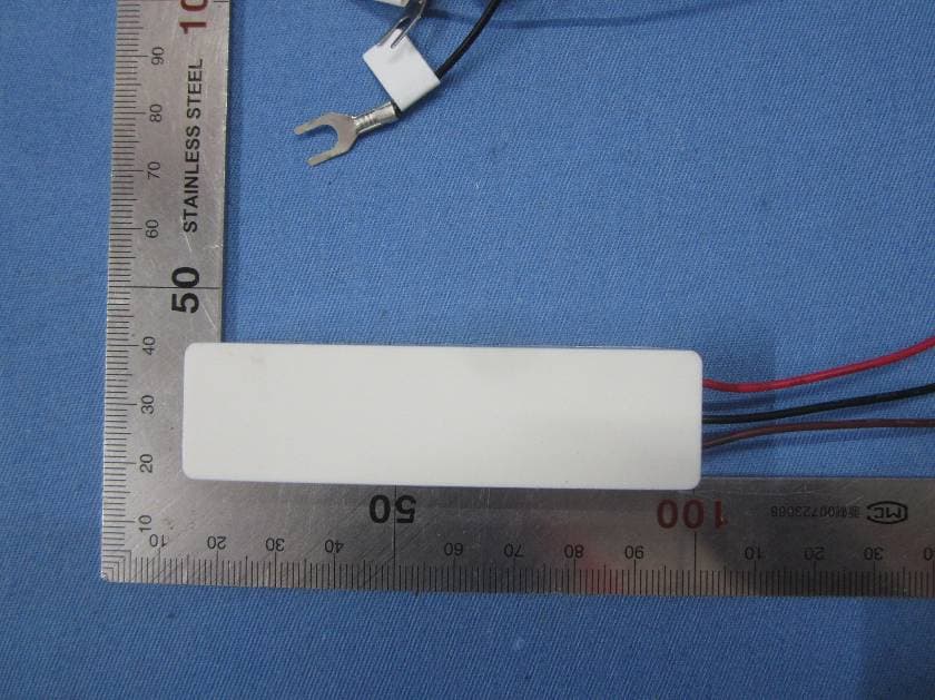
TXL3331
Jun 20, 2015Wireless Doorbell Extender
Equipment Class
DSC - Part 15 Security/Remote Control Transmitter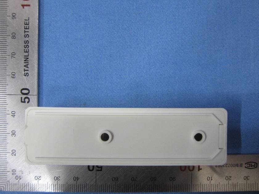
TXL3301
May 08, 2015Wireless Doorbell Chime Sensor
Equipment Class
DSC - Part 15 Security/Remote Control Transmitter
TXL3551
May 08, 2015Wireless Entry Alert Sensor
Equipment Class
DSC - Part 15 Security/Remote Control Transmitter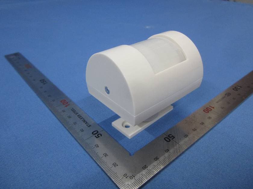
TXL3601
May 08, 2015Wireless Motion-Activated Sensor
Equipment Class
DSC - Part 15 Security/Remote Control Transmitter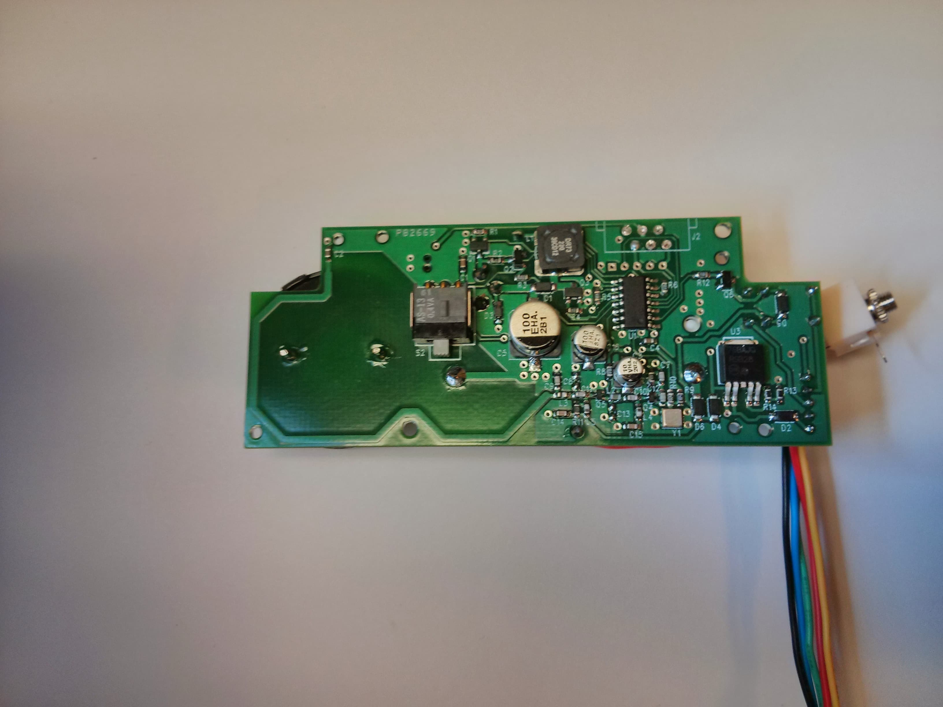
TXL34080
Jan 07, 2014Transmitter for use in a wireless alert system
Equipment Class
DSC - Part 15 Security/Remote Control Transmitter