TXL34501Transmiter for use in wireless alert system
Safety Technology International, Inc.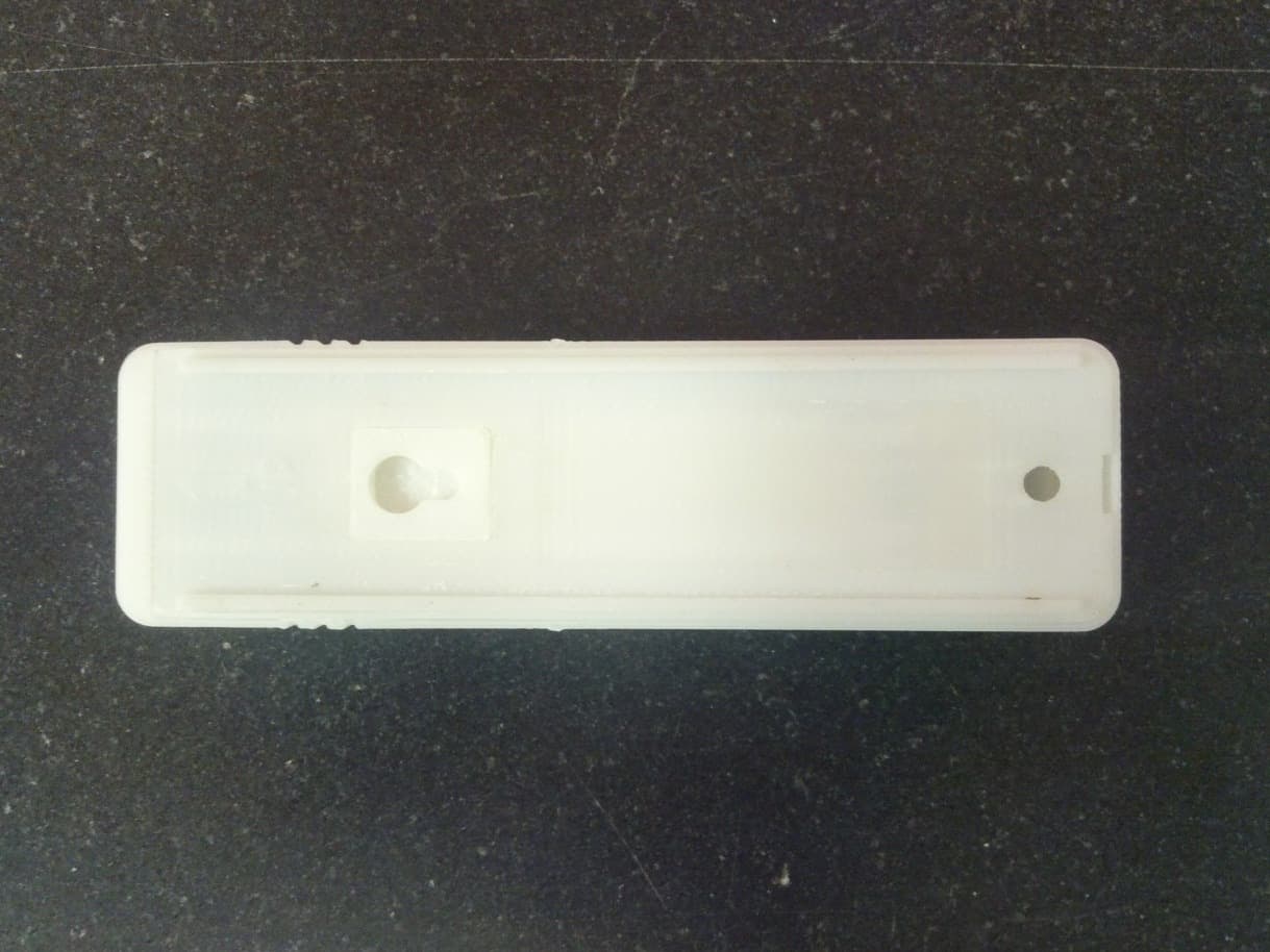
Click to zoom
Application Details
- Equipment Class
- DSC - Part 15 Security/Remote Control Transmitter
- Date of Grant
- May 06, 2012
- Application Purpose
- Original Equipment
- Date of Application
- May 06, 2012
- Equipment Note
- Transmiter for use in wireless alert system
- Frequency Range
- 433.92000000 - 433.92000000
- Country
- United States
Documents & Files
Document Text
Text extracted from the exhibit documents filed with the FCC. Open a document above to read the original.
Users Manual
Rhein Tech Laboratories, Inc. Client: STI, Inc. 360 Herndon Parkway Model: 34501 Suite 1400 Standards: FCC 15.231/IC RSS-210 Herndon, VA 20170 ID’s: TXL34501/6335A-3 4501 http://www.rheintech.com Report #: 2012026 Appendix J: Manual Please see the following pages. Installation and Operation Manual STI Wireless Pool Alert Model: STI-34501 Features and Specifications: • Water/Weather resistant for outdoor use • High output 85 dB alert siren (@ 10’) • Low battery indicator • Comes with magnet, bracket and mounting hardware • One button bypass operation • Safety feature: cover will not close if battery is not installed • Acts as a stand-alone alert or works with an STI Wireless Alert Series Receiver • CR123, 3V Lithium battery operated (included) • Material UV-Stabilized Polycarbonate • UL 2017 Residential Water Hazard Entrance Alarm Equipment (pending) Safety Technology International, Inc. “We Protect the Things that Protect You.” Thank you for purchasing the STI Wireless Pool Alert. The Pool Alert can be used to provide a high volume alert when a pool or spa area has been entered. It can be used outdoors on wood or metal gates or indoors on doorways leading directly to potentially dangerous areas. STI Wireless Pool Alert is not a substitute for supervision. Use as your “last line of defense.” Your satisfaction is important to us. Please take the time to read this manual carefully to get the most from your product. How the Product Works: STI Wireless Pool Alert is designed to detect, by way of magnetic break, a door or gate opening, will sound an 85 dB alert and transmit a 433 MHz signal to an optional STI Wireless Alert Series Receiver. Important Notes: The STI Wireless Pool Alert, when properly installed, complies with UL 2017 Residential Water-Hazard Entrance Alarm Equipment Type SM, Self-Monitored Alert System. Strict adherence to mounting height and orientation is required for code; however, there may be additional local code requirements. The alert is not allowed to have a power switch, nor is the cover allowed to be mounted to the base without a battery installed. The STI Wireless Pool Alert can provide valuable protection when used correctly; however, it cannot guarantee protection against accidents or injuries. Therefore, STI cannot be held responsible for any loss, damage or injury that may occur. It is the user’s responsibility to test and maintain the operations of the STI Wireless Pool Alert. The STI Wireless Pool Alert is water resistant, but not water proof. Do not submerge in water or allow water to enter through the locking snap. Refer to Receiver instructions for wireless programming. Operational States: Normal – all door/gates closed Pre-Alert – A series of double beeps 7 seconds before going into “Alert.” If door/gate is opened without pushing “Bypass” button, unit enters “Pre-Alert” state immediately. Bypass – press button before opening door/gate for a 15 second walk through with no alert sound. Button can be pushed at any time to reset 15 second timer. Unit will go into “Alert” unless entry is closed. Alert – full alert for opened door/gate. Red LED and 85 dB siren are continuous until the battery drains or button pressed. Press button during “Alert” to initiate “Bypass.” During “Alert”, if the door/gate is closed, siren will sound for 30 seconds, then return to normal state. Low Battery indication – at Pool Alert – 1 short beep every minute Optional receiver also has a low battery indication. See receiver instructions for information. Operating Instructions: Test and Program 1. Before mounting remove cover (Fig. 1). 2. Place magnet next to magnetic switch (location shown Fig. 4) then remove the Pink Mylar battery tab. Green LED flashes 1 time every 30 seconds (Normal State). 3. Move magnet away from magnetic switch. Pool Alert should make a series of double beeps and red LED flashes for approximately 7 seconds (Pre-Alert State), then alarm sounds and red LED is solid (Alert State). 1.5 in. (38mm) 1.26 in. (32mm) 5.15 in. (131mm) MAGNET MAGNET MOUNTING CENTER LOCATOR BYPASS SWITCH 5.2 in. (131mm) 1.3 in. (32mm) 1.5 in. (38mm) MAX 3/4 in. (19mm) (FOR INDOOR MOUNTING ONLY) WHEN MOUNTING HORIZONTALLY, SNAP COVER RELEASE MUST BE TO THE RIGHT. WHEN MOUNTING VERTICAL, SNAP COVER RELEASE MUST BE AT BOTTOM. SNAP COVER RELEASE SNAP COVER RELEASE SNAP COVER RELEASE REMOVING COVER - USING A SMALL FLAT SCREWDRIVER, PLACE SCREWDRIVER TIP ONTO SNAP COVER RELEASE AND PUSH IN GENTLY WHILE LIFTING COVER AT THE SAME TIME. STEEL POST ZIP TIE (NOT PROVIDED) MOUNTING BRACKET TEAR DROP STEM PINK MYLAR TAB #6-32 x 3/8 SCREW (1) PROVIDED POOL ALERT BASE MOUNTING BRACKET MUST BE MINIMUM 57 INCHES FROM GROUND POOL ALERT BASE POOL ALERT COVER SOUNDER PINK MYLAR TAB #6 x 1 in. SCREW (2) PROVIDED ANCHOR (2) PROVIDIED IF USING ANCHORS, DRILL 3/16 in. DIA. HOLES IF USING SCREWS ONLY, DRILL 7/64 in. DIA. HOLES DOOR JAM /GATE POST MAGNETIC SWITCH 57 in. MINIMUM MOUNTING HEIGHT FROM THRESHOLD POOL ALERT BASE A FIGURE 4 FIGURE 3 FIGURE 2 FIGURE 1 FIGURE 5 FIGURE 6 CR123 BATTERY 1.57 in. (40mm) DRILL 3/32” 4. Press Button - Pool Alert is silent (Bypass State) for approximately 8 seconds, then enters “Pre-Alert State.” 5. Press Button - Pool Alert is silent. 6. Move magnet near magnetic switch (Normal State). 7. If using wireless transmitter, refer to receiver instructions for programming. FIG. 1 1.5 in. (38mm) 1.26 in. (32mm) 5.15 in. (131mm) MAGNET MAGNET MOUNTING CENTER LOCATOR BYPASS SWITCH 5.2 in. (131mm) 1.3 in. (32mm) 1.5 in. (38mm) MAX 3/4 in. (19mm) (FOR INDOOR MOUNTING ONLY) WHEN MOUNTING HORIZONTALLY, SNAP COVER RELEASE MUST BE TO THE RIGHT. WHEN MOUNTING VERTICAL, SNAP COVER RELEASE MUST BE AT BOTTOM. SNAP COVER RELEASE SNAP COVER RELEASE SNAP COVER RELEASE REMOVING COVER - USING A SMALL FLAT SCREWDRIVER, PLACE SCREWDRIVER TIP ONTO SNAP COVER RELEASE AND PUSH IN GENTLY WHILE LIFTING COVER AT THE SAME TIME. STEEL POST ZIP TIE (NOT PROVIDED) MOUNTING BRACKET TEAR DROP STEM PINK MYLAR TAB #6-32 …
Text truncated - open the document above for the full version.
Cover Letter(s)
Rhein Tech Laboratories, Inc. Client: STI, Inc. 360 Herndon Parkway Model: 34501 Suite 1400 Standards: FCC 15.231/IC RSS-210 Herndon, VA 20170 ID’s: TXL34501/6335A-3 4501 http://www.rheintech.com Report #: 2012026 Appendix A: FCC/TCB Agency Authorization Letter Please refer to the following page. iafety lechnology Intemational, Inc. 2306 Akport noid, W.terford, H {832t U.Sl. Fhoa€: ?tl8-673-9E98. SAI:118-673-1246. WGb: www.rtFu6..(ofl!. E-ffr{: lnfu@rtl-usr,ce{B Authoritv to Act as Aqent Date Mar 12, 2012 American Certification Body, Inc. 6731 Whittier Avenue Suite C110 McLean, YA 22101 To Whom lt May Concern: Rhein Tech Laboratories, Inc. is authorized to act on our behalf, until otherwise notified, for applications to American Certification Body, Inc. (ACB). We certify that we are not subject to denial of federal benefits, that includes FCC benefits, pursuant to Section 5301 of the Anti-Drug Abuse Act of 1988, 21 U.S.C. 862. Further, no party, as defined in 47 CFR 1.2002 (b), to the application is subject to denial of federal benefits, that includes FCC benefits. Thank you, Agency Agreement Expiration Date: Feb 28,2013 (Typically 8- 12 months) By: Title: On behalt of: Safetv Technoloqv International. lnc. Telephone: (Company Name) 248€73-9898 John Taylor (Print name) Executive Vice President
Cover Letter(s)
Rhein Tech Laboratories, Inc. Client: STI, Inc. 360 Herndon Parkway Model: 34501 Suite 1400 Standards: FCC 15.231/IC RSS-210 Herndon, VA 20170 ID’s: TXL34501/6335A-3 4501 http://www.rheintech.com Report #: 2012026 Appendix B: FCC Confidentiality Request Letter Please refer to the following page. Safety Technology International, lRc. 1306 Airpod no4 ffitcrtord, H tttZT USr. Phone 2S-673-989E . f;AX: 2{S-6t3"12{6. mh wws$c..wt. E-f[rd: ffi{p$F{6|.€o6l Date Mar. 12, 2012 American Certification Body, Inc. 6731 Whittier Avenue Suite C110 Mclean, VA 22101 To Whom lt May Concern: The following information is to be held confidential pursuant to FCC 47 CFR S0.457(d) and 50.459, because the information provided contains trade secrets and is proprietary. lf made public, the information might be used to the disadvantage of the applicant in the market place. . Schematics o Technical Product Descriotion . Block Diagram Sincerely, Exec utiv e vice P reside nt
External Photos
Rhein Tech Laboratories, Inc. Client: STI, Inc. 360 Herndon Parkway Model: 34501 Suite 1400 Standards: FCC 15.231/IC RSS-210 Herndon, VA 20170 ID’s: TXL34501/6335A-3 4501 http://www.rheintech.com Report #: 2012026 Appendix L: External Photographs Please refer to the following pages. MODEL: 34501 FCC ID: TXL34501 IC: 6335A-34501 External Pictures March 8, 2012Safety Technology International, Inc.Page | 1 March 8, 2012Safety Technology International, Inc.Page | 2 March 8, 2012Safety Technology International, Inc.Page | 3 March 8, 2012Safety Technology International, Inc.Page | 4
ID Label/Location Info
Rhein Tech Laboratories, Inc. Client: STI, Inc. 360 Herndon Parkway Model: 34501 Suite 1400 Standards: FCC 15.231/IC RSS-210 Herndon, VA 20170 ID’s: TXL34501/6335A-3 4501 http://www.rheintech.com Report #: 2012026 Appendix F: ID Label and Label Location Please refer to the following page. DETAIL A SCALE 2 : 1 A 1 1 2 2 3 3 4 4 AA BB CC DD SHEET 1 OF 1 DRAWN CHECKED QA MFG APPROVED bhodges 2/23/2012 DWG NO STI-34501 Assembly TITLE 34501 Molded Label Text SIZE C SCALE Safety Technology International, Inc. 2306 Airport Road, Waterford, MI 48327 REV 5.146 [130.72] 1.479 [37.56] 1.262 [32.05] 2.250 [57.15] .850 [21.59] Molded Text
Internal Photos
Rhein Tech Laboratories, Inc. Client: STI, Inc. 360 Herndon Parkway Model: 34501 Suite 1400 Standards: FCC 15.231/IC RSS-210 Herndon, VA 20170 ID’s: TXL34501/6335A-3 4501 http://www.rheintech.com Report #: 2012026 Appendix M: Internal Photographs Please refer to the following page. MODEL: 34501 FCC ID: TXL34501 IC: 6335A-34501 Internal Pictures Safety Technology International, Inc.3-8-12
Test Report
Engineering Solutions & Electromagnetic Compatibility Services 360 Herndon Pkwy | Suite 1400 | Herndon | Virginia 20170 Phone: 703.689.0368 | Fax: 703.689.2056 | www.rheintech.com FCC Part 15.231 & IC RSS-210 Certification Application Report Test Lab: Rhein Tech Laboratories, Inc. Tel: 703-689-0368 360 Herndon Parkway Fax: 703-689-2056 Suite 1400 Web: www.rheintech.com Herndon, VA 20170 Email: [email protected] Applicant: Safety Technology International, Inc. 2306 Airport Road Waterford, MI 48327 Contact: John Taylor FCC ID IC TXL34501 6335A-34501 Test Report Date February 26, 2012 Platform N/A RTL Work Order Number 2012026 Model 34501 RTL Quote Number QRTL12-005A FCC Classification DSC – Part 15 Security/Remote Control Transmitter FCC Rule Part(s) Part 15.231: Periodic operation in the band 40.66 – 40.70 MHz and above 70 MHz (10-01-11) IC Standard RSS-210 Issue 8: Licence-exempt Radio Apparatus (All Frequency Bands): Category I Equipment Procedure or Other Guidance ANSI C63.4-2003 Standard for Methods of Measurement of Radio-Noise Emissions Digital Interface Information N/A Frequency Range (MHz) Output Power (W) Frequency Tolerance Emission Designator 433.92 N/A N/A 99K1P1D I, the undersigned, hereby declare that the equipment tested and referenced in this report conforms to the identified standard(s) as described in this test report. Modifications made to the equipment during testing in order to achieve compliance with these standards are listed in the report. Furthermore, there was no deviation from, additions to, or exclusions from the applicable parts of FCC Part 2, FCC Part 15 and ANSI C63.4. Signature: Date: February 27, 2012 Typed/Printed Name: Desmond A. Fraser Position: President This report may not be reproduced, except in full, without the written approval of Rhein Tech Laboratories, Inc. and Safety Technology International, Inc. The test results reported relate only to the item tested. These tests are accredited and meet the requirements of ISO/IEC 17025 as verified by ANSI-ASQ National Accreditation Board/ACLASS. Refer to certificate and scope of accreditation AT-1445. Rhein Tech Laboratories, Inc. Client: STI, Inc. 360 Herndon Parkway Model: 34501 Suite 1400 Standards: FCC 15.231/IC RSS-210 Herndon, VA 20170 ID’s: TXL34501/6335A-3 4501 http://www.rheintech.com Report #: 2012026 Table of Contents 1 General Information .............................................................................................................................. 4 1.1 Scope ............................................................................................................................................ 4 1.2 Modifications ................................................................................................................................. 4 1.3 Test Facility ................................................................................................................................... 4 1.4 Related Submittal(s)/Grant(s) ....................................................................................................... 4 2 Test Information .................................................................................................................................... 5 2.1 Test Justification ........................................................................................................................... 5 2.2 Exercising the EUT ....................................................................................................................... 5 2.3 Test Result Summary .................................................................................................................... 5 2.4 Test System Details ...................................................................................................................... 5 2.5 Configuration of Tested System .................................................................................................... 6 3 Duty Cycle Calculation - FCC 15.35(c) ................................................................................................. 7 4 Transmitter Deactivation – FCC 15.231(a)(1) ....................................................................................... 9 5 Modulated Bandwidth – FCC 15.231(c), RSS-210 A1.1.3 ................................................................. 11 5.1 Modulated Bandwidth Test Procedure ........................................................................................ 11 5.2 FCC 15.231(c) Limits .................................................................................................................. 11 5.3 Modulated Bandwidth Test Data ................................................................................................. 12 6 Radiated Emissions – FCC 15.209, 15.231(b) ................................................................................... 15 6.1 Radiated Fundamental Emissions Test Procedure..................................................................... 15 6.1.1 Radiated Fundamental Emissions Limits Test Data ............................................................... 15 6.2 Radiated Harmonics/Spurious Emissions – FCC 15.231(b) ....................................................... 15 6.2.1 Radiated Emissions Harmonics/Spurious Test Procedure ..................................................... 15 7 Conducted Emissions ......................................................................................................................... 18 7.1 Site and Test Description ............................................................................................................ 18 7.2 Test Limits ................................................................................................................................... 18 7.3 Conducted Emissions Test Results ............................................................................................ 18 8 Conclusion .....................…
Text truncated - open the document above for the full version.
Test Setup Photos
Rhein Tech Laboratories, Inc. Client: STI, Inc. 360 Herndon Parkway Model: 34501 Suite 1400 Standards: FCC 15.231/IC RSS-210 Herndon, VA 20170 ID’s: TXL34501/6335A-3 4501 http://www.rheintech.com Report #: 2012026 Appendix K: Test Photographs Photograph 1: Radiated Emissions X-Axis Rhein Tech Laboratories, Inc. Client: STI, Inc. 360 Herndon Parkway Model: 34501 Suite 1400 Standards: FCC 15.231/IC RSS-210 Herndon, VA 20170 ID’s: TXL34501/6335A-3 4501 http://www.rheintech.com Report #: 2012026 Photograph 2: Radiated Emissions Y-Axis Rhein Tech Laboratories, Inc. Client: STI, Inc. 360 Herndon Parkway Model: 34501 Suite 1400 Standards: FCC 15.231/IC RSS-210 Herndon, VA 20170 ID’s: TXL34501/6335A-3 4501 http://www.rheintech.com Report #: 2012026 Photograph 3: Radiated Emissions Z-Axis
Contact Information
Applicant
John F. Taylor(Executive Vice President)
Technical Contact
Rhein Tech LabsRick McMurray
[email protected]703-689-0459
360 Herndon Parkway · Herndon, Virginia · United States
Test Firm
Rhein Tech Laboratories, Inc.Richard McMurray
Technical Specifications
| # | Rule Parts | Frequency Range | Power Output |
|---|---|---|---|
| 1 | 15.231 | 433.92 MHz - 433.92 MHz | - |
Other Applications from Safety Technology International, Inc.
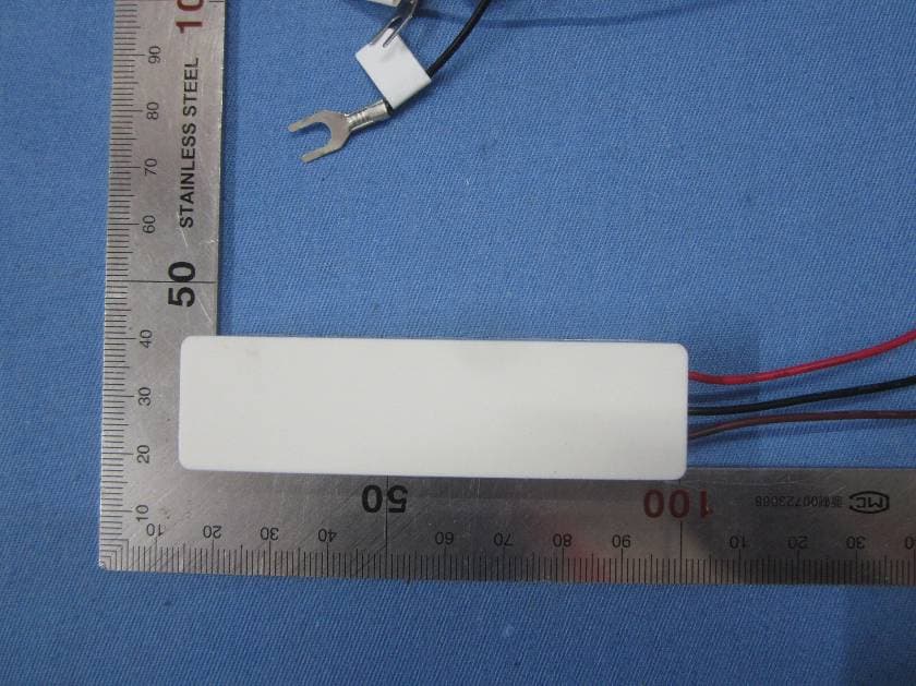
TXL3331
Jun 20, 2015Wireless Doorbell Extender
Equipment Class
DSC - Part 15 Security/Remote Control Transmitter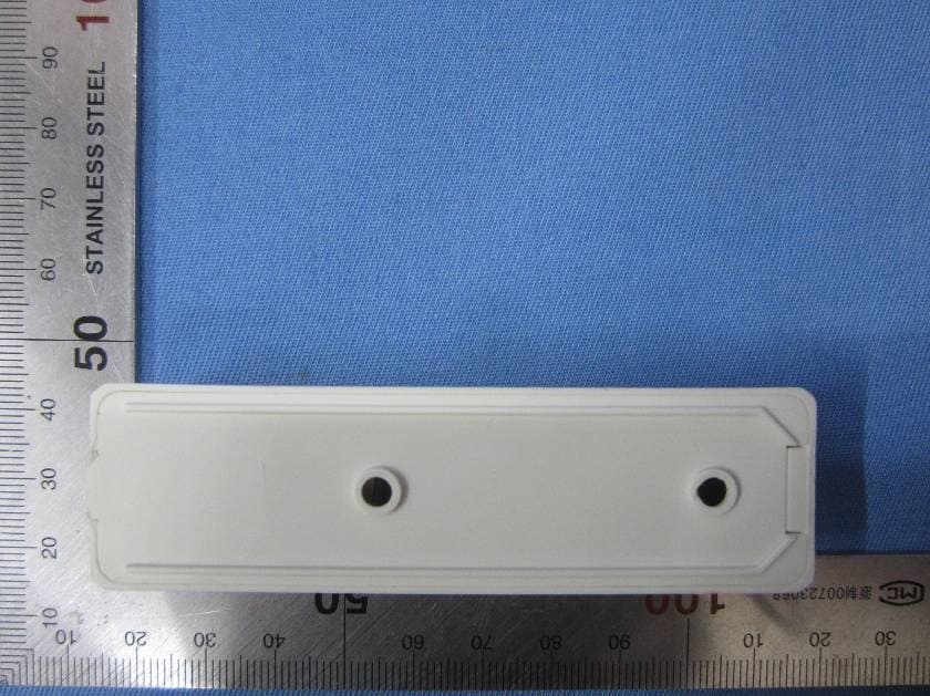
TXL3301
May 08, 2015Wireless Doorbell Chime Sensor
Equipment Class
DSC - Part 15 Security/Remote Control Transmitter
TXL3551
May 08, 2015Wireless Entry Alert Sensor
Equipment Class
DSC - Part 15 Security/Remote Control Transmitter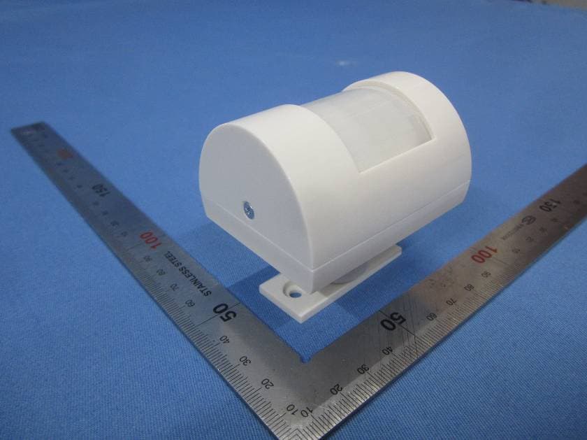
TXL3601
May 08, 2015Wireless Motion-Activated Sensor
Equipment Class
DSC - Part 15 Security/Remote Control Transmitter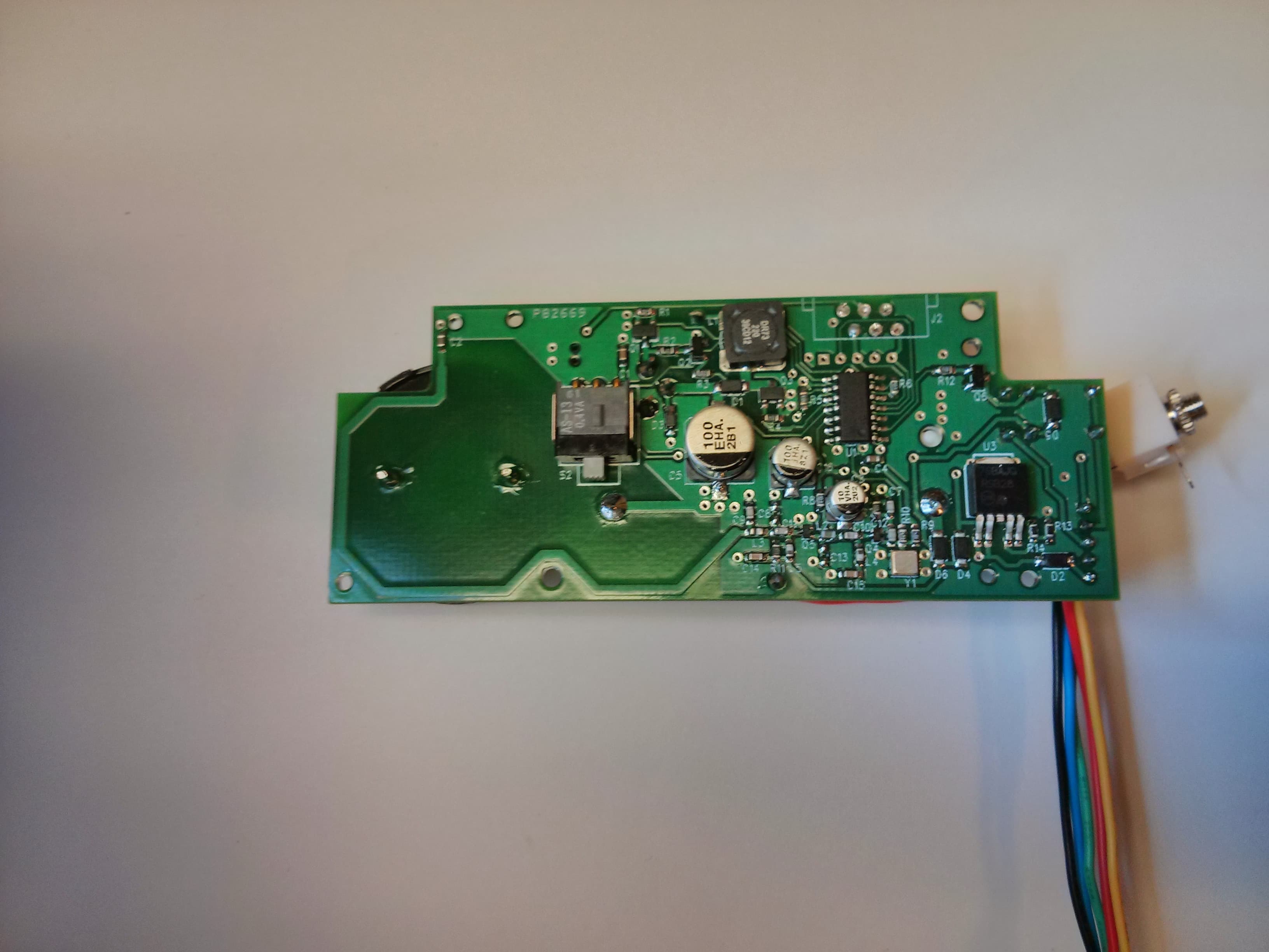
TXL34080
Jan 07, 2014Transmitter for use in a wireless alert system
Equipment Class
DSC - Part 15 Security/Remote Control Transmitter