TZ2SAFEMARKTR316-317MHz WIRELESS DEVICE
SafeMark Systems LP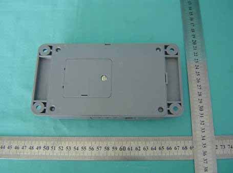
Click to zoom
Application Details
- Equipment Class
- DSC - Part 15 Security/Remote Control Transmitter
- Date of Grant
- Feb 27, 2006
- Application Purpose
- Original Equipment
- Date of Application
- Feb 27, 2006
- Equipment Note
- 316-317MHz WIRELESS DEVICE
- Frequency Range
- 316.84500000 - 316.84500000
- Company
- SafeMark Systems LP
- Country
- United States
Documents & Files
Document Text
Text extracted from the exhibit documents filed with the FCC. Open a document above to read the original.
Users Manual
SAFEMARK SYSTEMS LP Transmitter FCC ID: TZ2SAFEMARKTR Shenzhen Most Electronic Co., Ltd. Report No. MT-E0511457 User’s manual 1. Insert 8pcs of battery size AAA 2. Install the transmitter on the wall with four screws 3. Program transmitter with hotel serial number, transmitter own serial number, and next contact transmitter serial number 4. Test the working of transmitter with programmed safe. If the program is correct, the green LED will flash Note: Please test the transmitter before mount it on the wall. If the transmitter program correctly, then the green LED will flash when it receives the valid signal. FCC NOTE: THE MANUFACTURER IS NOT RESPONSIBLE FOR ANY RADIO OR TV INTERFERENCE CAUSED BY UNAUTHORIZED MODIFICATIONS TO THIS EQUIPMENT. SUCH MODIFICATIONS COULD VOID THE USER’S AUTHORITY TO OPERATE THE EQUIPMENT.
Users Manual
SAFEMARK SYSTEMS LP Transmitter FCC ID: TZ2SAFEMARKTR Shenzhen Most Electronic Co., Ltd. Report No. MT-E0511457 USER’S MANUAL 1. “*”+ “*” + 6683 + “*+ 6 2. Enter four digit serial code + “#” 3. Enter 3 digit of transmitter own code + “#” 4. Enter 3 digit of next transmitter code + “#” To set the next transmitter: Repeat step “3” and “4” TO SET SAFE TSETING MODE Press “*” +”*” + “311189”+”#” Press any key for 2 seconds, the tasting mode will be stopped. FCC NOTE: THE MANUFACTURER IS NOT RESPONSIBLE FOR ANY RADIO OR TV INTERFERENCE CAUSED BY UNAUTHORIZED MODIFICATIONS TO THIS EQUIPMENT. SUCH MODIFICATIONS COULD VOID THE USER’S AUTHORITY TO OPERATE THE EQUIPMENT.
External Photos
SAFEMARK SYSTEMS LP Transmitter FCC ID: TZ2SAFEMARKTR Photos Figure 1 General Appearance Figure 2 General Appearance Label Location
ID Label/Location Info
SAFEMARK SYSTEMS LP Transmitter FCC ID: TZ2SAFEMARKTR Shenzhen Most Electronic Co., Ltd. Report No. MT-E0511457 Label Drawing FCC ID: TZ2SAFEMARKTR Model Number: TX This device complies with Part 15 of the FCC Rules. Operation is subject to the following two conditions: (1) this device may not cause harmful interference, and (2) this device must accept any interference received, including interference that may cause undesired operation.
ID Label/Location Info
SAFEMARK SYSTEMS LP Transmitter FCC ID: TZ2SAFEMARKTR Photos Figure 1 General Appearance Figure 2 General Appearance Label Location
Internal Photos
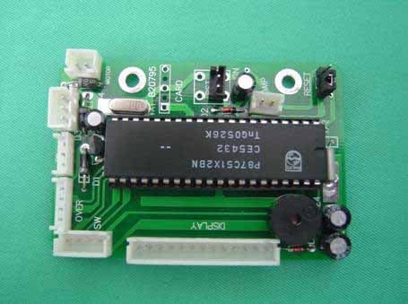
SAFEMARK SYSTEMS LP Transmitter FCC ID: TZ2SAFEMARKTR Photos Figure 3 Main Board, Component Side Figure 4 Main Board, Component Side SAFEMARK SYSTEMS LP Transmitter FCC ID: TZ2SAFEMARKTR Figure 5 Main Board, Component Side Figure 6 Main Board, Component Side SAFEMARK SYSTEMS LP Transmitter FCC ID: TZ2SAFEMARKTR Figure 7 Main Board, Component Side Figure 8 Main Board, Component Side SAFEMARK SYSTEMS LP Transmitter FCC ID: TZ2SAFEMARKTR Figure 9 Main Board, Component Side
Operational Description
SAFEMARK SYSTEMS LP Transmitter FCC ID: TZ2SAFEMARKTR Shenzhen Most Electronic Co., Ltd. Report No. MT-E0511456 DESCRIPTION OF TRANSMITTER OPERATION Technical Description: The brief circuit description is listed as follows: -“receiver” is a AM/ASK receiver. It operating in 315MHZ ISM band. -“TRANSMITTER’’ is a AM/ASK transmitter. It operating in 315MHZ ISM band . -T1 , T2, and associated circuit act as Decoder. Antenna Used: A permanent wire antenna has been user.
Schematics
SAFEMARK SYSTEMS LP Transmitter FCC ID: TZ2SAFEMARKTR Shenzhen Most Electronic Co., Ltd. Report No. MT-E0511457
Test Report
FCC ID: TZ2SAFEMARKTR Shenzhen Most Electronic Co., Ltd. Report No. MT-E0511457 Page 1 of 17 SAFEMARK SYSTEMS LP Transmitter Model Number: TX Prepared for : SYNAPSIS INDUSTRIAL CO., LTD. 2101 PARK CENTER DRIVE, SUITE 125 ORLANDO, FL 32835 Prepared By : Shenzhen Most Electronic Co., Ltd. 21A-B 4 th Building, Time City, Chuangye Road, Nanshan, Shenzhen Guangdong, China Tel: (0755)-86170306 Report Number MT-E0511457 Date of Test Jan. 17 ~ Feb. 08, 2006 Date of Report Feb. 08, 2006 FCC ID: TZ2SAFEMARKTR Shenzhen Most Electronic Co., Ltd. Report No. MT-E0511457 Page 2 of 17 TABLE OF CONTENTS Description Page Test Report Declaration 1. GENERAL INFORMATION ....................................................................................................... 4 1.1. Description of Device (EUT) ................................................................................................................ 4 1.2. Test Facility ........................................................................................................................................... 5 1.3. Test Uncertainty .................................................................................................................................... 5 2. POWER LINE CONDUCTED EMISSION TEST ..................................................................... 6 3. RADIATED EMISSION TEST .................................................................................................... 7 3.1. Test Equipment...................................................................................................................................... 7 3.2. Block Diagram of Test Setup ................................................................................................................ 7 3.3. Radiated Emission Limit ....................................................................................................................... 8 3.4. EUT Configuration on Test ................................................................................................................... 8 3.5. Operating Condition of EUT ................................................................................................................. 9 3.6. Test Procedure ....................................................................................................................................... 9 3.7. Radiated Emission Test Result ............................................................................................................ 10 4. BANDWIDTH TEST ................................................................................................................... 13 4.1. Test Equipment.................................................................................................................................... 13 4.2. Test Standard ....................................................................................................................................... 13 4.3. Bandwidth Limit: ................................................................................................................................ 13 APPENDIX I (2 pages) FCC ID: TZ2SAFEMARKTR Shenzhen Most Electronic Co., Ltd. Report No. MT-E0511457 Page 3 of 17 TEST REPORT DECLARATION Applicant SAFEMARK SYSTEMS LP Manufacturer SAFEGUARD SECURITY INDUSTRIAL CO LTD. EUT Description Transmitter (A) MODEL NO. : TX (B) SERIAL NO. : E2006010036 (C) POWER SUPPLY : DC 12V Test Procedure Used: FCC Rules and Regulations Part 15 Subpart C Apr, 2004. The device described above is tested by Audix Technology (Shenzhen) Co., Ltd. to determine the maximum emission levels emanating from the device. The maximum emission levels are compared to the FCC Part 15 Subpart C limits for radiated and conducted emissions. The test results are contained in this test report and Audix Technology (Shenzhen) Co., Ltd. is assumed full responsibility for the accuracy and completeness of tests. Also, this report shows that EUT is technically compliant with FCC requirements. This report applies to above tested sample only. This report shall not be reproduced in part without written approval of SHENZHEN MOST ELECTRONIC CO., LTD. This report must not be used by the applicant to claim product endorsement by NVLAP or any agency of the U.S. Government. Date of Test : Jan. 17 ~ Feb. 08, 2006 Prepared by : Mike Wang / Assistant Reviewer : Amy Zhu / Assistant Manager Approved & Authorized Signer : Mark Wen / Manager FCC ID: TZ2SAFEMARKTR Shenzhen Most Electronic Co., Ltd. Report No. MT-E0511457 Page 4 of 17 1. GENERAL INFORMATION 1.1. Description of Device (EUT) Description : Transmitter Model No. : TX Applicant : SYNAPSIS INDUSTRIAL CO., LTD. 2101 PARK CENTER DRIVE, SUITE 125 ORLANDO, FL 32835 Manufacturer : SAFEGUARD SECURITY INDUSTRIAL CO LTD. 7/F, KIN ON COMM. BLDG. 49-51 JERVOIS ST. SHEUNG WANHONG KONG Date of Test : Jan. 17 ~ Feb. 08, 2006 FCC ID: TZ2SAFEMARKTR Shenzhen Most Electronic Co., Ltd. Report No. MT-E0511457 Page 5 of 17 1.2. Test Facility Site Description 3m Anechoic Chamber : Certificated by FCC, USA Registration Number: 90454 Aug. 15, 2003 3m & 10m Anechoic Chamber : Certificated by FCC, USA Registration Number: 794232 Mar. 15, 2004 EMC Lab. : Certificated by DATech, German Registration Number: DAT-P-091/99-01 Feb. 02, 2004 Certificated by NVLAP, USA NVLAP Code: 200372-0 Mar. 31, 2004 Certificated by Nemko, Norway Aut. No.: ELA135 April. 22, 2004 Certificated by Industry Canada Registration Number: IC 5183 Jul. 28, 2004 Name of Firm : Audix Technology (Shenzhen) Co., Ltd. Site Location : No. 6, Ke Feng Rd., 52 Block, Shenzhen Science & Industrial Park, Nantou, Shenzhen, Guangdong, China 1.3. Test Uncertainty No. Item Uncertainty Remark 1. Uncertainty for Conducted Emission Test 1.22dB 2. Uncertainty for Radiated Emission Test 3.14dB 3m Chamber 3. Uncertainty for Radiated Emission Test 3.18dB 10m Chamber 4. Uncertainty for Power Clamp Test 1.38dB FCC ID: TZ2SAFEMARKTR Shenzhen Most Electron…
Text truncated - open the document above for the full version.
Test Setup Photos
FCC ID: TZ2SAFEMARKTR Shenzhen Most Electronic Co., Ltd. Report No. MT-E0511457 5Radiated Emission Test 5.1. Photos of Radiated Emission Test (In Anechoic Chamber)
Contact Information
Applicant
Lei Zhu Lee(Manager)
Test Firm
Audix Technology (Shenzhen) Co.Smart Tsai
Technical Specifications
| # | Rule Parts | Frequency Range | Power Output |
|---|---|---|---|
| 1 | 15.231 | 316.845 MHz - 316.845 MHz | - |
Other Applications from SafeMark Systems LP
TZ2SAFEMARK51D
Feb 20, 20063160317MHz WIRELESS DEVICE
Equipment Class
DSC - Part 15 Security/Remote Control Transmitter