U2ZZW5314Z-Wave 700s 4-Button Simple Controller
Sheenway Asia Ltd.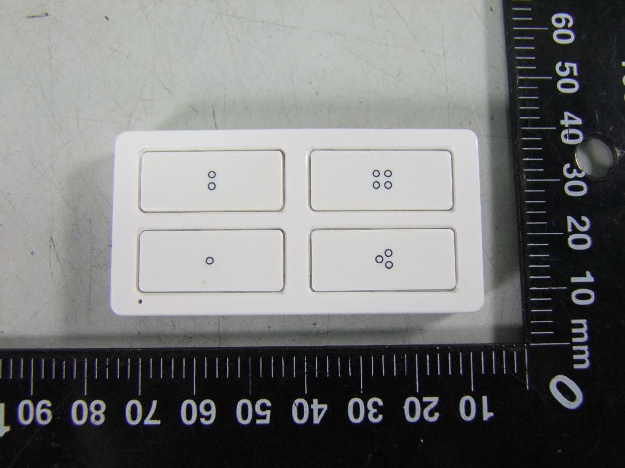
Click to zoom
Application Details
- Equipment Class
- DXT - Part 15 Low Power Transceiver, Rx Verified
- Date of Grant
- Oct 28, 2020
- Application Purpose
- Original Equipment
- Date of Application
- Oct 28, 2020
- Equipment Note
- Z-Wave 700s 4-Button Simple Controller
- Frequency Range
- 916.00000000 - 916.00000000
- Company
- Sheenway Asia Ltd.
- Country
- China
Documents & Files
Document Text
Text extracted from the exhibit documents filed with the FCC. Open a document above to read the original.
Users Manual
SPECIFICATIONS ZW5314 Battery operated: 2x CR2032 lithium 3V batteries Signal (frequency): 908.4/916MHz Range: Up to 150ft. line of sight between the wireless controller and the closest Z-Wave receiver module Operating temperature range: 32-104° F (0-40° C) For indoor use only Specifications subject to change without notice due to continuing product improvement SPÉCIFICATIONS ZW5314 Alimenté par pile : 2x piles CR2032 au lithium 3V Signal (fréquence) : 908.4/916MHz Portée : Distance à vue maximale de 150 pi (45.7m) entre la télécommande et le module de réception Z-Wave le plus proche Plage de températures de fonctionnement : De 32 à 104° F (de 0 à 40° C) Utilisation intérieure uniquement En raison d'améliorations continues du produit, les spécifications peuvent faire l'objet de changements sans préavis ESPECIFICACIONES ZW5314 Funciona con pilas: 2x pilas CR2032 de litio de 3V Señal (frecuencia): 908.4/916MHz Alcance: Hasta 150 pies (45.7m), sin obstrucciones, entre el controlador inalámbrico y el módulo receptor Z-Wave más cercano Rango de temperatura de funcionamiento: 32-104° F (0-40° C) Para uso en interiores exclusivamente Las especificaciones están sujetas a cambios sin previo aviso por las constantes mejoras a que se someten los productos Getting to know your new Z-Wave device • No wiring necessary. • Four function buttons. Each button supports up to three actions (up to 12 unique actions). • Fits multi-gang wallplates (not included) for installation beside exisiting switches. Installing or replacing battery 1. Turn remote to the right side to reveal a slot in the lower right corner of controller. 2. Insert a 1/4in. standard flat-blade screwdriver into the slot and twist to release housing clamps. Once edge is raised, gently move around the frame to release both halves. 3. Remove old batteries by sliding them out of the top and bottom of the holders. Place new batteries with (+) side facing up. 4. Snap the controller halves together. Wakeup interval information • Role type: Reporting Sleeping Slave (RSS) • Wakeup interval: Supports a range of 0, 3600 seconds – 86,400 seconds (off, 1-24 hours) • Default = 86,400 seconds (24 hours) • Keep the default wakeup period to maintain the longest possible battery life. However, the minimum configurable value should be no less than 3600s (1hr) or to OFF 0s. 1.1. NOT FOR USE WITH MEDICAL OR LIFE-SUPPORT EQUIPMENT Z-WAVE ENABLED DEVICES SHOULD NEVER BE USED TO SUPPLY POWER TO OR CONTROL THE ON/ OFF STATUS OF MEDICAL OR LIFE-SUPPORT EQUIPMENT. NE PAS UTILISER AVEC UN ÉQUIPEMENT MÉDICAL OU DE SURVIE LES DISPOSITIFS COMPATIBLES AVEC LA TECHNOLOGIE Z-WAVE NE DEVRAIENT JAMAIS ÊTRE UTILISÉS POUR ALIMENTER OU COMMANDER LA MISE EN MARCHE OU L'ARRÊT DE L'ÉQUIPEMENT MÉDICAL OU DE SURVIE. AVERTISSEMENT WARNINGADVERTENCIA A. LED indicator B. Buttons Single press — sends action 1 for that button to the hub/controller. Double press — sends action 2 for that button to the hub/controller. Triple press — sends action 3 for that button to the hub/controller. C. Battery tray notch (located on side) Actions Actions allow the user to select predetermined actions and assign them to start or stop with the press of a button. The controller sends the button press information to the hub, which executes the action. An action can be many combinations of scenes, groups or events, and is greatly dependent on the hub capabilities. This device supports Association Command Class (3 Groups) • Association Group 1 supports Lifeline, Battery Reports, Device Reset Locally Notification,Central Scene,Indicator Report • Association Group 2 supports Basic Set and is controlled by pressing the UP or Down button once. • Association Group 3 supports Basic Set and is controlled by double pressing the UP or Down button • Each Association Group supports 5 total nodes Z-WAVE INTEROPERABILITY This product can be included and operated in any Z-Wave network with other Z-Wave certified devices from other manufacturers and/or other applications. All non-battery operated nodes within the network will act as repeaters regardless of vendor to increase reliability of the network. 2.2. A C B • BATTERIES MAY LEAK HARMFUL LIQUIDS OR IGNITABLE MATERIALS OR EXPLODE CAUSING INJURY AND PRODUCT DAMAGE. • DO NOT MIX OLD AND NEW OR OTHER BATTERY TYPES. • REPLACE ALL BATTERIES AT THE SAME TIME. • REPLACE EXHAUSTED BATTERIES IMMEDIATELY. • REMOVE BATTERIES IF PRODUCT IS TO BE UNUSED FOR EXTENDED PERIODS. CAUTION Requires two CR2032 coin cells. Observe polarity markings ( + ), ( - ). Se necesitan dos pilas CR2032. Respetar las indicaciones de polaridad ( + ), ( - ). MISE EN GARDE Requiert deux piles CR2032 Observez les symboles de polarité ( + ), ( - ). OR OR 3.3. Adding your remote to a Z-Wave network 1. Follow the instructions for your Z-Wave certified hub to add a device to the Z-Wave network. 2. Once the hub is ready to add your device, press and hold either button for three seconds. 3. The LED will flash two times when the remote sends add notification (NIF). 4. The LED will keep lighting up for one minute if inclusion is successful. NOTE: Some hubs require an additional step for secure inclusion. When prompted, scan the QR code on the back of the remote or type the 5-digit pin code located on the back of the remote. 5. Following the instructions for your Z-Wave certified hub, assign actions for each button press. An action can be many combinations of scenes, groups or events, and is greatly dependent on the hub capabilities. If prompted by the controller to enter the S2 security code, refer to the QR code/ security number on the side of the box or the QR code label on the product (see Figure 1). Enter the 5-digit PIN code. Figure 1: Removing your remote from a Z-Wave network 1. Follow the instructions for your Z-Wave certified hub to remove a device from the Z-Wave network. 2. Once the hub is ready to remove your device, press and hold either button for three seconds. 3. The LED will flash two times when the …
Text truncated - open the document above for the full version.
Cover Letter(s)
Sheenway Asia Ltd Room 1313, 13/F, Austin Tower, Tsim Sha Tsui, Kowloon. Tel (86-755)82374246 Fax (86-755)82375277 Email: [email protected] Date: 07/22/2020 Federal Communications Commission 7435 Oakland Mills Road Columbia MD 21046 c.c. UL Verification Services Certification Division 47173 Benicia Street Fremont, CA 94538, USA To whom it may concern: I, the undersigned, hereby authorize of Shenzhen Academy of Metrology and Quality Inspection and hereafter referred to as SMQ, to act on our behalf in all manners relating to application for equipment authorization, including signing of all documents relating to these matters. Any and all acts carried out by of Shenzhen Academy of Metrology and Quality Inspection on our behalf shall have the same effect as acts of our own. I, the undersigned, hereby certify that we are not subject to a denial of federal benefits, that includes FCC benefits, pursuant to Section 5301 of the Anti-Drug Abuse Act of 1988, 21 U.S.C. 853(a). In authorizing SMQ as our agent, we still recognize that we are responsible to: a) comply with the relevant provisions of the certification program; b) make all necessary arrangements for the conduct of the evaluation, including provision for examining documentation and access to all areas, records (including internal audit reports) and personnel for the purposes of evaluation (e.g. testing, inspection, assessment, surveillance, reassessment) and resolution of complaints; c) make claims regarding certification only in respect of the scope for which certification has been granted; d) do not use our product certification in such a manner as to bring the Certification Division into disrepute and not make any statement regarding our product certification which the Certification Division may consider misleading or unauthorized; e) upon suspension or cancellation of certification, discontinue use of all advertising matter that contains any reference thereto and return any certification documents as required by the Certification Division; f) use certification only to indicate the products are certified as being in conformity with specified standards; g) endeavor to ensure that no certificate or report nor any part thereof is used in a misleading manner; h) ensure that any reference to our product certification in communication media such as documents, brochures or advertising, complies with the requirements of the Certification Division; i) keep a record of all complaints made known to the us relating to the product’s compliance with requirements of the relevant standard and to make these records available to the Certification Division when requested; j) take appropriate action with respect to such complaints and any deficiencies found in products or services that affect compliance with the requirements for certification; k) document the actions taken. This authorization is valid until further written notice from the applicant. Sincerely Yours, Sammel Tung, Manager Sheenway Asia Ltd REMARK: 1. This authorization letter will be sent along with your application when filing with the Certification Division. 2. Please follow the format and type it on company letterhead and send original to us. 3. Authorized signature must be in agreement with grantee code contact in FCC database.
Cover Letter(s)
Sheenway Asia Ltd Room 1313, 13/F, Austin Tower, Tsim Sha Tsui, Kowloon. Tel (86-755)82374246 Fax (86-755)82375277 Email: [email protected] Federal Communications Commission 7435 Oakland Mills Road Columbia MD 21046 Subject: Request for Confidentiality FCC ID: U2ZZW5314 To Whom It May Concern: Pursuant to the provisions of Sections 0.457 and 0.459 of the Commission’s rules (47 CFR §§ 0.457, 0.459), we are requesting the Commission to withhold the following attachments as confidential document from public disclosure indefinitely. Schematic Diagram Block Diagram Theory of Operation Above mentioned document contains detailed system and equipment description are considered as proprietary information in operation of the equipment. The public disclosure of above documents might be harmful to our company and would give competitor an unfair advantage in the market. It is our understanding that all measurement test reports, FCC ID label format and correspondent during certification review process cannot be granted as confidential documents and those information will be available for public review once the grant of equipment authorization is issued. Best Regards Sammel Tung Manager Sheenway Asia Ltd August, 14, 2020
External Photos
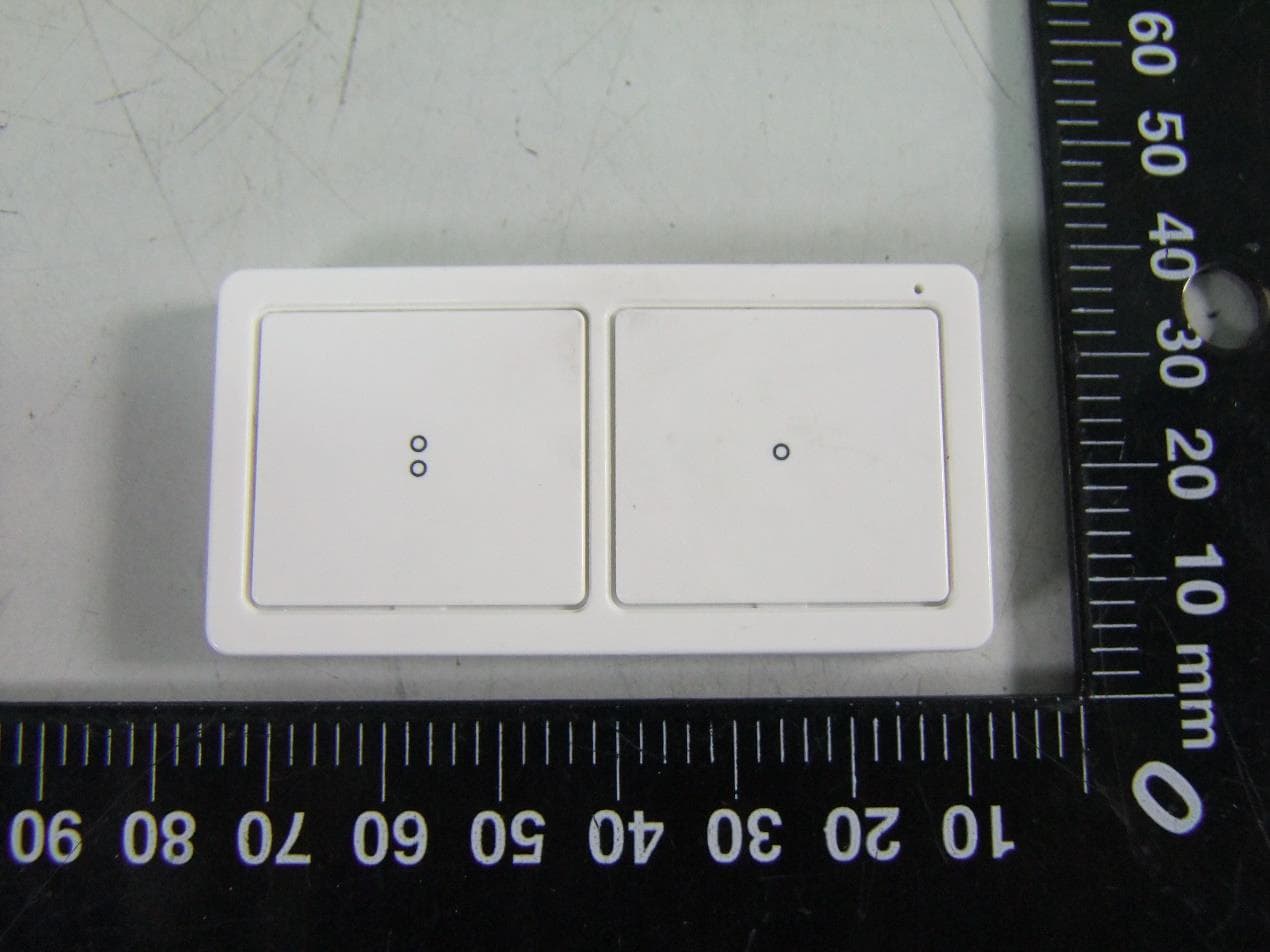
Photo 1 Appearance of EUT Photo 2 Appearance of EUT Photo 3 Appearance of EUT Photo 4 Appearance of EUT Photo 5 Appearance of EUT Photo 6 Appearance of EUT
ID Label/Location Info
Portable Hub Remote (4 Button) Télécommande pour concentrateur portative (4 boutons) Model/Modèle: ZW5314 FCC ID: U2ZZW5314 IC: 6924A-ZW5314 www.byjasco.com MADE IN CHINA FABRIQUÉ EN CHINE 5 3 8 31-1 Ve r.7. 0 .1 This is a Device Specific Key (DSK). Use this when adding to a controller supporting S2 security or SmartStart if prompted. SmartStart NEW ART SILKSCREEN Enclosure & Yoke Z-Wave product, Jasco Model no: 53831 / ZW5314 The silkscreen copy is aligned to the center of the body 53831 Enclosure v1 Paul Milligan 07/24/20 Matt Henson 105.008 mm 60.007 mm 45.191 mm PRODUCT MARKINGS: PMS 430C Housing Back ViewHousing 32.6 mm 65.2 13.671 MM 3.72 MM 7.5MM 11 MM 24.175 MM
Internal Photos
Photo 1 Inside of EUT Photo 2 Battery Photo 3 Inside of EUT Photo 4 Inside of EUT Photo 5 Inside of EUT Photo 6 Inside of EUT 908.4MHz、916.0MHz Antenna
Test Report
Report No.: WT208001575 Page 1/22 FCC TEST REPORT For Z-Wave 700s 4-Button Simple Controller Model Number: ZW5314 FCC ID: U2ZZW5314 Report Number : WT208001575 Test Laboratory : Shenzhen Academy of Metrology and Quality Inspection Site Location : NETC Building, No.4 Tongfa Rd., Xili, Nanshan, Shenzhen, China Tel : 0086-755-86928965 Fax : 0086-755-86009898-31396 Web : www.smq.com.cn Email : [email protected] Report No.: WT208001575 Page 2/22 Test report declaration Applicant : Sheenway Asia Ltd. Address : Room1313, 13/F, Austin Tower, 22-26 Austin Avenue, Tsim Sha Tsui, Kowloon, Hong Kong, China Manufacturer : Sheenway Asia Ltd. Address : Room1313, 13/F, Austin Tower, 22-26 Austin Avenue, Tsim Sha Tsui, Kowloon, Hong Kong, China EUT Description : Z-Wave 700s 4-Button Simple Controller Model No. : ZW5314 FCC ID : U2ZZW5314 Test Standards: FCC Part 15 (October 1, 2019 Edition) ANSI C63.10-2013 The EUT described above is tested by Shenzhen Academy of Metrology and Quality Inspection EMC Laboratory to determine the maximum emissions from the EUT. Shenzhen Academy of Metrology and Quality Inspection EMC Laboratory is assumed full responsibility for the accuracy of the test results. The test data, data evaluation, test procedures, and equipment configurations shown in this report were made in accordance with the procedures given in ANSI C63.10 and the energy emitted by the sample EUT tested as described in this report is in compliance with FCC Rules Part 15.249. The test report is valid for above tested sample only and shall not be reproduced in part without written approval of the laboratory. Project Engineer: Date: Oct.14, 2020 (Zhou Fangai) Oct.14, 2020 Checked by: Date: (Lin Yixiang) Oct.14, 2020 Approved by: Date: (Lin Bin) Report No.: WT208001575 Page 3/22 TABLE OF CONTENTS TEST REPORT DECLARATION ......................................................................................................... 2 1. TEST RESULTS SUMMARY ................................................................................................... 4 2. GENERAL INFORMATION ...................................................................................................... 5 2.1. Report information.......................................................................................................... 5 2.2. Laboratory Accreditation and Relationship to Customer ......................................... 5 2.3. Measurement Uncertainty ............................................................................................. 6 3. PRODUCT DESCRIPTION ....................................................................................................... 7 3.1. EUT Description ............................................................................................................. 7 3.2. Block Diagram of EUT Configuration .......................................................................... 7 3.3. Operating Condition of EUT ......................................................................................... 7 3.4. Special Accessories ....................................................................................................... 7 3.5. Equipment Modifications ............................................................................................... 7 3.6. Support Equipment List ................................................................................................. 7 3.7. Test Conditions ............................................................................................................... 7 4. TEST EQUIPMENT USED ....................................................................................................... 8 5. CONDUCTED EMISSION TEST ............................................................................................. 9 5.1. Test Standard and Limit ................................................................................................ 9 5.2. Test Procedure ............................................................................................................... 9 5.3. Test Arrangement .......................................................................................................... 9 5.4. Test Data ......................................................................................................................... 9 6. RADIATED EMISSION TEST ................................................................................................ 10 6.1. Test Standard and Limit .............................................................................................. 10 6.2. Test Procedure ............................................................................................................. 10 6.3. Test Arrangement ........................................................................................................ 10 6.4. Test Data ....................................................................................................................... 11 7. OCCUPIED BANDWIDTH ...................................................................................................... 18 7.1. Test Standard and Limit .............................................................................................. 18 7.2. Test Procedure ............................................................................................................. 18 7.3. Test Arrangement ........................................................................................................ 18 7.4. Test Data ....................................................................................................................... 18 8. BAND EDGE ............................................................................................................................. 20 8.1. Test Standard and Limit .............................................................................................. 20 8.2. Band Edge FCC 15.249(d) Limit .............................…
Text truncated - open the document above for the full version.
Test Setup Photos
Radiated Emission below 1GHz -Front Radiated Emission above 1-18GHz
Contact Information
Applicant
Sammel Tung
Technical Contact
Shenzhen Academy of Metrology and Quality InspectiFangai Zhou
[email protected]86 755 86009898
No.4 TongFa Road, Xili Town, Nanshan District, · Shenzhen, Guangdong · China
Test Firm
Shenzhen Academy of Metrology and Quality InspecMs. Alice Hou
[email protected]86 755 86928932
Technical Specifications
| # | Rule Parts | Frequency Range | Power Output |
|---|---|---|---|
| 2 | 15C | 916 MHz - 916 MHz | - |
Other Applications from Sheenway Asia Ltd.
U2ZZW5313
Oct 28, 2020Z-Wave 700s 2-Button Simple Controller
Equipment Class
DXT - Part 15 Low Power Transceiver, Rx Verified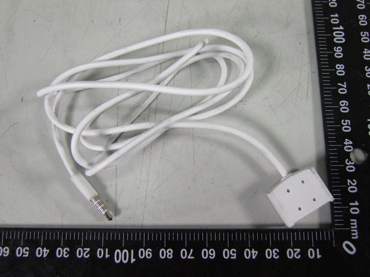
U2ZZW6309
Oct 27, 2020Z-Wave 700s Water Leak Sensor
Equipment Class
DXT - Part 15 Low Power Transceiver, Rx Verified
U2ZZW3012
Oct 13, 2020Z-Wave 700s In-Wall No Neutral Dimmer
Equipment Class
DXT - Part 15 Low Power Transceiver, Rx Verified
U2ZZW3011DV
Oct 12, 2020Z-Wave In-Wall Toggle Dimmer 0-10V 120/277V
Equipment Class
DXT - Part 15 Low Power Transceiver, Rx Verified
U2ZZW3010DV
Oct 11, 2020Z-Wave In-Wall Paddle Dimmer 0-10V 120/277V
Equipment Class
DXT - Part 15 Low Power Transceiver, Rx Verified