U3V-LLV21011Inductive Charger
The Ohio Willow Wood Company
Click to zoom
Application Details
- Equipment Class
- DCD - Part 15 Low Power Transmitter Below 1705 kHz
- Date of Grant
- Jan 17, 2013
- Application Purpose
- Original Equipment
- Date of Application
- Jan 09, 2013
- Equipment Note
- Inductive Charger
- Frequency Range
- 0.08400000 - 0.08400000
- Company
- The Ohio Willow Wood Company
- Country
- United States
Documents & Files
Document Text
Text extracted from the exhibit documents filed with the FCC. Open a document above to read the original.
Users Manual
1 LimbLogic Patient Instructions LimbLogic features an electronically controlled Vacuum Pump that uses air pressure and a sealing sleeve to securely suspend your prosthesis. The fob included with the system provides you with wireless control and monitoring of the vacuum level. Please review these instructions thoroughly and contact your prosthetist if you have any questions. 2 There are no field-serviceable parts inside the Vacuum Pump. Opening the Vacuum Pump will void the warranty. This pump is only designed to move air; use of Vaseline ® or similar lubricating creams inside the socket will clog the pump. Do not allow foreign substances to be pulled through the Vacuum Pump. This may impair function of your vacuum system. Do not allow acetone to contact the Vacuum Pump or fob. LimbLogic is not intended to be used as the only means of attachment of prosthesis to patient. All LimbLogic components have passed safety testing for use as medical devices. Radio enabled devices comply with United States and international guidelines for low power transceivers. If LimbLogic components will be used around safety critical devices such as pacemakers or defibrillators, consult the manufacturer for appropriate usage instructions. Consult the section on Regulatory Information for more information on safety and compliance. LimbLogic is designed for use by a single patient only. FCC NOTICE Note: This device complies with part 15 of the FCC Rules. Operation is subject to the following two conditions: (1) This device may not cause harmful interference, and (2) this device must accept any interference received, including interference that may cause undesired operation. Changes or modifications not approved by Ohio Willow Wood Company may void the user’s authority to operate this equipment. Remarque: Le présent appareil est conforme aux CNR d‘Industrie Canada applicables aux appareils radio . L‘exploitation est autorisée aux deux conditions suivantes: (1) l‘appareil ne doit pas produire de brouillage, et (2) l‘utilisateur de l‘appareil doit accepter tout brouillage radioélectrique subi, même si le brouillage est susceptible d‘en compromettre le fonctionnement. 3 TAbLE OF CONTENTS Page Installing the Fob Battery .........................................................................4 Quick-Start Guide .........................................................................................5 Fob Guide ........................................................................................................5 Charging the Vacuum Pump Battery ...................................................6 Charging the Vacuum Pump Battery Outisde the U.S. ...................7 Charging the Vacuum Pump Battery in a Vehicle ............................7 Turning On the Vacuum Pump .................................................................8 Turning Off the Vacuum Pump ................................................................8 Resetting the Vacuum Pump ....................................................................8 Turning On the Fob ......................................................................................8 Changing Vacuum Set Point ....................................................................9 Changing Regulation Mode......................................................................9 Bilateral Indicators ......................................................................................10 Detecting a Leak ..........................................................................................11 Vacuum Pump Battery Status .................................................................11 Exposure to Water .......................................................................................11 Exhaust Tube Muffler Cleaning ..............................................................12 Flushing the System ...................................................................................12 Troubleshooting Guide .............................................................................13 Regulatory Information.............................................................................17 4 INSTALLINg ThE FOb bATTERy The fob uses a commercially available CR2032 coin cell battery. The battery will normally have to be replaced every 3 to 6 months depending upon how much the fob is used. The fob case can be pried open using a small flat blade screw- driver, then snapped back together starting at the battery end and working back toward the opposite end. After the battery is replaced, the system does a quick check by illuminating all the LED indicators. If all of the LEDs do not illuminate, then either the battery or the LEDs are not working. Overview 5 QUICk-START gUIDE 3. To enter Standby Mode: To resume vacuum regulation: 2. Turn on the fob. 4. Turn off the Vacuum Pump. 1. Turn on the Vacuum Pump. Press one time. Pump will beep once. Press and hold center button until the yellow digits flash in a “chasing” pattern and then display the current vacuum level. The pump will operate until the preselected vacuum level has been reached. Press for approximately 2 seconds. The chasing pattern will be displayed as the pump returns to Active Mode. Press one time. Pump will beep twice. FOb gUIDE Press for approximately 2 seconds. The chasing pattern will be displayed, then the white Standy Indicator will light. Vacuum Pump battery Indicator Solid green = 50-100% charged Flashing green = 30-50% charged Solid red = 20-30% charged Flashing red = less than 20% charge remaining Current Vacuum Level bilateral Indicators Standby Indicator (White) Leak Indicator (Red) Up Enter Down Overview 6 ChARgINg ThE VACUUM PUMP bATTERy The Vacuum Pump should be charged before it is used for the first time, at the end of each day of use, and when the Battery Indicator on the fob is red. 1. Insert the charging plug all the way into the charging port. 2. Plug the charger into a power outlet. The blue light on the t…
Text truncated - open the document above for the full version.
Users Manual
1 This document provides instruction for the prosthetist in the installation and use of the system. A separate document, LimbLogic Patient Instructions, is included with each system and should be provided to the patient upon delivery of a prosthesis containing the LimbLogic. The Vacuum Pump and fob included in this package are electronically keyed together and can be used only with each other. LimbLogic Prosthetist Instructions WHAT'S IN THE BOX Vacuum Pump* Battery Charger* Fob Fob Battery Fob Key Ring Diagnostic Disc Exhaust Port Drain Tube Replacement Exhaust Hose and Muffler* Thermoplastic Fabrication Kit or Lamination Fabrication Kit* Patient Instructions Prosthetist Instructions *Quantity = 2 for bilateral kit 2 There are no field-serviceable parts inside the Vacuum Pump. Opening the Vacuum Pump will void the warranty. This pump is only designed to move air; use of Vaseline ® or similar lubricating creams inside the socket will clog the pump. Do not allow foreign substances to be pulled through the Vacuum Pump. This may impair function of your vacuum system. Do not allow acetone to contact the Vacuum Pump or fob. LimbLogic is not intended to be used as the only means of attachment of prosthesis to patient. All LimbLogic components have passed safety testing for use as medical devices. Radio enabled devices comply with United States and international guidelines for low power transceivers. If LimbLogic components will be used around safety critical devices such as pacemakers or defibrillators, consult the manufacturer for appropriate usage instructions. Consult the section on Regulatory Information for more information on safety and compliance. LimbLogic is designed for use by a single patient only. FCC NOTICE Note: This device complies with part 15 of the FCC Rules. Operation is subject to the following two conditions: (1) This device may not cause harmful interference, and (2) this device must accept any interference received, including interference that may cause undesired operation. Changes or modifications not approved by Ohio Willow Wood Company may void the user’s authority to operate this equipment. Remarque: Le présent appareil est conforme aux CNR d‘Industrie Canada applicables aux appareils radio . L‘exploitation est autorisée aux deux conditions suivantes: (1) l‘appareil ne doit pas produire de brouillage, et (2) l‘utilisateur de l‘appareil doit accepter tout brouillage radioélectrique subi, même si le brouillage est susceptible d‘en compromettre le fonctionnement. 3 TABLE OF CONTENTS Page Installing the Fob Battery .........................................................................4 Quick-Start Guide .........................................................................................5 Fob Guide ........................................................................................................5 Keys to Successful Use ..............................................................................6 Introduction ....................................................................................................6 Vacuum System Function .........................................................................6 Charging the Vacuum Pump Battery ....................................................7 Charging the Vacuum Pump Battery in a Vehicle ............................7 Turning On the Vacuum Pump .................................................................8 Turning Off the Vacuum Pump ................................................................8 Resetting the Vacuum Pump ....................................................................8 Turning On the Fob ......................................................................................8 Changing Vacuum Set Point ....................................................................9 Changing Regulation Mode......................................................................9 Bilateral Indicators ......................................................................................10 Changing the Prosthetist Settings ........................................................11 Detecting a Leak .........................................................................................12 Vacuum Pump Battery Status ................................................................12 Exposure to Water ......................................................................................12 Vacuum Plate/Pyramid .............................................................................13 Exhaust Tube Muffler Cleaning ..............................................................14 Flushing the System ...................................................................................14 Troubleshooting Guide .............................................................................15 Diagnostic Disc ............................................................................................19 Warranty ........................................................................................................20 Regulatory Information.............................................................................21 4 INSTALLINg THE FOB BATTERy The fob uses a commercially available CR2032 coin cell battery. The battery will normally have to be replaced every 3 to 6 months depending upon how much the fob is used. The fob case can be pried open using a small flat blade screw- driver, then snapped back together starting at the battery end and working back toward the opposite end. After the battery is replaced, the system does a quick check by illuminating all the LED indicators. If all of the LEDs do not illuminate, then either the battery or the LEDs are not working. Overview 5 QUICk-START gUIDE 3. To enter Standby Mode: To resume vacuum regulation: 2. Turn on the fob. 4. Turn off the Vacuum Pump. 1. Turn on the Vacuum Pump. Press one time. Pump will beep once. Press and hold center button until the yellow digits fla…
Text truncated - open the document above for the full version.
ID Label/Location Info
MODEL: LLV-21011 FCC ID: U3V-LLV21011 IC: 7475A-LLV21011 2012 PN-2279-A Label Location Charger label material is. Charger label Label material: 2-mil white polyester Ink: black Coating: 1-mil gloss clear polyester over lamination Permanent adhesive Printing Process: FLEXOGRAPHICE SPOT COLOR
RF Exposure Info
OWW inductive charger DoC January, 17 th 2013 1 Declaration of Compliance for the Ohio Willow Wood second generation Limb Logic Vacuum System with inductive charger Overview Ohio Willow Wood is submitting final documentation for our inductively charged prosthetic suspension system called the Limb Logic Vacuum Suspension system or LLVS. The LLVS is used to suspend prosthetic limbs on amputee patients. The system is charged with an inductive charger comprised of control electronics, a ferrite core primary winding located in the charger plug, and a receiving coil located in the product to be charged. (Figure 1 and Figure 2) Prior to submission of FCC compliance documents to the Curtis Straus TCB, Ohio Willow Wood submitted test and modeling data to the OET in compliance with the requirements of notice “680106 D01 RF Exposure Wireless Charging Apps v01.” This submittal is located in KDB 880208 ranging from 10/2011 to 11/2012. After significant assistance from the OET, Ohio Willow Wood received notification of compliance to the OET’s intended requirements for inductive charging on 11/15/2012. The KDB process resulted in a number of alternate designs and test reports. This document is intended to summarize the relevant portions of the discussion / documentation process in KDB 880208. For a complete record of the transaction, please refer to the KDB transcript. Compliance is demonstrated in this report by modeling after confirming model accuracy with field measurements near the tip of the charger plug, a region of the field that is relatively uniform. Sensor and field measures used to verify the Finite Element Model (FEM) data were witnessed at Curtis Straus, a Bureau Veritas company, located at One Distribution Center Circle, Suite #1, Littleton, MA 01460. All modeling was performed at Ohio Willow Wood using QuickField modeling software made by Tera Analysis Ltd located at Knasterhovvej 21, DK- 5700 Svendborg, Denmark. This document contains five sections: Section One is a functional description of the charger, load circuitry, and their function, Section Two is a description of the sensor used for the evaluation and the methods used to verify calibration, Section Three is a description of the Finite Element Model (FEM) and a comparison of modeled field data along the Z axis of the primary charger winding to measured values, Section Four discusses the rational agreed to by OWWCO and the OET and lists relevant limits for SAR and E fields based on FCC and ICNIRP guidelines, and Section Five is an analysis of the model data and a comparison to the limits described in Section Four. Section 1: System description. The G2 inductive charger design is based on a pair of coils used to form an inductive link between the charger electronics and the device to be charged. The primary coil is wound around a ferrite rod and is driven by an H-Bridge design at one of two fundamental frequencies: 84 kHz or 42 kHz. This coil is then potted into a plastic enclosure referred to as the plug. (Figure 1) At 84 kHz, current through the primary winding is limited by the inductance of the primary winding to levels below the ICNIRP recommended limits. When the primary is plugged into a compliant OWW inductive charger DoC January, 17 th 2013 2 load, the load detects the presence of a charger and then toggles a load across the secondary coil on and off at either 250 Hz or 350 Hz depending on whether the load is charged or charging. (Figure 2) This modulation in the impedance of the load is detected by the drive electronics of the charger as a “tone” and the charger controller then shifts the drive frequency to 42 kHz to allow higher power to be coupled to the load. When the plug is removed, the charger electronics detect the loss of the low frequency tone and reverts to 84 kHz. Figure 2 Charger "plug" inserted into load The charger (schematic 6226010) is powered by an external, 13.8 Vdc, medical grade supply (attached at JP1) and its output is plugged into a load (schematic 6226060001). The charger circuitry includes regulated supplies at 12.4 and 3.3 volts. (U4, U1 respectively) An H-Bridge is powered through a Schottky diode from the nominal 13.8 volt supply. This supply has a tolerance of ±5% and therefore a maximum voltage of 14.49 Vdc. This Schottky diode prevents reverse biases from the inductive load from impacting on the medical supply and other circuitry and has a forward voltage of 0.25 Vdc around the operating point of the charger. The resulting Figure 1 Charger "plug" OWW inductive charger DoC January, 17 th 2013 3 voltage driving the H-Bridge is nominally 13.55 Vdc but could range up to 14.24Vdc based on the tolerance of the supply. For this reason, the model was validated at 13.55 Vdc, but compliance was based on simulations at 14.24 Vdc. In normal function, the charger starts up in 84 kHz mode and watches for a tone. Once a tone is detected, indicating that the plug is plugged into a valid device, the charger shifts to 42 kHz mode. The charger shifts back to 84 kHz mode within 250 ms of losing the tone. Exposure of the user to 42 kHz would require that they either 1) pull the plug out of the unit under charge and then place it in contact with tissue in < 250ms, or 2) experience a double fault of the charger. In the 42 kHz band, the unit operates between the ICNIRP and IEEE limits. However, even at 42 kHz, the E fields generated in tissue only exceed the ICNIRP general public criteria by 19% and falls below the occupational exposure limits. Further, this exposure is only possible within several mm of the plug. For these reasons, the likelihood of harm due to a system failure is highly unlikely. The leaky I 2 T integration was added because, while the unit complies with the ICNIRP and IEEE limits, it was determined that the unit could still drive sufficient power in the 84 kHz mode to heat up a single turn of a fine wire wrapped around the charger tip to the point that it would cause discomfort to the touch. In …
Text truncated - open the document above for the full version.
Test Report
Curtis-Straus LLC is accredited by the American Association for Laboratory Accreditation for the specific scope of accreditation under Certificate Number 1627-01. This report may contain data which is not covered by the A2LA accreditation. ____________________________________________________________ Curtis-Straus LLC, a wholly owned subsidiary of BV CPS One Distribution Center Circle, #1 • •• • Littleton, MA • •• • TEL (978) 486-8880 • •• • FAX (978) 486-8828 page 1 of 17 Test Report Curtis-Straus LLC, a wholly owned subsidiary of BV CPS Report No EM1961-4 Client Ohio Willow Wood Mike Haynes Address 15441 Scioto Darby Rd. Mt. Sterling, Ohio 43143 Phone 800-553-3445 Items tested LLV-21011 FCC ID U3V-LLV21011 IC ID 7475A-LLV21011 FRN 0016158792 Equipment Code DCD FCC/IC Rule Parts 47 CFR 15.209 Test Dates August 8 & 17, 2012 Results As detailed within this report Prepared by Chris Reynolds – Test Engineer Authorized by Mairaj Hussain – EMC Supervisor Issue Date 12/13/2012 Conditions of Issue This Test Report is issued subject to the conditions stated in the ‘Conditions of Testing’ section on page 16 of this report. Test Report for The Ohio Willow Wood Company • •• • Report No. EM1961-4 January 7, 2013 ______________________________________________________________________ ____________________________________________________________ Curtis-Straus LLC, a wholly owned subsidiary of BV CPS One Distribution Center Circle, #1 • •• • Littleton, MA • •• • TEL (978) 486-8880 • FAX (978) 486-8828 page 2 of 17 Contents Contents..................................................................................................................................2 Summary.................................................................................................................................3 Test Methodology ....................................................................................................................3 Product Tested - Configuration Documentation .......................................................................4 Statement of Conformity......................................................................................................5 Modifications Required for Compliance ...................................................................................5 Test Results ............................................................................................................................6 Radiated Spurious Emissions..............................................................................................6 AC Line Conducted Emissions ..............................................................................................13 Measurement Uncertainty......................................................................................................14 Product Documentation .........................................................................................................15 Conditions Of Testing ............................................................................................................16 Form Final Report REV 7-20-07 (DW) Test Report for The Ohio Willow Wood Company • •• • Report No. EM1961-4 January 7, 2013 ______________________________________________________________________ Release Control Record Issue No. Reason for change Date Issued 1 Original Release January 7, 2013 _____________________________________________________________ Curtis-Straus LLC, a wholly owned subsidiary of BV CPS One Distribution Center Circle, #1 • •• • Littleton, MA • •• • TEL (978) 486-8880 • •• • FAX (978) 486-8828 page 3 of 17 Summary This test report supports an application for certification of a transmitter operating pursuant to 47 CFR 15.209. The product is the LLV-21011. It is a transmitter that operates in the range 84kHz, (tolerance of +/- 5KHz) when the inductive charger is not connected to the device to be charged. We found that the product met the above requirements without modification (see Modifications Required for Compliance section on page 5). Mike Haynes from The Ohio Willow Wood Company was present during the testing. The test sample was received in good condition. Test Methodology Radiated emission and AC Line conducted testing was performed according to the procedures specified in ANSI C63.4 (2003) and RSS-GEN. Radiated Emissions were maximized by rotating the device around three orthogonal axes as well as varying the test antenna’s height and polarity. The device antenna cannot be maximized separately. The following bandwidths were used during radiated spurious and line conducted emissions. Frequency RBW VBW 0.15-30MHz 9kHz 30kHz 30-1000MHz 120kHz 1MHz 1-25GHz 1MHz 3MHz Test Report for The Ohio Willow Wood Company • •• • Report No. EM1961-4 January 7, 2013 ______________________________________________________________________ _____________________________________________________________ Curtis-Straus LLC, a wholly owned subsidiary of BV CPS One Distribution Center Circle, #1 • •• • Littleton, MA • •• • TEL (978) 486-8880 • •• • FAX (978) 486-8828 page 4 of 17 Product Tested - Configuration Documentation EUT Configuration Work Order: M1961 Company: Ohio Willow Wood Company Address: 15441 Scioto Darby Rd. Mt. Sterling, OH 43143 Contact: Mike Haynes Person Present: Mike Haynes MNSN EUT: Charger (inductive) LLV-21011Sample 1 EUT Description: LimbLogic VS - Vacuum suspension system for prosthetic limbs EUT Max Frequency: 16MHz EUT ISM Frequency: 42kHz & 84 (±)KHz Support Equipment:MNSN HP Laptop compaq nc6320-- EUT Ports: Port LabelPort Type No. of ports No. PopulatedCable TypeShieldedFerritesLength Max Length In/Out NEBS Type Unpopulated Reason AC to DC brickDC power112-wire DC NoOn Dc side7'NAIndoor Software / Operating Mode Description: EUT is set to alternately turn the pump on to the set 20 inches of mercury then release and turn back on after reaching a software controlled setpoint. The Limblogic Prosthetist software on the support laptop co…
Text truncated - open the document above for the full version.
Test Report
Curtis-Straus LLC is accredited by the American Association for Laboratory Accreditation for the specific scope of accreditation under Certificate Number 1627-01. This report may contain data which is not covered by the A2LA accreditation. ____________________________________________________________ LLC • •• • Curtis-Straus LLC, a wholly owned subsidiary of BV CPS One Distribution Center Circle, #1 • •• • Littleton, MA • •• • TEL (978) 486-8880 • •• • FAX (978) 486-8828 page 1 of 28 Test Report Curtis-Straus LLC, a wholly owned subsidiary of BV CPS Report No EM1961-3 Client Ohio Willow Wood Mike Haynes Address 15441 Scioto Darby Rd. Mt. Sterling, Ohio 43143 Phone 800-553-3445 Items tested LLV-21011 FCC ID U3V-LLV21011 IC ID 7475A-LLV21011 FRN 0016158792 Equipment Code 8CC Prepared by Chris Reynolds – Test Engineer Authorized by Mairaj Hussain– EMC Supervisor Issue Date 12/13/2012 Conditions of Issue This Test Report is issued subject to the conditions stated in the ‘Conditions of Testing’ section on page 27 of this report. Test Report for Ohio Willow Wood • •• • Report No. EM1961-3 January 4, 2013 ______________________________________________________________________ ____________________________________________________________ Curtis-Straus LLC, a wholly owned subsidiary of BV CPS One Distribution Center Circle, #1 • •• • Littleton, MA • •• • TEL (978) 486-8880 • FAX (978) 486-8828 page 2 of 28 Contents Contents..................................................................................................................................2 Summary.................................................................................................................................3 Product Tested ........................................................................................................................4 Configuration Documentation...............................................................................................4 Compliance Statement ............................................................................................................5 Modifications Required for Compliance ...................................................................................6 RADIATED EMISSIONS..........................................................................................................7 CONDUCTED EMISSIONS ...................................................................................................15 Measurement Uncertainty......................................................................................................20 Product Documentation .........................................................................................................21 Jurisdictional Labeling and Required Instruction Manual Inserts............................................22 FCC Requirements ............................................................................................................22 FCC Part 18 Required Labeling for Industrial, Scientific and Medical Equipment ...............24 Canadian Requirements ....................................................................................................25 Conditions Of Testing ............................................................................................................27 REV 27-NOV-12 (KK) Test Report for Ohio Willow Wood • •• • Report No. EM1961-3 January 4, 2013 ______________________________________________________________________ Issue No. Reason for change Date Issued 1 Original Release January 4, 2013 _____________________________________________________________ Curtis-Straus LLC, a wholly owned subsidiary of BV CPS One Distribution Center Circle, #1 • •• • Littleton, MA • •• • TEL (978) 486-8880 • •• • FAX (978) 486-8828 page 3 of 28 Summary On August 8, 17, 2012 and November 8, 2012 we tested the LLV-21011 for compliance with the following requirements: EMC Emissions: • CFR 47 FCC Part 18 emissions requirements (USA) We found that the product met the above requirements without modification. Mike Haynes from Ohio Willow Wood was present during the testing. The test sample was received in good condition. The sample was received on August 8, 2012. The EUT is an inductive charger that, while charging, operates at 42kHz. For data in this report, the EUT was operating only in this mode of operation. Test Report for Ohio Willow Wood • •• • Report No. EM1961-3 January 4, 2013 ______________________________________________________________________ _____________________________________________________________ Curtis-Straus LLC, a wholly owned subsidiary of BV CPS One Distribution Center Circle, #1 • •• • Littleton, MA • •• • TEL (978) 486-8880 • •• • FAX (978) 486-8828 page 4 of 28 Product Tested Configuration Documentation EUT Configuration Work Order: M1961 Company: Ohio Willow Wood Company Address: 15441 Scioto Darby Rd. Mt. Sterling, OH 43143 Contact: Mike Haynes Person Present: Mike Haynes MNSN EUT: Charger (inductive) LLV-21011Sample 1 EUT Description: LimbLogic VS - Vacuum suspension system for prosthetic limbs EUT Max Frequency: 16MHz EUT ISM Frequency: 42kHz & 84 (±)KHz Support Equipment:MNSN HP Laptop compaq nc6320-- EUT Ports: Port LabelPort Type No. of ports No. PopulatedCable TypeShieldedFerritesLength Max Length In/Out NEBS Type Unpopulated Reason AC to DC brickDC power112-wire DC NoOn Dc side7'NAIndoor Software / Operating Mode Description: EUT is set to alternately turn the pump on to the set 20 inches of mercury then release and turn back on after reaching a software controlled setpoint. The Limblogic Prosthetist software on the support laptop communicates with the EUT via the wireless USB device (low…
Text truncated - open the document above for the full version.
Contact Information
Applicant
Michael L Haynes(Engineer)
Test Firm
BUREAU VERITAS CONSUMER PRODUCTS SERVICES, INC.Ozgur Ozturk
[email protected]978-486-8880
Technical Specifications
| # | Rule Parts | Frequency Range | Power Output |
|---|---|---|---|
| 1 | 15C | 0.084 MHz - 0.084 MHz | - |
Other Applications from The Ohio Willow Wood Company
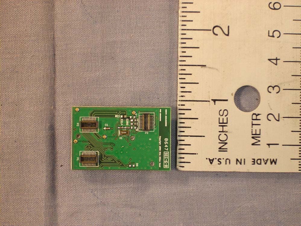
U3V6221020
Sep 30, 2007Transceiver Module
Equipment Class
DXT - Part 15 Low Power Transceiver, Rx Verified