U6M-SP3610SPEEDTRAC
Orion Technology Ltd.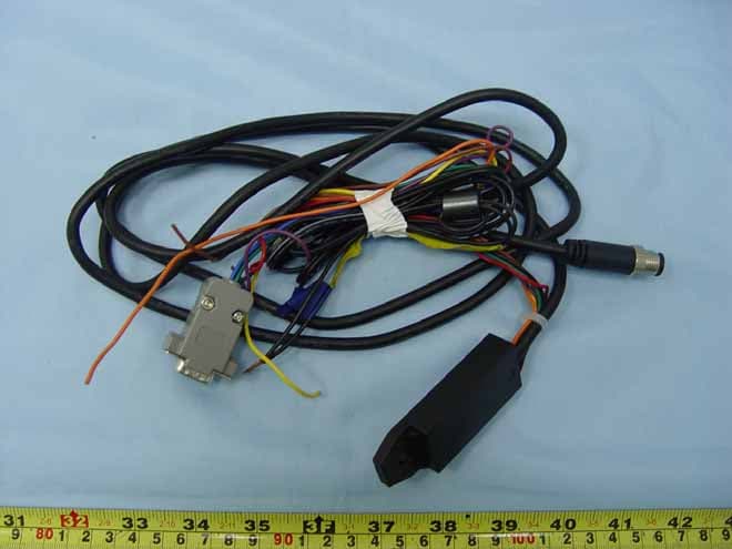
Click to zoom
Application Details
- Equipment Class
- PCB - PCS Licensed Transmitter
- Date of Grant
- Apr 09, 2008
- Application Purpose
- Original Equipment
- Date of Application
- Apr 08, 2008
- Equipment Note
- SPEEDTRAC
- Frequency Range
- 1850.20000000 - 1909.80000000
- Company
- Orion Technology Ltd.
- Country
- Taiwan
Documents & Files
Document Text
Text extracted from the exhibit documents filed with the FCC. Open a document above to read the original.
Users Manual
Speedtrac Getting Started By Hyper Terminal Ve r s i o n:6.07.01 Date:2008/1/23 © 2007 ORION Technology LTD. All rights reserved. 1/33 © 2007 ORION Technology LTD. All rights reserved. 2/33 Table of Contents 1. Introduction............................................................................................................ 3 I. Package contents:........................................................................................ 3 II. M12-V Cable pin assignment:..................................................................... 3 III. Speedtrac LED indicators:........................................................................ 4 IV. Speedtrac mode-selection switch:.......................................................... 5 2. Configuration by Hyper Terminal.......................................................................... 6 I. Hardware and Software preparation.......................................................... 6 II. Basic Configuration....................................................................................... 8 III. GPRS Connection Configuration.......................................................... 10 IV. Gateway Server Configuration.............................................................. 13 V. Function Variables Configuration – Mileage Report.............................. 14 VI. Function Variables Configuration – ParkFence Setting.................... 16 VII. Function Variables Configuration – GeoFence Setting..................... 18 3. Running on Normal Mode.................................................................................... 22 4. Test protocol commands via RS-232 connection................................................. 30 5. Get system logs via RS-232 connection for advanced debugging....................... 32 1. Introduction I. Package contents: 1. Speedtrac x 1 2. M12-V cable x 1 (with waterproof connector, 8-pin cable and surge protector) – For vehicle installation 3. M12-R cable x 1 (with waterproof connector, RS-232 connecor) – For configuration 4. AC adapter x 1 (Only available in the testing sample package) 5. Vehicle power adapter x 1 (Only available in the testing sample package) II. M12-V Cable pin assignment: PIN Color Name Description Range 1 Red□ PWR Power supply input DC, 12V~24V +- 5% Imax <= 2A 2 Black□ GND Ground 0V 3 Brown□ Digital Input 1 Reserved for Ignition Input (ACC Input) High : 12V~24V Low : 0V 4 Purple□ Digital Output 1 General purpose Digital Output 500 mA max @ 12V~24V 5 Blue□ Digital Output 2 General purpose digital Output 500 mA max @ 12V~24V 6 Green□ Digital Input 2 General purpose digital input (Positive trigger) High : 12V~24V Low : 0V 7 Yellow□ NC Reserved 8 Orange□ NC Reserved © 2007 ORION Technology LTD. All rights reserved. 3/33 © 2007 ORION Technology LTD. All rights reserved. 4/33 III. Speedtrac LED indicators: PWR ON: System Error OFF: System Error Flash: System running( 1sec ON 1sec OFF) GSM OFF: GSM module OFF or Error, No SIM Card, Searching networks) Flash: GSM registered (0.5sec ON 0.5sec OFF) Flash: GPRS connecting (0.25sec ON 0.25sec OFF) ON: Socket session online (connect to tcpserver running on the Gateway Server which is the Primary Server of a tracker) GPS OFF: GPS module OFF or Error Flash: Searching GPS signal ON: GPS fixed FCC warning statement This model complies with part 15/22H/24E of the FCC Rules. Operation is subject to the condition that this device does not cause harmful interference. This device complies with Part 15 of the FCC Rules. Operation is subject to the following two conditions: (1) this device may not cause harmful interference and (2) this device must accept any interference received, including interference that may cause undesired operation. Speedtrac mode-selection switch: 1. There is a switch when opening the battery cover of Speedtrac. It is designed to select different modes of Speedtrac. There are 3 modes of Speedtrac. A. Installation mode: Use M12-V cable to install Speedtrac in the vehicle. 2 Digital Inputs (Including 1 x ignition input) and 2 Digital outputs are available in Installation mode. B. Debug mode: Use M12-R cable to connect to PC COM port for configuration. C. Download mode: Use M12-R cable to connect to PC COM port to download the new firmware of Speedtrac. 2. The three-mode selections are listed below: A. Installation mode (with 2xDI and 2xDO): 1 2 3 4 5 6 ON V V V OFF V V V B. Debug mode (Configuration): 1 2 3 4 5 6 ON V V V OFF V V V C. Download mode (Update firmware): 1 2 3 4 5 6 ON V V V OFF V V V © 2007 ORION Technology LTD. All rights reserved. 5/33 2. Configuration by Hyper Terminal I. Hardware and Software preparation 1. Remove the battery cover of Speedtrac and insert a SIM card with GPRS service enabled. Lock the SIM card. 2. Adjust the mode-selection switch to ‘Debug mode’ (1-3-6 ON, 2-4-5 OFF). 3. Use a M12-R cable (with a RS-232 connector) to connect Speedtrac to a PC COM port. 4. Open Hyper Terminal (or other terminal program) at Windows Start Menu: All Programs\Accessories\Communications\Hyper Terminal. 5. Add a new connection, enter Name as ‘Speedtrac’. Click “OK” and select the COM Port for the Speedtrac connection. © 2007 ORION Technology LTD. All rights reserved. 6/33 6. Set the Baud rate as 38,400 bps and Flow control as none. Press “OK”. © 2007 ORION Technology LTD. All rights reserved. 7/33 © 2007 ORION Technology LTD. All rights reserved. 8/33 7. Connect the M12-R cable power-plug to the AC adapter and press the ‘ESC’ key of the PC keyboard within 3 second after the tracker is POWER ON until the text messages show on the Hyper Terminal screen. In doing so, Speedtrac boots on ‘Debug Mode’ (Configuration Mode). 8. Normally, the first LED is flashing constantly which means the Speedtrac is POWER ON and running. It shows the following messages on the Hyper Terminal. Speedtrac Version : EZ960903 - Build Date : Spe 03 2007 - Build Time : 18:11:39 - Serial Number : EZ2000000139 - Unit ID : 2000000139 - …
Text truncated - open the document above for the full version.
External Photos
FCC Test Report Report No.: FG810406 SPORTON International Inc. Page Number : A1 of A9 TEL : 886-2-2696-2468 Report Issued Date : Mar. 11, 2008 FAX : 886-2-2696-2255 Report Version : Rev. 01 FCC ID : U6M-SP3610 Appendix A. External Photographs of EUT FCC Test Report Report No.: FG810406 SPORTON International Inc. Page Number : A2 of A9 TEL : 886-2-2696-2468 Report Issued Date : Mar. 11, 2008 FAX : 886-2-2696-2255 Report Version : Rev. 01 FCC ID : U6M-SP3610 FCC Test Report Report No.: FG810406 SPORTON International Inc. Page Number : A3 of A9 TEL : 886-2-2696-2468 Report Issued Date : Mar. 11, 2008 FAX : 886-2-2696-2255 Report Version : Rev. 01 FCC ID : U6M-SP3610 FCC Test Report Report No.: FG810406 SPORTON International Inc. Page Number : A4 of A9 TEL : 886-2-2696-2468 Report Issued Date : Mar. 11, 2008 FAX : 886-2-2696-2255 Report Version : Rev. 01 FCC ID : U6M-SP3610 FCC Test Report Report No.: FG810406 SPORTON International Inc. Page Number : A5 of A9 TEL : 886-2-2696-2468 Report Issued Date : Mar. 11, 2008 FAX : 886-2-2696-2255 Report Version : Rev. 01 FCC ID : U6M-SP3610 FCC Test Report Report No.: FG810406 SPORTON International Inc. Page Number : A6 of A9 TEL : 886-2-2696-2468 Report Issued Date : Mar. 11, 2008 FAX : 886-2-2696-2255 Report Version : Rev. 01 FCC ID : U6M-SP3610 GSM Antenna GPS Antenna FCC Test Report Report No.: FG810406 SPORTON International Inc. Page Number : A7 of A9 TEL : 886-2-2696-2468 Report Issued Date : Mar. 11, 2008 FAX : 886-2-2696-2255 Report Version : Rev. 01 FCC ID : U6M-SP3610 FCC Test Report Report No.: FG810406 SPORTON International Inc. Page Number : A8 of A9 TEL : 886-2-2696-2468 Report Issued Date : Mar. 11, 2008 FAX : 886-2-2696-2255 Report Version : Rev. 01 FCC ID : U6M-SP3610 FCC Test Report Report No.: FG810406 SPORTON International Inc. Page Number : A9 of A9 TEL : 886-2-2696-2468 Report Issued Date : Mar. 11, 2008 FAX : 886-2-2696-2255 Report Version : Rev. 01 FCC ID : U6M-SP3610
Internal Photos
FCC Test Report Report No.: FG810406 SPORTON International Inc. Page Number : B1 of B12 TEL : 886-2-2696-2468 Report Issued Date : Mar. 11, 2008 FAX : 886-2-2696-2255 Report Version : Rev. 01 FCC ID : U6M-SP3610 Appendix B. Internal Photographs of EUT FCC Test Report Report No.: FG810406 SPORTON International Inc. Page Number : B2 of B12 TEL : 886-2-2696-2468 Report Issued Date : Mar. 11, 2008 FAX : 886-2-2696-2255 Report Version : Rev. 01 FCC ID : U6M-SP3610 FCC Test Report Report No.: FG810406 SPORTON International Inc. Page Number : B3 of B12 TEL : 886-2-2696-2468 Report Issued Date : Mar. 11, 2008 FAX : 886-2-2696-2255 Report Version : Rev. 01 FCC ID : U6M-SP3610 GSM Antenna GPS Antenna FCC Test Report Report No.: FG810406 SPORTON International Inc. Page Number : B4 of B12 TEL : 886-2-2696-2468 Report Issued Date : Mar. 11, 2008 FAX : 886-2-2696-2255 Report Version : Rev. 01 FCC ID : U6M-SP3610 FCC Test Report Report No.: FG810406 SPORTON International Inc. Page Number : B5 of B12 TEL : 886-2-2696-2468 Report Issued Date : Mar. 11, 2008 FAX : 886-2-2696-2255 Report Version : Rev. 01 FCC ID : U6M-SP3610 FCC Test Report Report No.: FG810406 SPORTON International Inc. Page Number : B6 of B12 TEL : 886-2-2696-2468 Report Issued Date : Mar. 11, 2008 FAX : 886-2-2696-2255 Report Version : Rev. 01 FCC ID : U6M-SP3610 FCC Test Report Report No.: FG810406 SPORTON International Inc. Page Number : B7 of B12 TEL : 886-2-2696-2468 Report Issued Date : Mar. 11, 2008 FAX : 886-2-2696-2255 Report Version : Rev. 01 FCC ID : U6M-SP3610 FCC Test Report Report No.: FG810406 SPORTON International Inc. Page Number : B8 of B12 TEL : 886-2-2696-2468 Report Issued Date : Mar. 11, 2008 FAX : 886-2-2696-2255 Report Version : Rev. 01 FCC ID : U6M-SP3610 FCC Test Report Report No.: FG810406 SPORTON International Inc. Page Number : B9 of B12 TEL : 886-2-2696-2468 Report Issued Date : Mar. 11, 2008 FAX : 886-2-2696-2255 Report Version : Rev. 01 FCC ID : U6M-SP3610 FCC Test Report Report No.: FG810406 SPORTON International Inc. Page Number : B10 of B12 TEL : 886-2-2696-2468 Report Issued Date : Mar. 11, 2008 FAX : 886-2-2696-2255 Report Version : Rev. 01 FCC ID : U6M-SP3610 FCC Test Report Report No.: FG810406 SPORTON International Inc. Page Number : B11 of B12 TEL : 886-2-2696-2468 Report Issued Date : Mar. 11, 2008 FAX : 886-2-2696-2255 Report Version : Rev. 01 FCC ID : U6M-SP3610 FCC Test Report Report No.: FG810406 SPORTON International Inc. Page Number : B12 of B12 TEL : 886-2-2696-2468 Report Issued Date : Mar. 11, 2008 FAX : 886-2-2696-2255 Report Version : Rev. 01 FCC ID : U6M-SP3610
RF Exposure Info
Document No.: 810406 RF Exposure Test Report Date: March 28, 2008 FCC ID: U6M-SP3610 Sporton International Inc. RF Exposure Test Report for ORION SP3610B Equipment : SPEEDTRAC Trade Name : ORION Model No. : SP3610B FCC ID : U6M-SP3610 Filing Type : Certification Applicant : Orion Technology LTD. 8F., No. 18, Sec. 1, Chang-An East Road, ZhongShan District, Taipei City 104, Taiwan Without written approval of SPORTON International Inc., the test report shall not be reproduced except in full. SPORTON International Inc. 6F, No.106, Sec. 1, Hsin Tai Wu Rd., Hsi Chih, Taipei Hsien, Taiwan, R.O.C. Document No.: 810406 RF Exposure Test Report Date: March 28, 2008 FCC ID: U6M-SP3610 Sporton International Inc. Maximum Permissible Exposure Test Report for SP3610B 1.0 Introduction The report has been prepared on behalf of ORION SP3610B to show compliance with the RF Exposure. 1.1 Requirements Three different categories of transmitters are defined by the FCC in OET Bulletin 65. These categories are fixed installation, mobile and portable and are defined as follows: Fixed installation: fixed location means that the device, including its antenna, is physically secured at a permanent location and is not able to be easily moved to another location. Additionally, distance to humans form the antenna is maintained to at least 2 meters. Mobile Devices: a mobile device is defined as a transmitting device designed to be used in other than fixed locations and to be generally used in such a way that a separation distance of at least 20 centimeters is normally maintained between the transmitter’s radiating structures and the body of the user or nearby persons. Transmitters designed to be used by consumers or workers that can be easily re-located are considered mobile devices if they meet the 20 centimeter separation requirement. The FCC rules for evaluating mobile devices for RF compliance are found in 47 CFR 2.1091. Portable Devices: a portable device is defined as a transmitting device designed to be used so that the radiating structure(s) of the device is/are within 20 centimeters of the body of the user. Portable device requirements are found in Section 2.1093 of the FCC’s Rules (47 CFR 2.1093) For this test report the ORION SP3610B is being done as a handheld device and it can be approved by MPE calculation. The MPE is evaluated at the 20cm test distance. The FCC also categorizes the use of the device as based upon the user’s awareness and ability to exercise control over his or her exposure. The two categories defined are Occupational/Controlled Exposure and General Population/Uncontrolled Exposure. These two categories are defined as Document No.: 810406 RF Exposure Test Report Date: March 28, 2008 FCC ID: U6M-SP3610 Sporton International Inc. follows: Occupational/controlled Exposure: In general, occupational/controlled exposure limits are applicable to situation in which persons are exposed as a consequence of their employment, who have been made fully aware of the potential for exposure. Awareness of the potential for RF exposure in a workplcae or similar environment can be provided through specific training as part of a RF safety program. If appropriate, warning signs and labels can also be used to establish such awareness by providing prominent information on the risk of potential exposure and instructions on methods to minimize such exposure risks. General Population/Uncontrolled Exposure: The general population / uncontrolled exposure limits are applicable to situations in which the general public may be exposed or in which persons who are exposed as a consequence of their employment may not be made fully aware of the potential for exposure or cannot exercise control over their exposure. Members of the general public would come under this category when exposure is not employment-related; for example, in the case of a wireless transmitter that exposes persons in its vicinity. Warning labels placed on low-power consumer devices such as cellular telephones are not considered sufficient to allow the device to be considered under the occupational/controlled category, and the general population/uncontrolled exposure limits apply to these devices. Since there are no warnings or training associated with this unit and it can be used by anyone, ORION SP3610B is evaluated to the General Population / Uncontrolled Exposure limits. 1.2 Radio Frequency Radiation Exposure Evaluation According to 1.1310 of the FCC rules, the power density limit for General Population/Uncontrolled Exposure is 1mW/cm 2 . As this is a handheld application, the MPE shall be calculated at 20cm to show compliance with the power density limit. The following formula was used to calculate the Power Density: S=EIRP/4πR 2 Where: S = Power Density EIRP = Effective Isotropic Radiated Power Document No.: 810406 RF Exposure Test Report Date: March 28, 2008 FCC ID: U6M-SP3610 Sporton International Inc. R = Distance from Transmitting Antenna For this device, the calculation is as follows: Because the EUT belongs to General Population/ Uncontrolled Exposure, the limit of power density is 0.57 mW/cm² and 1.0 mW/cm². Band Antenna Gain (dBi) Antenna Gain (numberic) Peak output power (dBm) Peak output power (mW) Calculated RF Exposure at 20 cm (mW/cm2) Limit (mW/cm2) GSM850 0.7 1.17 32.44 1753.88 0.41 0.57 PCS1900 0.7 1.17 29.98 995.41 0.23 1 Based on the above calculation at 20cm, the SP3610B is below the Power Density limit of 0.57mW/cm 2 and 1mW/cm 2 .
Test Report
FCC Test Report Report No. : FG810406 SPORTON International Inc. TEL : 886-2-2696-2468 FAX : 886-2-2696-2255 Report Version: Rev. 01 FCC Test Report According to 47 CFR Part 22H, 24E Equipment : SPEEDTRAC Trade Name : ORION Model No. : SP3610B FCC ID : U6M-SP3610 Tx Frequency Range : GSM850 : 824.2 ~ 848.8MHz PCS1900 : 1850.2 ~1909.8 MHz Max. ERP/EIRP Power : GSM850 : 0.17 W PCS1900 : 0.67 W Emission Designator : 300KGXW Applicant : Orion Technology LTD. 8F., No. 18, Sec. 1, Chang-An East Road, ZhongShan District, Taipei City 104, Taiwan The test result refers exclusively to the test presented test model / sample. Without written approval of SPORTON International Inc., the test report shall not be reproduced except in full. Certificate or Test Report must not be used by the applicant to claim the product in this test report endorsement by NVLAP or any agency of U.S. government. The data shown in this test report were carried out on Mar. 10, 2008 at Sporton International Inc. LAB. Report No.: FG810406, Report Version: Rev. 01. Roy Wu Manager SPORTON International Inc. 6F, No.106, Sec. 1, Hsin Tai Wu Rd., Hsi Chih, Taipei Hsien, Taiwan, R.O.C. FCC Test Report Report No. : FG810406 SPORTON International Inc. Page Number : i TEL : 886-2-2696-2468 Report Issued Date : Mar. 11, 2008 FAX : 886-2-2696-2255 Report Version : Rev. 01 FCC ID : U6M-SP3610 Table of Contents History of This Test Report .............................................................................................................................................. ii 1. General Information ....................................................................................................................................................1 1.1 Applicant............................................................................................................................................................1 1.2 Manufacturer .....................................................................................................................................................1 1.3 Basic Description of Equipment under Test.......................................................................................................1 1.4 Feature of Equipment under Test ......................................................................................................................1 1.5 Report Date .......................................................................................................................................................1 2. Test Configuration of Equipment under Test ...........................................................................................................2 2.1 Test Manner......................................................................................................................................................2 2.2 Test Mode .........................................................................................................................................................2 2.3 Connection Diagram of Test System .................................................................................................................2 2.4 Ancillary Equipment List ....................................................................................................................................2 3. General Information of Test Site................................................................................................................................3 3.1 Test Voltage......................................................................................................................................................3 3.2 Test Compliance................................................................................................................................................3 3.3 Frequency Range..............................................................................................................................................3 3.4 Test Distance.....................................................................................................................................................3 4. Test Data and Test Result ..........................................................................................................................................4 4.1 List of Measurements and Examinations ...........................................................................................................4 4.2 RF Output Power...............................................................................................................................................5 4.3 ERP / EIRP Measurement.................................................................................................................................6 4.4 Occupied Bandwidth and Band Edge Measurement .........................................................................................9 4.5 Conducted Emission........................................................................................................................................26 4.6 Field Strength of Spurious Radiation ...............................................................................................................36 4.7 Frequency Stability (Temperature Variation) ...................................................................................................41 4.8 Frequency Stability (Voltage Variation) ...........................................................................................................43 5. List of Measurement Equipments............................................................................................................................45 6. Uncertainty Evaluation .............................................................................................................................................46 Appendix A - External Photographs of EUT Appendix B - Internal Photographs of E…
Text truncated - open the document above for the full version.
Test Setup Photos
FCC Test Report Report No.: FG810406 SPORTON International Inc. Page Number : C1 of C1 TEL : 886-2-2696-2468 Report Issued Date : Mar. 11, 2008 FAX : 886-2-2696-2255 Report Version : Rev. 01 FCC ID : U6M-SP3610 Spurious Radiation FRONT VIEW REAR VIEW Appendix C. Setup Photographs
Contact Information
Applicant
Chous Yang(Engineer)
Test Firm
Sporton International IncKathy Lin
Technical Specifications
| # | Rule Parts | Frequency Range | Power Output | Emission | Tolerance |
|---|---|---|---|---|---|
| 2 | 24E | 1.85 GHz - 1.91 GHz | 670.00 mW | 300KGXW | 0.04 ppm |
Other Applications from Orion Technology Ltd.

U6M-EZ3610
May 01, 2007EASYTRAC
Equipment Class
PCB - PCS Licensed Transmitter