U6SJW1575FM Transmitter
Shenzhen J.W. Industries Co., Ltd.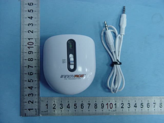
Click to zoom
Application Details
- Equipment Class
- DXX - Part 15 Low Power Communication Device Transmitter
- Date of Grant
- Apr 10, 2007
- Application Purpose
- Original Equipment
- Date of Application
- Apr 10, 2007
- Equipment Note
- FM Transmitter
- Frequency Range
- 88.50000000 - 91.00000000
- Country
- China
Documents & Files
Document Text
Text extracted from the exhibit documents filed with the FCC. Open a document above to read the original.
Block Diagram
Transmitter Block Diagram Audio Input 2Q1 Modulation & RF AMPLIFIER RF Oscillate Audio Signal Attenuation & Select Frequency Switch ANT BATTERY 3V
Cover Letter(s)
Klaus Knoerig Von: "Generic Office of Engineering Technology" <[email protected]> An: <[email protected]> Gesendet: Dienstag, 10. April 2007 19:38 Betreff: Response to Inquiry to FCC (Tracking Number 928807) Seite 1 von 1 2007-04-11 Inquiry: For specific FM transmitter information please refer to attached cover letter and test report. Response: Go ahead and file the grant. Submit a copy of this inquiry into the filing. Ensure all exhibits comply with FCC rules and policies. Do not reply to this message. Please select the Reply to an Inquiry Response link from the OET Inquiry System to add any additional information pertaining to this inquiry.
Cover Letter(s)
1) How does this device operate? The FM transmitter is a FM stereo transmitting configuration, which radiates FM wave on the air by modulating the any required signal to the carrier signal. The transmission frequency is set 88.5M, 91.0MHz. Operating Instructions: 1. Install two AAA batteries according to the indicated poles in the battery box. 2. Connect the audio cable of the transmitter to the audio-out or earphone jack of the sound source equipment(such as iPod, MP3, MD, CD, DVD and PS) 3. Switch on the power and the indicator light gets light. 4. Switch CH1, CH2 to transmit corresponding carrier frequency. 5. Adjust the volume of the sound source equipment properly. 2) Provide information on the device and its antenna. The transmitter has five parts: transmitter body, audio cable, power/channel switch, power indicator light and battery box. The transmitter utilizes PCB layout copper foil as antenna. Antenna 3) How is it installed? The transmitter is powered by two AAA batteries. It can be connected to iPod headphone dock. 4) What test procedure was used? ANSI C63.4, the test was performed in a semi-anechoic chamber. 5) If tested in a car, how was it configured/tested? Not tested in a car, it was tested in a semi-anechoic chamber. The EUT has been additionally tested / verified and does work in a typical car. 6) Was the tuning range properly verified? The test lab should indicate in the report that the tuning controls were manually adjusted to verify maximum tuning range. The FM transmitter have two working frequency. We selected the CH1 (88.5MHz) and CH2 (91.0MHz) working frequency to measure the frequency, tune the switch to select the transmission frequency . We have indicated the testing in the test report, see clause 6. 7) Was the bandwidth properly tested with maximum audio input? The test was performed with the maximum audio input. And play typical audio signal (music song). We have indicated the operating condition in the test report, see clause 5.3.
ID Label/Location Info
ID label & location info. ID label location FCC ID: U6SJW1575
Operational Description
TX Operation Description 1 System description ◎The product is a FM transmitter. It may be input from audio devices like MP3, MP4, MD, CD, VCD, DVD or TV. Users can receive its transmitted audio signals by a FM receiver. ◎Frequencies:88.5MHz and 91MHz ◎Modulation type:FM 2 Transmitter construction Audio Input Audio Signal Attenuation & Filter RF Oscillate 2Q1 Modulation & RF AMPLIFIER ANT Select Frequency Switch BATTERY 3V 2.1 The product consists of battery, select frequency switch circuit, audio signal attenuation & filter circuit, RF oscillate circuit, modulation circuit and RF amplifier circuit. 2.2 Select frequency switch circuit is formed by 2SW1, 2C8 and 2C13 etc. 2.3 Audio signal attenuation & filter circuit is formed by 2R4, 2R6, 2R7, 2R8, 2C11, 2C12 and 2L2. 2.4 The RF oscillate, modulation, amplifier circuit is formed by 2Q1, 2R3, 2C5, 2D1, 2C2, 2L3, 2C6, 2R10, 2C8 or 2C13 etc. 2.5 RF filter circuit is formed by 2C7, 2L1. 2.6 The amplified signals are transmitted by antenna on PCB.
Schematics
1 1 2 2 3 3 4 4 DD CC BB AA Title NumberRevisionSize A4 Date:2007-3-7Sheet of File:E:\VAN\..\JW-1575发射器原理图.SCHDOCDrawn By: S9018 2Q1 10KΩ 2R4 47KΩ 2R8 10KΩ 2R6 4.7KΩ 2R9 47KΩ2R7 1KΩ2R1 100KΩ 2R2 10KΩ 2R5 22KΩ 2R3 100 Ω 2R10 1.5μH 2L2 Φ0.5mm*Φ3.0mm*4.5circle 2L3 100μH 2L1 0.01μF 2C11 1000pF 2C12 0.1μF 2C3 471pF 2C1 47pF 2C5 471pF 2C2 47pF 2C6 25pF 2C8 0.01μF 2C10 47pF 2C7 0.1μF 2C4 100μF 2C9 GREEN 2LED1 BB910 2D1 3V (1.5V*2) 2BT1 JW-1575 transmitter JACK 2JK1 SS23D07 2SW1 22pF 2C13 ANT PDF created with pdfFactory trial version www.pdffactory.com
Test Report
Page 1 of 24 FCC ID: U6SJW1575 ACCURATE TECHNOLOGY CO. LTD REPORT NO. ATE20070654 FCC CERTIFICATION On Behalf of Shenzhen J.W. Industries Co., Ltd. FM Transmitter Model No.: JW-1575 FCC ID: U6SJW1575 Prepared for : Shenzhen J.W. Industries Co., Ltd. Address : The 3-7 Floor, No.20, Alley No.1, No.2 Liu Xian Road, District 71, Baoan, Shenzhen, China Prepared by : Accurate Technology Co., Ltd. Address : F1, Bldg. A, Changyuan New Material Port, Keyuan Rd. Science & Industry Park, Nanshan, Shenzhen, Guangdong P.R. China Tel: (0755) 26503290 Fax: (0755) 26503396 Report Number : ATE20070654 Date of Test : March 28, 2007 Date of Report : March 29, 2007 Page 2 of 24 FCC ID: U6SJW1575 ACCURATE TECHNOLOGY CO. LTD REPORT NO. ATE20070654 TABLE OF CONTENTS Description Page Test Report Certification 1. GENERAL INFORMATION .......................................................................................................... 4 1.1. Description of Device (EUT)....................................................................................................................4 1.2. Description of Test Facility ......................................................................................................................4 1.3. Measurement Uncertainty.........................................................................................................................4 2. MEASURING DEVICE AND TEST EQUIPMENT ..................................................................... 5 3. RADIATED EMISSION FOR FCC PART 15 SECTION 15.239(C)........................................... 6 3.1. Block Diagram of Test Setup....................................................................................................................6 3.2. The Emission Limit for section 15.239(c) ................................................................................................6 3.3. Configuration of EUT on Measurement ...................................................................................................7 3.4. Operating Condition of EUT ....................................................................................................................7 3.5. Test Procedure ..........................................................................................................................................7 3.6. The Field Strength of Radiation Emission Measurement Results ............................................................9 4. FUNDAMENTAL RADIATED EMISSION FOR FCC PART 15 SECTION 15.239(B) ........ 11 4.1. Block Diagram of Test Setup..................................................................................................................11 4.2. The Emission Limit For Section 15.239(b) ............................................................................................11 4.3. EUT Configuration on Measurement .....................................................................................................12 4.4. Operating Condition of EUT ..................................................................................................................12 4.5. Test Procedure ........................................................................................................................................12 4.6. The Emission Measurement Result ........................................................................................................13 5. OCCUPIED BANDWIDTH FOR FCC PART 15 SECTION 15.239(A) ................................... 14 5.1. The Requirement For Section 15.239(a).................................................................................................14 5.2. EUT Configuration on Measurement .....................................................................................................14 5.3. Operating Condition of EUT ..................................................................................................................14 5.4. Test Procedure ........................................................................................................................................14 5.5. Test Result ..............................................................................................................................................15 6. TUNING RANGE ........................................................................................................................... 16 6.1. The Requirement For Section 15.239 .....................................................................................................16 6.2. EUT Configuration on Measurement .....................................................................................................16 6.3. Operating Condition of EUT ..................................................................................................................16 6.4. Test Procedure ........................................................................................................................................16 6.5. Test Result ..............................................................................................................................................17 APPENDIX I ( TEST CURVES) (6pages) Page 3 of 24 FCC ID: U6SJW1575 ACCURATE TECHNOLOGY CO. LTD REPORT NO. ATE20070654 Test Report Certification Applicant : Shenzhen J.W. Industries Co., Ltd. Manufacturer : Shenzhen J.W. Industries Co., Ltd. EUT Description : FM Transmitter (A) MODEL NO.: JW-1575 (B) SERIAL NO.: N/A (C) POWER SUPPLY: DC 3.0V (AAA Battery ̄2) Measurement Procedure Used: FCC Rules and Regulations Part 15 Subpart C Section 15.239: 2006 The device described above is tested by ACCURATE TECHNOLOGY CO. LTD to determine the maximum emission levels emanating from the device. The maximum emission levels are compared to the FCC Part 15 Subpart C Section15.239 limits. The measurement results are contained in this test report and ACCURATE TECHNOLOGY CO. LTD is assumed full responsibility for the accuracy an…
Text truncated - open the document above for the full version.
Contact Information
Applicant
Mary Ma(Manager of Marketing Dept.)
Test Firm
Accurate Technology Co., Ltd.Sean Liu
Technical Specifications
| # | Rule Parts | Frequency Range | Power Output |
|---|---|---|---|
| 1 | 15C | 88.5 MHz - 91 MHz | - |
Other Applications from Shenzhen J.W. Industries Co., Ltd.
U6SJW-1909N
Jun 01, 2020Wake up light speaker
Equipment Class
DSS - Part 15 Spread Spectrum Transmitter
U6SJW-1909M
May 31, 2020Smart wake up light
Equipment Class
DTS - Digital Transmission System