U6ZSWAE10AirCom UWB Analyzer
LeCroy Corporation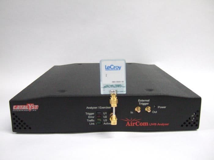
Click to zoom
Application Details
- Equipment Class
- UWB - Ultra Wideband Transmitter
- Date of Grant
- Apr 29, 2007
- Application Purpose
- Original Equipment
- Date of Application
- Mar 26, 2007
- Equipment Note
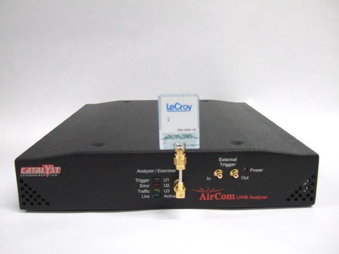
- AirCom UWB Analyzer
- Frequency Range
- 3100.00000000 - 4800.00000000
- Company
- LeCroy Corporation
- Country
- United States
Documents & Files
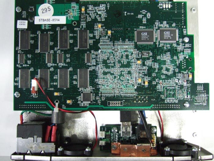
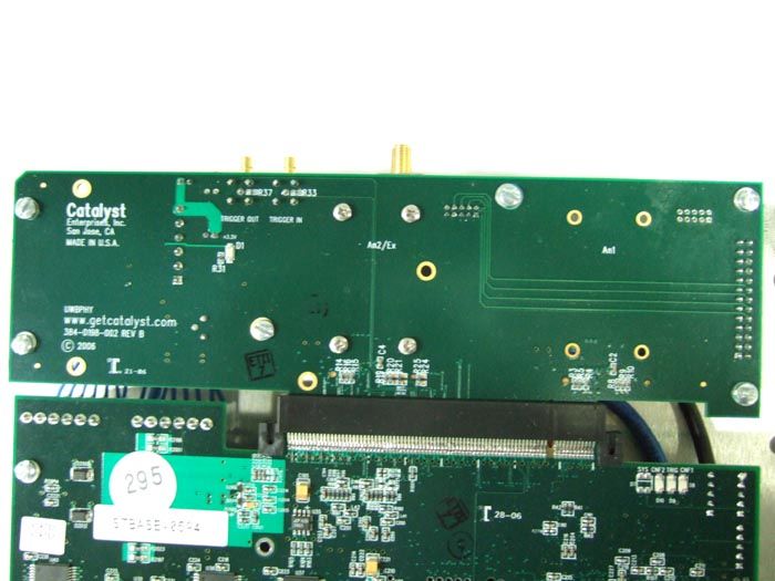
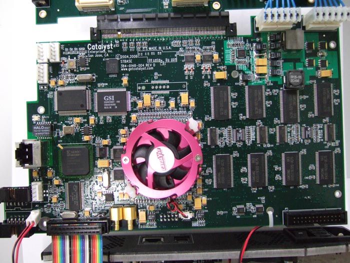
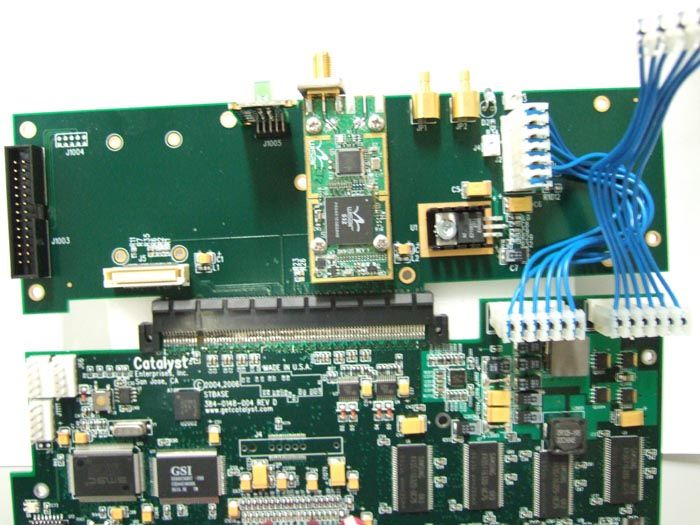
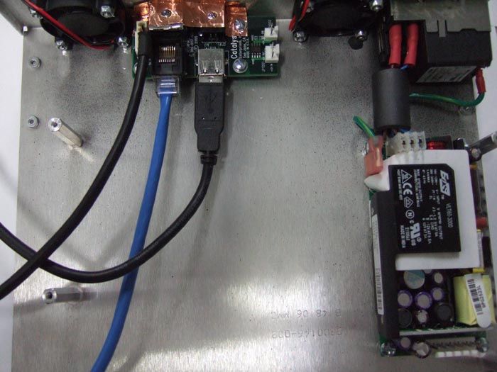
Document Text
Text extracted from the exhibit documents filed with the FCC. Open a document above to read the original.
Users Manual
March 2007 P/N 400-0103-001 User’s Manual Version 1.22 Catalyst Enterprises Inc.Copyright ii Trademarks and Servicemarks AirCom is a trademark of LeCroy Corporation. Universal Serial Bus and On-The-Go are registered trademarks of USB-IF. Microsoft and Windows are registered trademarks of Microsoft Corporation. Intel and Pentium are registered trademarks of Intel Corporation. AMD Duron and AMD Athlon are trademarks of Advanced Micro Devices, Inc. All other trademarks and registered trademarks are property of their respective owners. Disclaimer THE SPECIFICATIONS AND INFORMATION REGARDING THE PRODUCTS IN THIS MANUAL ARE SUBJECT TO CHANGE WITHOUT NOTICE. ALL INFORMATION, EXAMPLES AND RECOMMENDATIONS IN THIS MANUAL ARE BELIEVED TO BE ACCURATE BUT ARE REPRESENTED WITHOUT WARRANTY OF ANY KIND, EXPRESS OR IMPLIED. USERS ARE FULLY RESPONSIBLE FOR THEIR APPLICATION OF ANY PRODUCTS. THE SOFTWARE LICENSE AND LIMITED WARRANTY FOR THE ACCOMPANYING PRODUCT ARE SET FORTH IN INFORMATION THAT SHIPPED WITH THE PRODUCT AND ARE INCORPORATED HEREIN BY THIS REFERENCE. IF YOU ARE UNABLE TO LOCATE THE SOFTWARE LICENSE OR LIMITED WARRANTY, CONTACT LECROY CORPORATION FOR A COPY. Copyright Copyright © 2003-2007, LeCroy Corporation; All rights reserved. This document may be printed and reproduced without additional permission, but all copies should contain this copyright notice. WEEE Program This electronic product is subject to disposal and recycling regulations that var y b y country and region. Man y countries prohibit the disposal of waste electronic equipment in standard waste receptacles. For more information about proper disposal and recycling of your Catalyst product, please visit www.getcatalyst.com/recycle. CopyrightCatalyst Enterprises, Inc. iii FCC Conformance Statement Compliance with 47 CFR 15.519 (a)(1) This device complied with Part 15 of the FCC Rules. Operation is subject to the following two conditions: (1) This device may not cause harmful interference, and (2) this device must accept any interference received, including inter- ference that may cause undesired operation. FCC Rule 47 CFR 15.519 (a)(1) states that “A UWB device operating under the provisions of this section shall trans- mit only when it is sending information to an associated receiver. The UWB intentional radiator shall cease transmis- sion within 10 seconds unless it receives an acknowledgement from the associated receiver that its transmission is being received. An acknowledgement of reception must continue to be received by the UWB intentional radiator at least every 10 seconds or the UWB device must cease transmitting. “ This equipment may only be operated indoors. Operation outdoors is in violation of 47 U.S.C. 301 and could subject the operator to serious legal penalties. Note: This device must be installed in a location that is not accessible to the general public. Install the device so that the antenna is more than 20 cm from unsuspecting personnel. Failure to install this device as described will result in a failure to comply with FCC rules for RF exposure and is discouraged. Only antennas approved with the device may be used. This device may not be co-located with other transmitters without further approval by the FCC. Caution: Changes or modifications not expressly approved by the party responsible for compliance could void the operator’s authority to operate the equipment. Catalyst Enterprises Inc.Copyright iv Catalyst Enterprises, Inc. v Table of Contents Introduction - - - - - - - - - - - - - - - - - - - - - - - - - - - - - - - - - - - - - - - - - - - - 1 What’s In this Manual - - - - - - - - - - - - - - - - - - - - - - - - - - - - - - - - - - - - - - - - - - - 1 Analyzer Overview - - - - - - - - - - - - - - - - - - - - - - - - - - - - - - - - - - - - - - - - - - - - - 1 Interface- - - - - - - - - - - - - - - - - - - - - - - - - - - - - - - - - - - - - 2 LEDs - - - - - - - - - - - - - - - - - - - - - - - - - - - - - - - - - - - - - - - - - - - - - - - - - - - - - 2 Receiving Your Analyzer - - - - - - - - - - - - - - - - - - - - - - - - - - - - - - - - - - - 3 Unpacking Your Analyzer - - - - - - - - - - - - - - - - - - - - - - - - - - - - - - - - - - - - - - - - 3 Installing Your Analyzer - - - - - - - - - - - - - - - - - - - - - - - - - - - - - - - - - - - 4 Hardware Setup - - - - - - - - - - - - - - - - - - - - - - - - - - - - - - - - - - - - - - - - - - - - - - - 4 Software Installation - - - - - - - - - - - - - - - - - - - - - - - - - - - - - - - - - - - - - - - - - - - - 4 Connecting via Ethernet - - - - - - - - - - - - - - - - - - - - - - - - - - - - - 5 Connecting to a Network - - - - - - - - - - - - - - - - - - - - - - - - - - - - - - - - - - - - - - - 5 Connecting via Hub, Switch or Similar device - - - - - - - - - - - - - - - - - - - - - - - - - 6 Launching Your Analyzer - - - - - - - - - - - - - - - - - - - - - - - - - - - - - - - - - - 7 Analyzer - - - - - - - - - - - - - - - - - - - - - - - - - - - - - - - - - - - - - - - - - - - - - - - - - - - - 7 Software Launched - - - - - - - - - - - - - - - - - - - - - - - - - - - - - - - - - - - - - - - - - - - 8 Operating in Simulation Mode - - - - - - - - - - - - - - - - - - - - - - - - - - - - - - - - - - - - - 8 Protocol Analyzer Projects - - - - - - - - - - - - - - - - - - - - - - - - - - - - - - - - - - 9 Quick Start - - - - - - - - - - - - - - - - - - - - - - - - - - - - - - - - - - - - - - - - - - - - - - - - - 9 Example Projects - - - - - - - - - - - - - - - - - - - - - - - - - - - - - - - - 12 Run an Example Protocol Analyzer Project - - - - - - - - - - - - - - - - - - - 13 Saving a Trace Capture - - - - - - - - - - - - - - - - - - - - - - - - - - - - - - - - - - - - - - - 14 Protocol Analyzer Project Setup - - - - - - - - - - - - - - - - - - - - - - - - - 15 Data Capture Setup - - - - - - - - - - - - - - - - - - - - - - - - - - - - - - 16 Capture Everything - - - - - - - - - - - - - - - - - - - - - - - - - - - - - - - - - - - - - - - - 16 Pre and Post Tr…
Text truncated - open the document above for the full version.
ID Label/Location Info
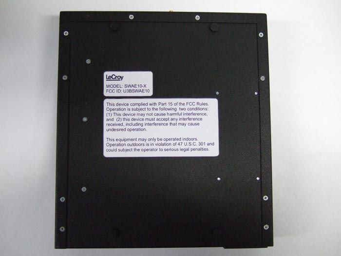
This device complied with Part 15 of the FCC Rules. Operationis subject to the following two conditions: (1) This device maynot cause harmful interference, and (2) this device must acceptany interference received, including interference that may causeundesired operation.This equipment may only be operated indoors. Operationoutdoors is in violation of 47 U.S.C. 301 and could subject theoperator to serious legal penalties. MODEL: SWAE10-XFCC ID: U6ZSWAE10 CHECKEDBY:DRAWNBY: REV.: APP’VDBY: UNLESS OTHERWISESPECIFIED, ALLDIMENSIONS AREIN mm 1:1 NOTICE: This design is the sole property of LeCroy Corporation. It contains proprietary informationand is furnished with the understanding that it is not to be used, disclosed or reproduced in anymanner without the approval of LeCroy Corporation. PART NUMBER :TITLE:SCALE: SHEET OF MFR ENGBY: TOLERANCES ARE:INCHE S = ± 0.01 in Corporation DRAWING NUMBER : DESCRIPTION DATE REV ECO # JEREMY EMS 914990 1 MARKETINGBY: A AIRCOM FCC WARNING LABEL 914990-00 TEXT COLOR: PANTONE 426CBACKGROUND COLOR: PETER LACKE VPMP00003 OR APPROVED EQUIVALENTMATERIAL: VELVET POLYCARBONATE, FINE GRAIN P35, 0.25 mm THICKADHESIVE: SCOTCH 3M 467MP OR APPROVED EQUIVALENT ® 1 27-MAR-07 PRODUCTION RELEASE PRODUCTION RELEASE 12143 A
Operational Description
Catalyst AirCom UWB Analyzer Model: SWAE10 Theory of Operation The Catalyst AirCom Ultra Wideband (UWB) Analyzer is capable of capturing and analyzing UWB traffic. The analyzer supports the following: • Capture and trigger of UWB events such as transactions and packets • Pre and post trigger pattern capture • Real time protocol error detection • Integrated frame generator to send user defined UWB frames over the air • Comprehensive statistical report. Before initiating the capture session, the user must address the following items. • Place the AirCom analyzer close to host/device and ensure the distance between the AirCom unit and host/device is less than 10 meters. • Define WiMedia channel and band group on AirCom analyzer. • Configure the AirCom analyzer software to capture the needed data. The AirCom UWB Analyzer incorporates WisAir 532 chipset and technology based on the WiMedia MB-OFDM standard. In WiMedia MB-OFDM there are 14 band groups and 30 channels. The AirCom implements only the lower three bands and seven channels of the standard with the center frequencies at 3432MHz, 3960MHz and 4488MHz. Each band is 528 MHz in bandwidth and composed of 128 OFDM tones. Each OFDM tone is 4.125 MHz in bandwidth and is QPSK modulated. The data rate is limited to 100Mbps total for uplink and downlink. The Catalyst AirCom analyzer is designed to meet the appropriate FCC part 15 rules and regulations. The AirCom analyzer configures PHY to work on a user-defined channel and capture each valid frame transmitted on this channel. The AirCom analyzer tracks Host/Device traffic and when host changes the channel, it changes capturing channel like a real device. Then AirCom extracts and shows the captured WiMedia and WUSB frames in a graphical view. The user can then search for specific pattern, filter undesired traffic or get statistical report. In ciphering connection, the AirCom could capture and decode WUSB traffic. Each device has a CDID and each Host has a CHID and each secure connection needs a CK (Connection key). The AirCom analyzer needs CDID, CHID and CK for each secure connection to decipher data transferring.
Test Report
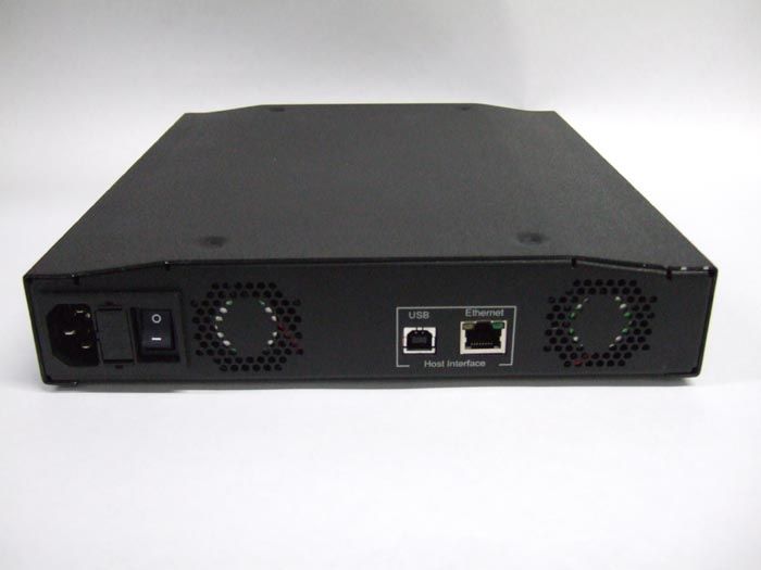
All services undertaken are subject to the following general policy. Reports are submitted for exclusive use of the client to whom they are addressed. Their significance is subject to the adequacy and representative character of the samples and to the comprehensiveness of the tests, examinations or surveys made. This report shall not be reproduced except in full, without written consent of TDK RF Systems Inc. This report must not be used to claim product endorsement by A2LA, NVLAP nor any other agency of the US Government. Compliance report of Catalyst AirCom UWB Analyzer Model: SWAE10-X Customer: LeCroy Corporation Date: March 12, 2007 TDK Report: TTS-TR-T111-110 Test performed by: TDK R&D Corporation 1101 Cypress Creek Rd Cedar Park, TX 78613 Technician Checked by Radiated 30 MHz to 40 GHz A. Medina K. Yata Conducted 150 KHz to 30 MHz A. Medina K. Yata Report A. Medina P. Carson This document contains confidential information and cannot be disclosed outside of LeCroy or any affiliated company in whole or in part without the express written permission of TDK RF Systems Inc. TTS-TR-T111-110 2 1. Executive Summary An EMC evaluation to determine compliance of the Catalyst AirCom UWB Analyzer Model: SWAE10-X with requirements of FCC 47 CFR Part 15, Subpart F Section 15.517 was conducted. All references are to the most current version of the Code of Federal Regulations 47 that is currently in effect. In accordance with §2.1033, the following data is presented in support of the Certification of the WUSB HUB. The client should retain a copy of this document on file for at least 5 years after the manufacturing of the product has been discontinued. Test Description FCC 47 CFR Section Compliance Operational Limitations 15.517(a) The client has been notified of these limitations. In normal operating mode the transmitter will only send data when associated with a receiver. See section 5 for detail UWB Bandwidth 15.517(b) Yes Radiated Emissions 15.517(c), 15.209 Yes Radiated Emissions in GPS Bands 15.517(d) Yes Peak Emissions within a 50 MHz Bandwidth 15.517(e) Yes Labelling Requirements 15.517(f) Yes Report prepared by Approved by Armando Medina Kunio Yata March 12, 2007 March 26, 2007 Page 3 of 50 2. Task Description 2.1. Scope Reference FCC ET Docket No. 98-153, FCC 02-48 First R&O; FCC 47 CFR, Part 15, Subpart A; FCC 47 CFR, Part 15, Subpart B; FCC 47 CFR, Part 15, Subpart C; FCC 47 CFR, Part 15, Subpart F FCC ET Docket No. 04-352, Petition for Waiver of the Part 15 UWB Regulations Filed by MBOA-SIG (Adopted: March 10, 2005) Title Revision of Part 15 of the Commission’s Rules Regarding Ultra-Wideband Transmissions Systems; Code of Federal Regulations, Part 15 Subpart A: General Code of Federal Regulations, Part 15 Subpart B: Unintentional Radiators Code of Federal Regulations, Part 15 Subpart C: Intentional Radiators Code of Federal Regulations, Part 15 Subpart F: Ultra- Wideband Operation Purpose of Test To gain FCC Certification Authorization for technical requirements for Indoor UWB Systems operating between 3.1 GHz and 10.6 GHz. Test Procedures The tests were conducted in accordance with the following documents: FCC ET Docket 98-153, FCC 02-48 First R&O ANSI C63.4: 2003: Methods of Measurement of Radio-Noise Emissions from Low-Voltage Electrical and Electronic Equipment in the Range of 9 kHz to 40 GHz FCC Code of Federal Regulations 47, Part 15 Subpart A: General FCC ET Docket No. 04-352, Petition for Waiver of the Part 15 UWB Regulations Filed by MBOA-SIG (Adopted: March 10, 2005) General Procedures FCC Code of Federal Regulations 47, Part 2 Frequency Allocations and Radio Treaty Matter: General Rules and Regulations Classification of EUT Indoor Ultra-Wideband System Page 4 of 50 2.2. Related Submittal(s)/Grant(s) None 2.3. Test Plan Reference Publication Year Title FCC 47 CFR, Part 15, Subpart A 10/2004 Code of Federal Regulations, Part 15 Subpart A: General FCC 47 CFR, Part 15, Subpart B 10/2004 Code of Federal Regulations, Part 15 Subpart B: Unintentional Radiators FCC 47 CFR, Part 15, Subpart C 10/2004 Code of Federal Regulations, Part 15 Subpart C: Intentional Radiators FCC 47 CFR, Part 15, Subpart F 10/2004 Code of Federal Regulations, Part 15 Subpart F: Ultra-Wideband Operation FCC ET Docket 98-153, FCC 02-48 First R&O 04/2002 Revision of Part 15 of the Commission’s Rules Regarding Ultra- Wideband Transmissions Systems: First Report & Order ANSI C63.4 01/2004 Methods of Measurement of Radio- Noise Emissions from Low-Voltage Electrical and Electronic Equipment in the Range of 9 kHz to 40 GHz FCC ET Docket No. 04- 352 3/2005 Petition for Waiver of the Part 15 UWB Regulations Filed by MBOA-SIG 2.4. Client Information APPLICANT Name: LeCroy Corporation Address: 700 Chestnut Ridge Road, Chestnut Ridge, NY 10977 Contact Person: Ravi Kalyandrug MANUFACTURER Name: Catalyst Enterprises Address: 710 Lakeway Drive Suite 135, Sunnyvale, CA 94085 Contact Person: Micky Romm Page 5 of 50 2.5. 2.5 Equipment Under Test (EUT) The following information (with the exception of the date information) has been supplied by the applicant. The test results in this report pertain only to the item tested. General Brand Name Catalyst Product Name AirCom UWB Analyzer Model Name or Number SWAE10-X Serial Number AIRCOM-0110 Type of Equipment UWB Transmitter Input Power Supply Type Public utility AC power Classification Indoor Ultra-Wideband System Technical Power Supply Requirements AC mains, 100 – 240 Vac, 50 – 60 Hz RF Output Rating -42 dBm EIRP @ 3 meters Operating Frequency Range 3100 MHz to 4800 MHz RF Output Impedance 50 Ω Channel Spacing N/A Pulse Width N/A Pulse Repetition Frequency N/A 10 dB Bandwidth >500 MHz Modulation/Constellation Multiband OFDM Oscillators’ Frequencies 24MHz, 75MHz, 60MHz, 100MHz EUT Ports 120VAC, USB(1), External trigger (in & out), Ethernet Antenna Connector Type Reverse SMA Antenna Description Linear polarized planer Logistics EUT Receive Date February 23, 2007 EUT Receive Condition…
Text truncated - open the document above for the full version.
Contact Information
Applicant
Ravi Kalyandrug(Engineering QA Manager)
Technical Contact
TDK RF SolutionsArmando Medina
[email protected]5122589478
1101 Cypress Creek Rd · Cedar Park, Texas · United States
Non-Technical Contact
TDK RF SolutionsPat Carson
[email protected]2093511584
Test Firm
TDK RF Solutions, Inc.Robert Sutton
Technical Specifications
| # | Rule Parts | Frequency Range | Power Output |
|---|---|---|---|
| 1 | 15F | 3.10 GHz - 4.80 GHz | - |
Other Applications from LeCroy Corporation
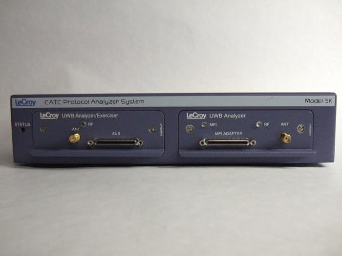
U6ZUW005
Dec 30, 2007CATC5K UWB Analyzer/Exerciser
Equipment Class
UWB - Ultra Wideband Transmitter