U7NM28AFC READER
Shen Zhen RDM Tag Master Co., Ltd.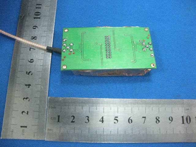
Click to zoom
Application Details
- Equipment Class
- DXX - Part 15 Low Power Communication Device Transmitter
- Date of Grant
- Jun 10, 2010
- Application Purpose
- Original Equipment
- Date of Application
- Jun 10, 2010
- Equipment Note
- AFC READER
- Frequency Range
- 13.56000000 - 13.56000000
- Country
- China
Documents & Files
Document Text
Text extracted from the exhibit documents filed with the FCC. Open a document above to read the original.
Users Manual
RDM TAG MASTER CO.,LTD ·区区路201 TEL +86-755- 61313350 Fangda Building201,Keji 12 th Rood south, High-Tech Industrial Park, Nanshan Shenzhen, China Http://www.datarfid.com [email protected] FAX+86-755- 61313357 M28 SERIAL MODULE: OEM & ODM ISO14443A/B, ISO15693, ISO11784/11785 MODULE DEVELOPMENT KIT 1 RS232 or SPI OPERATIONS The OEM & ODM ISO14443-A-B, ISO15693, ISO11784 /11785 MODULE can operate with a terminal such as computer or other controller, which can supply RS232 or SPI interface. 1.1 Electrical Interface Basically, this communication protocol does not need to be bound with any electrical interface characteristic. Typically the following types of physical link could be used: • RS232 (Point to point only) • CMOS-Logic Level (Point to point only) • SPI (Slave only) 1.2 Data Format The data format (Start Bit, Data Bits, parity, Stop Bit) is software configurable, and can be set to match the special requirement of data transmission between two communication devices. The general data format is defined as: Parameter Description Baud Rate Selective: 9600, 19200, 38400, 57600, 1152000 (It can be changed by command Send from the Host) Data Bits Fixed: 8 bits Start Bit Fixed: 1 Bits Stop Bit Selective: 1 bit. Parity None The following is the default setting (RS232): Baud Rate Data Bits Start Bit Stop Bit Parity 9600 8 1 1 None RDM TAG MASTER CO.,LTD ·区区路201 TEL +86-755- 61313350 Fangda Building201,Keji 12 th Rood south, High-Tech Industrial Park, Nanshan Shenzhen, China Http://www.datarfid.com [email protected] FAX+86-755- 61313357 2 Link Layer The communication protocol is a packet-oriented protocol - all the data exchanged between two communication devices will be based on packet format. The protocol is designed for multi-drop mode and where point-to-point mode could be treated as a special case of multi-drop mode. The data packet starts with the control character ‘STX’ and ends with ‘ETX’, which follows the 8-bit BCC checksum. Besides the checksum is used for error checking, character (byte) time-out and packet (command) time-out are used to re-synchronous the communication. 2.1 Packet Format There are two types of data packets. Command Message is the packet Send from the Host to the reader device. The Reply Message is the packet Send from the reader to the Host. Packet format for Command Message (Host to Reader) STX STATION ID DATA LENGTH CMDDATA[0..N] BCC ETX Packet format for Reply Message (Reader to Host) STX STATION ID DATA LENGTH STATUS DATA[0..N]BCC ETX RDM TAG MASTER CO.,LTD ·区区路201 TEL +86-755- 61313350 Fangda Building201,Keji 12 th Rood south, High-Tech Industrial Park, Nanshan Shenzhen, China Http://www.datarfid.com [email protected] FAX+86-755- 61313357 3 Available Commands Name Description SYSTEM COMMANDS SetAddress Program the Device Address to the reader SetBaudrate Set the reader’s communication baud rate SetSerlNum Set the reader’s Serial Number GetSerNum Get the reader’s Serial Number SetUserInfo Set the Usr Information GetUserInfo Get the User Information GetVerNum Get the reader’s firmware version number. SetPort Control status of the I/O ports. SetLED Turn On/Off the LEDs SetBuzzer Turn On/Off the Buzzer Control-workmode Control the reader to stay in active state or idle state ISO14443-A-B COMMANDS REQA ISO14443A REQUEST Anticoll ISO14443A Anti-collision Select ISO14443A Select Halt ISO14443A Halt Request_B ISO14443B REQB command Attrib_B ISO14443B ATTRIB command RDM_Rst_ Typeb Integrate the request and attrib command RDM__Typeb_Trans fer_Command ISO14443-4 transparent command Type B Card MF_Read The Read command integrates the low level commands (request, anti- collision, select, authentication, read) to achieve the reading operation with a one-step single command. MF_Write The Write command integrates the low level commands (request, anti- collision, select, authentication, write) to achieve the writing operation RDM TAG MASTER CO.,LTD ·区区路201 TEL +86-755- 61313350 Fangda Building201,Keji 12 th Rood south, High-Tech Industrial Park, Nanshan Shenzhen, China Http://www.datarfid.com [email protected] FAX+86-755- 61313357 with a one-step single command. MF_InitVal The Initialization command integrates the low level commands (request, anti-collision, select, authentication) to achieve the value block initialization with a one-step single command. MF_Decrement The Decrement command integrates the low level commands (request, anti-collision, select, authentication) to achieve the Decrement with a one-step single command. MF_HLIncrement The Increment command integrates the low level commands (request, anti-collision, select, authentication) to achieve the Increment with a one-step single command. MF_GetSnr The GetSnr command integrates the low level commands (request,anticoll,select) to achieve the select card with a one-step single command,and output the card’s Snr ISO15693 COMMANDS RDM_Inventory ISO15693 Inventory Command RDM_Read ISO15693 Read Command RDM_Write ISO15693 Write Command RDM_Lockblock ISO15693 Lock_Block Command RDM_StayQuiet ISO15693 Stay_Quiet Command RDM_Select ISO15693_Select Command RDM_Resetready ISO15693_Reset_To_Ready Command RDM_Write_Afi ISO15693_Write_AFI Command RDM_Lock_Afi ISO15693_Lock_AFI Command RDM_Write_Dsfid ISO15693_Write_DSFID Command RDM_Lock_Dsfid ISO15693_Lock_DSFID Command RDM_Get_Information ISO15693_Get_System_Information Command RDM_Get_Multiple_Block_Security ISO15693_Get_Multiple_Block_Security Command RDM TAG MASTER CO.,LTD ·区区路201 TEL +86-755- 61313350 Fangda Building201,Keji 12 th Rood south, High-Tech Industrial Park, Nanshan Shenzhen, China Http://www.datarfid.com [email protected] FAX+86-755- 61313357 RDM_15693_Transfer_CommandUsing this command may transparent ISO15693 command to The Card that it meet the ISO15693 protocol CAUTION: Changes or Modifications not expressly approved by the party responsible for compliance could void the user’s authority to operate the equipment. …
Text truncated - open the document above for the full version.
Cover Letter(s)
SHENZHEN RDM TAG MASTER CO., LTD. 4F, 25#Bld,KeZhi West Road, High-Tech Park, Nanshan Shenzhen, China May. 19,2010 Request for Modular Approval Attestation for the RFID Module(FCC ID: U7NM28) Per the FCC Public Notice DA-00-1407 for Part 15 Unlicensed Modular Transmitter approval the following information is provided: 1) “The modular transmitter must have it’s own shield.” There is shield present on the PCB, covering the section of reader. Only the RF Antenna is exposed outside the shielding. 2) “The modular transmitter must have buffered modulation/data inputs”. Input signal buffered by the IC MFRC 500. 3) The modular transmitter must have it’s own power supply regulation.” The module does not have it’s own power supply,So that the regulated power of 5V is supplied from the end product. 4) The modular transmitter must comply with the antenna requirements of Section 15.203 and 15.204(c).” The device RF section is composed of an RFID driver trip, with impedance-matching networks and RFID interrogator 4-turn coil antenna. The antenna connector is produced by RDM TAG MASTER CO., LTD.It deems to be special. 5) The modular transmitter must be tested in a stand-alone configuration, i.e., must not be inside another device during testing.” The Module was tested as a standalone device, not inside any other equipment. 6) The modular transmitter will be labeled with the FCC ID: U7NM28, and, if the FCC ID is not visible when the module is installed inside another device, then the outside of the device into which the module is installed must also display a label referring to the enclosed module. This exterior FCC ID Label will use wording, “Contains RFID Transmitter Module FCC ID: U7NM28”. 7) The modular transmitter must comply with any specific rule or operating requirements applicable to the transmitter and the manufacturer must provide adequate instructions...” The necessary explanations to comply with this requirement are contained in the manual. 8) “The modular transmitter must comply with any applicable RF exposure requirements.” The module has very low levels of RF energy that it is deemed to comply without testing of specific absorption ratio(SAR). Sincerely Yours Signature: Typed or Printed Name: Mingliang Zhu Title: Manager
External Photos
External Photo for Model: M28, M18, R18 External Photo for Model: M28, M18, R18 External Photo for Model: M28, M18, R18
ID Label/Location Info
FCC ID LABEL FCC ID:U7NM28 This device complies with Part 15 of the FCC Rules.Operation is subject to the following two conditions:1. This device may not cause harmful interference, and 2. This device must accept any interference received,including interference that may cause undesired operation. Label Location on EUT EUT Bottom View/ FCC ID Label Location
Internal Photos
Internal Photo for Model: M28, M18, R18 Internal Photo for Model: M28, M18, R18
Operational Description
Circuit Description The M28/M18/R18 module is a ISO14443 A,B and ISO15693 read/write device with a typical operating distance of 50-100mm. The reading range of the module is depending on the antenna and TAG. Also printed circuit board antennas are supported. The M28/M18/R18 combines all basic functions to access the ISO14443A,B and ISO15693 Card. Including Mifare® Smart Card, TI Card, EM Card etc. Its versatility allows a flexible and efficient application in different configurations and system devices. Because of the small size the module can be integrated easily into existing data collection applications such as portable terminals, ticketing, machines vending or access control. The 13.56MHz M28/M18/R18read/write module is a very compact device designed for fast integration into portable or stationary readers. The module was designed for simple integration. The serial TTL-interface or SPI interface can be directly connected to microprocessors and easily converted to the Interface device. The protocol can be tested using any terminal. Basic principle description: According to ISO14443A/B, ISO15693 standard, the Microprocessor(U1) and Basic frequency(13.56MHz) state(X1) will generate a specific signal, Amplifer(U2) the signal and sending out through antenna circuitry. The ISO14443A/B, ISO15693 card will get a response information for identification while it approach the transmit antenna. The receiver circuitry part will be accepting & transform it, and inform the microcomputer as well. The microcomputer based on the set program to read & write the card to fulfill the specific function. The performance of specific program setting & function is fulfilled by interface circuitry. This could be done via the smart connection between interface circuitry & computer or others smart device. Status output indicated the status during the operation, the operation process could be monitor and show the operation is correct or not. Concluded above details for M28/M18/R18, the modules with integrated function, fully compliance with ISO14443A/B,ISO15693 contactless card international standard for read & write.
Test Report
FCC PART 15.225 EMI MEASUREMENT AND TEST REPORT For SHENZHEN RDM TAG MASTER CO., LTD. 4F, 25#Bld, KeZhi West Road, High-Tech Park, Nanshan Shenzhen, China FCC ID:U7NM28 Jun. 9, 2010 This Report Concerns: Original Report Equipment Type AFC Reader Test Engineer: Eric Li Report No.: BST10050055R-3 Receive EUT Date/Test Date: May 07,2010/ May 27- Jun. 9, 2010 Reviewed By: Christina Deng Prepared By: Shenzhen BST Technology Co.,Ltd. 3F,Weames Technology Building, No. 10 Kefa Road,Science Park, Nanshan District,Shenzhen,Guangdong,China Tel: 0755-267477513 Fax: 0755-267477513 ext.826 Note: The test report is specially limited to the above company and this particular sample only. It may not be duplicated without prior written consent of Shenzhen BST Technology Co.,Ltd. This report must not be used by the client to claim product certification,approval,or endorsement by NVLAP, NIST or any agency of the US Government. The test site used to collect the data is located on the address of emitel (Shenzhen) Limited (FCC Registered Test Site Number: 746887) on Building 2, 171 Meihua Road, Futian District, Shenzhen, 518049 China The Test Site is constructed and calibrated to meet the FCC requirements. The test was performed by Eric Li from BST and supervised by Wilson Loke and Christina Deng at emitel (Shenzhen) Limited SHENZHEN RDM TAG MASTER CO., LTD. FCC ID: U7NM28 BST FCC ID REPORT : BST10050055R-3 Page 2/18 TABLE OF CONTENTS 1. GENERAL INFORMATION ....................................................................................................3 1.1. Report information ............................................................................................................3 1.2. Measurement Uncertainty .................................................................................................3 2. PRODUCT DESCRIPTION ......................................................................................................4 2.1. EUT Description ...............................................................................................................4 2.2. Block Diagram of EUT Configuration..............................................................................4 2.3. Support Equipment List ....................................................................................................4 2.4. Test Conditions .................................................................................................................4 3. FCC ID LABEL...........................................................................................................................5 4. TEST RESULTS SUMMARY ...................................................................................................6 Modifications ................................................................................................................................6 5. TEST EQUIPMENT USED .......................................................................................................7 6. CONDUCTED POWER LINE TEST .......................................................................................8 6.1. Test Equipment .................................................................................................................8 6.2. Test Procedure ..................................................................................................................8 6.3. Test Setup..........................................................................................................................8 6.4. Configurating of the EUT .................................................................................................8 6.5. EUT Operating Condition...............................................................................................10 6.6. Conducted Power line Emission Limits..........................................................................10 6.7. Conducted Power Line Test Result.................................................................................10 7. RADIATION EMISSIONS ......................................................................................................14 7.1. Test Equipment ...............................................................................................................14 7.2. Test Procedure ................................................................................................................14 7.3. Radiated Test Setup ........................................................................................................14 7.4. Radiated Emission Limit.................................................................................................15 7.5. Radiated Emission Test Result .......................................................................................15 8. FREQUENCY STABILITY.....................................................................................................17 8.1. Test Equipment ...............................................................................................................17 8.2. FCC 15.225 FREQUENCY STABILITY Limit.............................................................17 8.3. Test Result ......................................................................................................................17 9. ANTENNA REQUIREMENT .................................................................................................18 9.1. STANDARD APPLICABLE..........................................................................................18 9.2. ANTENNA CONNECTED CONSTRUCTION ............................................................18 9.3. Result ..............................................................................................................................18 SHENZHEN RDM TAG MASTER CO., LTD. FCC ID: U7NM28 BST FCC ID REPORT : BST10050055R-3 Page 3/18 1. GENERAL INFORMATION 1.1. Report information 1.1.1.This report is not a certificate of quality; it only applies…
Text truncated - open the document above for the full version.
Contact Information
Applicant
Mingliang Zhu(Manager)
Test Firm
emitel (Shenzhen) LimitedLouis Lin
Technical Specifications
| # | Rule Parts | Frequency Range | Power Output |
|---|---|---|---|
| 1 | 15C | 13.56 MHz - 13.56 MHz | - |
Other Applications from Shen Zhen RDM Tag Master Co., Ltd.
U7NRDM530
May 22, 2007DESKTOP READER
Equipment Class
DXX - Part 15 Low Power Communication Device TransmitterU7NRDM880
Apr 19, 2007RFID MODULE
Equipment Class
DXX - Part 15 Low Power Communication Device Transmitter