U7YBM-SVCBoom Chair
Lumisource, Inc.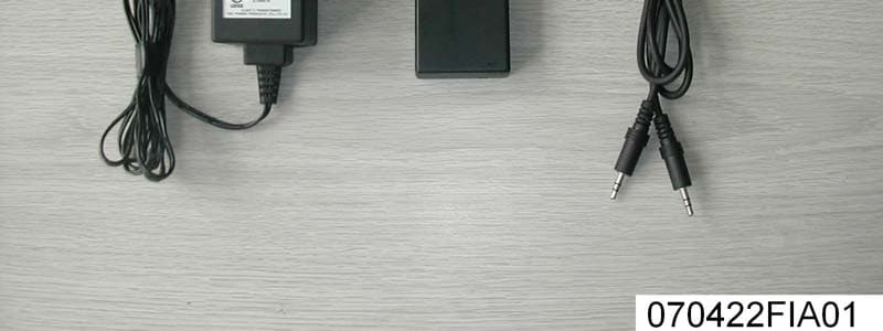
Click to zoom
Application Details
- Equipment Class
- DXX - Part 15 Low Power Communication Device Transmitter
- Date of Grant
- Jun 13, 2007
- Application Purpose
- Original Equipment
- Date of Application
- Jun 13, 2007
- Equipment Note
- Boom Chair
- Frequency Range
- 915.00000000 - 915.00000000
- Company
- Lumisource, Inc.
- Country
- United States
Documents & Files
Document Text
Text extracted from the exhibit documents filed with the FCC. Open a document above to read the original.
Users Manual
OWNER’S MANUAL ,UM3OURCE ̧ BOOMCHAIR ™ With WIRELESS Feature Multimedia Chair with Built-In SPEAKERS Congratulations! You are now the proud owner of a Wireless BOOMCHAIR™. Prepare to experience your entertainment on a whole new level. BOOMCHAIR™ allows you to HEAR the sound and FEEL the excitement. You’ll experience every crash, bang, and boom while enjoying your favorite game, music, or movie. BOOMCHAIR™ is also a great game seat built to endure the rigors of today’s gaming environment. Take a moment to review your owner’s manual before connecting your BOOMCHAIR™. Assembly and operation of the BOOMCHAIR™ is simple. If you need further assistance visit us at www.BoomChair.com or www.LumiSource.com BOOMCHAIR™, a LumiSource ® product. LumiSource, Inc. 2950 Old Higgins Road, Elk Grove Village, IL 60007 PATENTS PENDING BoomChair™, BoomChair 2.0™, BoomCube™ and BoomChair B42™ are trademarks of LumiSource, Inc. Other trademarks are properties of their respective owners. ©2006 LumiSource, Inc. All rights reserved. www.BoomChair.com & www.LumiSource.com 2 Multimedia Chair with Built-In SPEAKERS BOOMCHAIR ™ With WIRELESS Feature READ BEFORE USE • DO NOT wash or soak with water. If BOOMCHAIR™ gets wet, disconnect power immediately and do not use until completely dry. • Switch power off (0) and unplug BOOMCHAIR ™ when not in use. • Children under 5 years old should not use this product without parental supervision. • For INDOOR use only/ DO NOT expose to direct sunlight, moisture, or extreme temperatures. • DO NOT use on slippery or uneven flooring. • Excessive exposure to audio equipment at high volume may lead to hearing loss. • DO NOT open the BOOMCHAIR™ (see warning below). • DO NOT OPEN Caution: To reduce the risk of electric shock and fire, do not open the BOOMCHAIR™. There are no user serviceable parts inside. Refer to your warranty for service information FCC WARNING CAUTION: The user is cautioned that changes and modifications made to the equipment without the approval of manufacturer could void the user’s authority to operate this equipment. Notes: This equipment has been tested and found to comply with the limits for a Class B digital device, pursuant to part 15 of the FCC Rules. These limits are designed to provide reasonable protection against harmful interference in a residential installation, this equipment generates, uses and can radiate harmful interference to radio communications. However, there is no guarantee that interference will not occur in a particular installation. If this equipment does cause harmful interference to radio or television reception, which can be determined by turning the equipment off and on, the user is encouraged to try to correct the interference by one or more of the following measures: • Reorient or relocate the receiving antenna. • Increase the separation between the equipment and receiver. • Connect the equipment into an outlet on a circuit different from that to which the receiver is connected. • Consult the dealer or an experienced radio/TV technician for help. 3 #!54)/. Internal This device complies with Part 15 of the FCC rules. Operation is subject to the following two conditions: (1) This device may not cause harmful interference,and (2) This device must accept any interference received, including interference that may cause undesired operation. FCC ID: U7YBM-SVC Exposure to radio frequency energy: This device and its antenna must not be co-located or operated in conjunction with any other antenna or transmitter. To comply with FCC RF exposure requirements, only use supplied antenna. ½öÓÃÓÚÆÀ¹À¡£ °æÈ ̈ËùÓÐ (c) by Foxit Software Company, 2004 ÓÉ Foxit PDF Editor ±à¼- SET-UP GUIDE The BOOMCHAIR™ comes with the following: PARTS LIST: 1) BOOMCHAIR™ 2) AC/DC POWER SUPPLY 3a) RCA CORD (4’) (headphone jack to audio left & right channel connectors) 3b) RCA CORD (6’) (audio left & right channel connectors) 3c) RCA AUDIO COUPLER 4) RECEPTACLE 5) HOOK & LOOP FASTENER 6) MESH POCKETS (2) 7) ADJUSTABLE RECLINE STOPPERS 8) DASHBOARD CONTROL PANEL 9) ADJUSTABLE HEADREST 10) SPEAKERS 11) OPTIONAL WIRELESS TRANSMITTER 12) WIRELESS AUDIO CORD 13) WIRELESS POWER ADAPTER 4 3b 3a 1 3c 2 5 6 7 8 9 10 4 13 11 12 Power rating: 12 Volts at 1830/mA ½öÓÃÓÚÆÀ¹À¡£ °æÈ ̈ËùÓÐ (c) by Foxit Software Company, 2004 ÓÉ Foxit PDF Editor ±à¼- DASHBOARD CONTROL PANEL 5 BASS/TREBLEVOLUME POWER INPUT OUTPUT RR LL ++ (A) BASS/TREBLE CONTROL (B) POWER SWITCH / VOLUME CONTROL (C) LED POWER INDICATOR (D) HEADPHONE JACK (E) WIRELESS ON/OFF SWITCH (F) RCA AUDIO OUTPUTS (G) RCA AUDIO INPUTS Step 1: Lift seatback to the upright position. Step 2: Refer to diagram on far right for directions on securing upright position. Step 3: Insert receptacle (4) into adapter cord (2). Step 4: Plug adapter (2) into outlet. Step 5: Turn Power/Volume Control (B) clockwise. Step 6: Refer to pages 7 & 8 for connection to media devices. 6 4 Fold fabric down. Secure flap with use of hook & loop fastener. Flap maintains the seat’s upright position. STEP 2 A. B. STEP 1 2 STEP 3 BASS/TREBLEVOLUME POWER INPUT OUTPUT RR LL ++ CONNECTING TO GAME CONSOLES (WITHOUT WIRELESS FEATURE) 7 Step 1: Step 2: Plug yellow composite video cable from game console into video input of TV. (Fig. 1) Plug Red/White RCA cord from game console into RCA INPUT (F) of BoomChair™. (Fig. 2) Step 1: Step 2: Step 3: Connect Audio Coupler (3c) to Red/ White RCA cord from game console. Connect one end of RCA cord (3b) into other end of Audio Coupler (3c). Connect other end of RCA cord (3b) into RCA INPUT (F) of BoomChair™. IN Note: All game consoles are supplied with a custom connector with yellow video out and RCA red/white audio out. 3c3b GAME CONSOLETVBOOMCHAIR™ Fig. 1 Fig. 2 Cable supplied with game console Fig. 3 Alternate Connection: Connect directly from the TV Audio Out to the BoomChair™ Audio Input using the RCA audio cords provided. Note: It may be necessary to extend your BoomChair™ further away from your TV or console. Here’s how. (Fig…
Text truncated - open the document above for the full version.
Operational Description
ITEM MIN TYP MAX UNIT NOTE Supply voltage 12 V Adapter (12VDC) Current consumption 40 mA frequemcy 915 MHZ RF power 458 dBm Modele 70 KHZ 1.5V(PP) 915MHZ WIRELESS MODULE TRANSMITTER
Schematics
12345678 A B C D 87654321 D C B A Title NumberRevisionSize A2 Date:20-Mar-2007Sheet of File:E:\\\YT\FM8630926.DDBDrawn By: C1 104 +5V C7 1U 13 2 IC1 C2 1U P1 +5V P2 GND P3 CH2 P4 CH3 P5 ANT P6 ANT P7 L P8 R VK E1 47U/10V C10 1U R2 15K T1 S9014 C20 102 R12 680R T2 S9014 R14 4.7M R15 10K R17 470K R19 100K C11 1U R3 15K R13 680R T3 S9014 R16 10K R18 470K R20 100K L R +9V C5 1U RECT1 1 IN RECT1 2 IN G1 3 GND 4 OUT1 5 22 6 23 7 REF 8 25 9 26 10 27 11 OUT2 12 VCC 13 IN G2 14 IN RECT2 15 RECT2 16 IC2 R4 22K R5 22K R6 22K R7 22K R8 22K 3 2 1IC3A 5 6 7 IC3B 10 9 8IC3C 12 13 14 4 11 IC3D C6 104 +5V R9 22K R10 22K R11 22K T4 S9014 C12 1U C13 1U C8 1U/0805 C14 1U C15 1U C9 1U/0805 C16 1U C17 1U C22 2.2U C23 2.2U C18 1U C19 1U C24 2.2U C25 2.2U +5V 1.6V +5V L R GND R25 100R/1206 R26 100R/1206 +12V R27 1K D4 10V +9V C21 102 T11 S9014 T15 S9012L R64 1K E2 100U/10V R38 100K R66 470R C3 104 R22 4.7M 6 7 1 IC4A 4 5 2 IC4B +5V R67 220K +9V VK 9 8 14 12 3 IC4D LM339 +9V +5V R39 100K R53 100K VK R1 680R 1 2 3 P10 P-3 12345 P9 P-5 +12V C29 1U C46 1U D1 D2 C4 332 C28 C26 332 C32 +5V R43 8.2K R44 3.3K R45 8.2K R46 3.3K 2.5V R52 1K R54 1K R55 3.3K R56 3.3K R57 3.3K R58 3.3K T5 S9014 R29 10K R31 3.3K R33 2.2K R24 3.3K C34 223 C36 682 C38 100P T7 S9014 R30 10K R32 3.3K R35 2.2K R28 3.3K C35 223 C37 682 C39 100P 3V P11 +5V R21 C40 102 12345678 A B C D 87654321 D C B A Title NumberRevisionSize A3 Date:20-Mar-2007Sheet of File:E:\\\YT\FM8630926.DDBDrawn By: C23 104 C25 102 C27 3P C29 4P C30 3P C32 C34 1P C35 4P C36 4P C31 3P R30 47K R18 33K R55 33R R58 220R R64 100R R68 22K C46 104 VD1 D C33 5P DACKCE Y1 12.8ML C58 68P C57 8P +5V C59 2P R60 220R C7 1U R32 10K C44 104 E5 22U/6.3V TP1 PD +5V CEDACK PA2 1 PA3 2 RTCC 3 /MCLR 4 VSS 5 PB0 6 PB1 7 PB2 8 PB3 9 PB4 10 PB5 11 PB6 12 PB7 13 VDD 14 OSC2 15 OSC1 16 PA0 17 PA1 18 IC5 +5V C45 104 R84 1M R50 10K R51 10K R34 2.2K R35 2.2K C19 102 +5V R24 100K R25 100K LK RK 19K C61 2P LKRK 19K CH2 CH3 CH3CH2 FIN1 1 VDD 2 CP1 3 GND 4 LD 5 CLK 6 DATA 7 EN 8 BO 9 OSCO 10 OSCI 11 SW 12 GND 13 CP2 14 VDD 15 FIN2 16 IC7 C22 102 R61 100R L1 0.3*1.7*3T R80 4.7K VC1 5/20P C26 102 RF=500MV/50 R62 220R 60K W1 5K R83 4.7K P1 R P2 L P4 CH2 P5 CH3 P6 +5V P7 GND P8 ANT R4 10R R3 C3 T1 0R R2 R7 T2 T3T5 R1 0R R5 100R C1 2P C5 C2 2P C6 R6 C4 1PR8 R9 0R R10
Test Report
FCC ID: U7YBM-SVC Report No.: 070422FIA01 1 FCC TEST REPORT REPORT NO.: 070422FIA01 MODEL NO.: BM-SVC,BM-A44, BM-MIG, BM- AMP, BM-XTC, BM- FRG, BM-VIP, BM-VPR, BM-RAC, BM-JET, BM-UFO, BM-WiFX, BM-1-10 RECEIVED: Apr. 10, 2007 TESTED: Apr. 10 ~ May. 29, 2007 ISSUED: May. 29, 2007 APPLICANT: Lumisource, Inc. ADDRESS: 2950 OLD HIGGINS ROAD, ELK GROVE VIGGLE, IL 60007, U.S.A ISSUED BY: ADT (Shanghai) Corporation ADDRESS: 2F, Building C, No.1618, Yishan Rd., 201103, Shanghai, China This test report consists of 22 pages in total. It may be duplicated completely for legal use with the approval of the applicant. It should not be reproduced except in full, without the written approval of our laboratory. The client should not use it to claim product endorsement by A2LA or any government agencies. The test results in the report only apply to the tested sample. ADT (Shanghai) Corporation. V 1.0 FCC ID: U7YBM-SVC Report No.: 070422FIA01 2 Table of Contents 1 CERTIFICATION .......................................................................................... 3 2 SUMMARY OF TEST RESULTS .................................................................. 4 2.1 MEASUREMENT UNCERTAINTY............................................................... 4 3 GENERAL INFORMATION........................................................................... 5 3.1 GENERAL DESCRIPTION OF EUT ............................................................ 5 3.2 DESCRIPTION OF TEST MODES .............................................................. 6 3.3 GENERAL DESCRIPTION OF APPLIED STANDARDS.............................. 8 3.4 DESCRIPTION OF SUPPORT UNITS ........................................................ 9 4 EMISSION TEST........................................................................................ 10 4.1 CONDUCTED EMISSION MEASUREMENT............................................. 10 4.1.1 LIMITS OF CONDUCTED EMISSION MEASUREMENT .......................... 10 4.1.2 TEST INSTRUMENTS............................................................................... 10 4.1.3 TEST PROCEDURE.................................................................................. 10 4.1.4 TEST SETUP............................................................................................. 11 4.1.5 EUT OPERATING CONDITIONS .............................................................. 11 4.1.6 TEST RESULTS ........................................................................................ 12 4.2 RADIATED EMISSION MEASUREMENT.................................................. 13 4.2.1 LIMITS OF RADIATED EMISSION MEASUREMENT............................... 13 4.2.2 TEST INSTRUMENTS............................................................................... 14 4.2.3 TEST PROCEDURE.................................................................................. 15 4.2.4 DEVIATION FROM TEST STANDARD...................................................... 15 4.2.5 TEST SETUP............................................................................................. 16 4.2.6 EUT OPERATING CONDITIONS .............................................................. 16 4.2.7 TEST RESULTS ........................................................................................ 17 4.3 BAND EDGES MEASUREMENT .............................................................. 20 4.3.1 LIMITS OF BAND EDGES MEASUREMENT ............................................ 20 4.3.2 TEST INSTRUMENTS............................................................................... 20 4.3.3 TEST PROCEDURE.................................................................................. 20 4.3.4 DEVIATION FROM TEST STANDARD...................................................... 20 4.3.5 EUT OPERATING CONDITION................................................................. 20 4.3.6 TEST RESULTS ........................................................................................ 21 5 APPENDIX - INFORMATION ON THE TESTING LABORATORY ............. 22 FCC ID: U7YBM-SVC Report No.: 070422FIA01 3 1 CERTIFICATION PRODUCT: Boom Chair MODEL NO.: BM-SVC,BM-A44, BM-MIG, BM- AMP, BM-XTC, BM- FRG, BM-VIP, BM-VPR, BM-RAC, BM-JET, BM-UFO, BM-WiFX, BM-1-10 APPLICANT: Lumisource, Inc. TESTED: Apr. 10 ~ May. 29, 2007 TEST ITEM: ENGINEERING SAMPLE STANDARDS: 47 CFR Part 15, Subpart C (Section 15.249), ANSI C63.4-2003 The above equipment has been tested by ADT (Shanghai) Corporation, and found compliance with the requirement of the above standards. The test record, data evaluation & Equipment Under Test (EUT) configurations represented herein are true and accurate accounts of the measurements of the sample’s EMC characteristics under the conditions specified in this report. TECHNICAL ACCEPTANCE : , DATE:MAY. 29, 2007 (Vivian Hsu) Engineering Supervisor APPROVED BY : , DATE:MAY. 29, 2007 (Wallace Pan) Director of Operations FCC ID: U7YBM-SVC Report No.: 070422FIA01 4 2 SUMMARY OF TEST RESULTS The EUT has been tested according to the following specifications: APPLIED STANDARD: 47 CFR Part 15, Subpart C Standard Paragraph Test Type ResultRemark 15.207 Conducted Emission Test (Mode A1) PASS Minimum passing margin is –1.88dB at 0.310MHz Radiated Emission Test (Mode A1, Below 1GHz) PASS Minimum passing margin is –1.19dB at 457.020MHz 15.249 Radiated Emission Test (Mode A1, Above 1GHz) PASS Minimum passing margin is –3.86dB at 1371.12MHz 15.249 Band Edge Measurement PASS Meet the requirement of limit 2.1 MEASUREMENT UNCERTAINTY Where relevant, the following measurement uncertainty levels have been estimated for tests performed on the EUT as specified in CISPR 16-4: Measurement Value Conducted emissions 1.8dB Radiated emissions 3.5dB FCC ID: U7YBM-SVC Report No.: 070422FIA01 5 3 GENERAL INFORMATION 3.1 GENERAL DESCRIPTION OF EUT PRODUCT Boom Chair MODEL NO. BM-SVC,BM-A44, BM-MIG, BM- AMP, BM-XTC, BM- FRG, BM-VIP, BM-VPR, BM-RAC, BM-JET, BM-UFO, BM-WiFX, BM-1-10 POWER SUPPLY 12…
Text truncated - open the document above for the full version.
Test Setup Photos
CE (Test mode A1) RE (Test mode A1)
Contact Information
Applicant
Steve Lee
Technical Contact
ADT ShanghaiWallace Pan
[email protected]86-21-6465-9091
2F Building C, No. 1618 Yishan Rd. · Shanghai · China
Test Firm
BUREAU VERITAS ADT (Shanghai) CorporationZhaoqian YU
Technical Specifications
| # | Rule Parts | Frequency Range | Power Output |
|---|---|---|---|
| 1 | 15C | 915 MHz - 915 MHz | - |
Other Applications from Lumisource, Inc.
U7YBMSVC
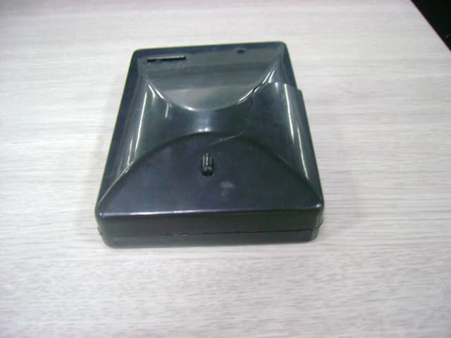
Sep 19, 2007Boomchair Wireless Transmitter
Equipment Class
DXX - Part 15 Low Power Communication Device Transmitter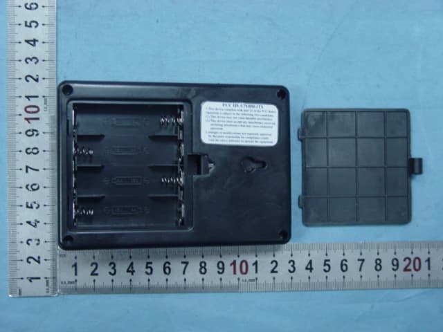
U7YBM-1TX
Sep 17, 2007Boomchair Transmitter
Equipment Class
DXX - Part 15 Low Power Communication Device Transmitter