U8ONB860Mobile Data Terminal M317
Micronet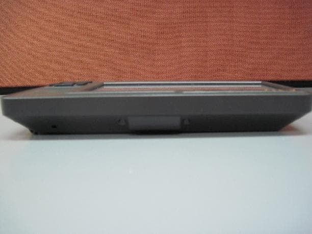
Click to zoom
Application Details
- Equipment Class
- DSS - Part 15 Spread Spectrum Transmitter
- Date of Grant
- Aug 25, 2014
- Application Purpose
- Original Equipment
- Date of Application
- Aug 25, 2014
- Equipment Note
- Mobile Data Terminal M317
- Frequency Range
- 2402.00000000 - 2480.00000000
- Company
- Micronet
- Country
- Israel
Documents & Files
Document Text
Text extracted from the exhibit documents filed with the FCC. Open a document above to read the original.
Users Manual
Revision 1.2 4 July 201 M-317 Mobile Data Terminal Hardware Guide Important Notice © 2014 Micronet Ltd. All rights reserved. Micronet Ltd. reserves the right to alter the equipment specifications and descriptions in this publication without prior notice. No part of this publication shall be deemed to be part of any contract or warranty unless specifically incorporated by reference into such contract or warranty. The information contained herein is merely descriptive in nature, and does not constitute a binding offer for the sale of the product described herein. All usage of the Micronet Ltd. logotype or trademarks is forbidden without prior written approval from Micronet Ltd. Information in this manual is subject to change without notice. Micronet maintains no liability or responsibility to any person or entity with respect to any loss or damage arising from the information contained in this book. Other company and brand products and service names are trademarks or registered trademarks of their respective holders, for example: ARM Cortex™, Microsoft™, and Microsoft™ products (Windows Embedded CE™, Compact Framework™, Microsoft Active Sync™, Visual Studio™), Google, Android, ADB, ADT, Eclipse. Please refer to Micronet’s website (http://www.micronet.co.il) for further information or contact us directly (http://www.micronet.co.il/Contact_Micronet.html). Table of Contents Rev. 1.2 M-317 Hardware Guide 3 / 50 Table of Contents Table of Contents........................................................................................................................ 3 Revision History .......................................................................................................................... 5 Safety Precautions ...................................................................................................................... 6 Introduction .............................................................................................................. 7 M-317 Platform Overview............................................................................................................. 7 M-317 Model .............................................................................................................................. 7 Display .................................................................................................................................... 8 Physical Interfaces .................................................................................................................... 8 Wireless Module (Optional) ........................................................................................................ 8 Special Protection of Application Data Feature .............................................................................. 8 Development Tool Kit .................................................................................................................. 8 Hardware ................................................................................................................................ 9 Software ................................................................................................................................. 9 Documentation ......................................................................................................................... 9 Useful Links ............................................................................................................................... 9 M-317 Platform Key Feature Specifications .................................................................................... 10 Standard Model Configuration ..................................................................................................... 10 All-In-One Model Configuration .................................................................................................... 12 Platform Accessories .................................................................................................................. 12 OEM Optional Features* (requires M-O-Q) .................................................................................... 13 M-317 Device Components ......................................................................................................... 13 M-317 Front Panel Components ................................................................................................. 13 M-317 Right Side Panel Components .......................................................................................... 15 M-317 Left Side Panel Components ............................................................................................ 16 M-317 Rear Panel Components .................................................................................................. 17 M-317 Bottom Panel Components .............................................................................................. 18 Technical and Functional Details ............................................................................. 19 Platform Core ............................................................................................................................ 19 Operating System .................................................................................................................... 19 Application Development Environment ....................................................................................... 19 Processor ............................................................................................................................... 19 RAM ....................................................................................................................................... 20 Flash Memory ......................................................................................................................... 20 Memory Card Support ...............................................................................…
Text truncated - open the document above for the full version.
Cover Letter(s)
Page1of1 Federal Communications Commission Authorization and Evaluation Division 1435 Oakland Mills Road Columbia, MD21046 Date:August 21, 2014 SUBJECT: FCC Application forU8ONB860 To Whom It May Concern: I,the undersigned, hereby attest to the fact that I will apply the Declaration of Conformity procedure to the class B computer peripheral portion of this composite device. I understand the following FCC requirements: 1. Devices subject to the DoC procedure are required to be tested to show compliance with the FCC technical regulations by a recognized accredited testing laboratory. The testing laboratory must be accredited by a Commission approved accreditation body or designated under the terms of a government-to-government Mutual Recognition Agreement (MRA). A listing of those accredited testing laboratories that have been recognized by the Commission is published on the FCC Webpage:https://apps.fcc.gov/oetcf/eas/reports/TestFirmSearch.cfm(Select the "accredited" option to search for FCC recognized accredited test firms.) 2. Test facilities located in countries, wherethe U.S. does not have an operational Telcom MRA are not recognized by the FCC to test for the DoC procedure. 3. Pt 2.1077 contains the list of information that must be included in the Declaration of Conformity, which must be supplied with each product sold.The DoC compliance info shall be included in the The info must contain thename, address, and phone number of the responsible party, which must be located within the United States.According to 2.909(c)(2), the responsible party is either the Manufactureror if the product is imported the Importer. Regards, Natan Shvarts, Quality Manager
Cover Letter(s)
Page 1 of 1 Date: July 8, 2014 To: Timco Engineering Inc. To Whom It May Concern We hereby authorize Mr. Shaike Raz of I.T.L. (Product Testing) Ltd (ITL) to sign FORM 731 on our behalf for the following application: FCC ID: U8ONB860 Thank you, Shvarts Natan Quality Manager
Cover Letter(s)
Date: July 8, 2014 To: Timco Engineering Inc. To Whom It May Concern We hereby authorize Mr. Shaike Raz of I.T.L. (Product Testing) Ltd (ITL) to act on our behalf regarding the FCC ID Certification Process for the following application: FCC ID: U8ONB860 Thank you, Shvarts Natan Quality Manager
Cover Letter(s)
Page1of1 Date:August 20, 2014 Federal Communications Commission Authorization and Evaluation Division To: Federal Communications Commission Confidentiality Request regarding application for certification of FCC ID:U8ONB860 Pursuant to Sections 0.457 and confidential treatment of information accompanying this application as outlined below: a.CONF APPENDIXM317RevisedSchem.pdf b.CONF APPENDIXM317Partlst.pdf c.CONF APPENDIXM317BlkDia.pdf The above materials contain trade secrets and proprietary information not customarily released to the public. The public disclosure of these materials may be harmful to the applicant and provide unjustified benefits to its competitors. Sincerely,
Cover Letter(s)
Date 8/21/2014 Re: FCC ID: U8ONB860 To whom it may concern, Micronet purchases the W-Fi/BT module marked JORJIN WG7311-EA shown in internal photo 6 complete with the shield already affixed to it. Micronet just attaches it to the PCB board of the M317 for which it is seeking FCC approval. Micronet does not remove the shielding nor is the shielding removable since it is soldered on. Thank you. Erez Cohen-Zedek
Operational Description
Theory of operation E.U.T: The M317 provides Original Equipment Manufacturers (OEMs) and Telematics Service Providers (TSP’s) with a rugged and versatile vehicle-centric mobile-computing platform for a variety of Mobile Resource Management (MRM) applications. The M317 platform supports the Google AndroidTM 4 operating system. The M317 offers a comprehensive development environment for independent application programming and system integration. The M317 device architecture provides a solid and cost-effective design by simplifying maintenance tasks, significantly extending product life expectancy, and lowering the total cost of ownership (TCO). The M317’s Base Model configuration contains the standard set of features and functions of the MDT (Mobile Data Terminal). There is a range of optional extensions, add-ons and accessories to enhance the M317’s capabilities, serving advanced fleet management solutions. The M317’s ruggedness is able to withstand the rough commercial automotive environment, including operation in a wide temperature range, vibrations, and shock. Using the external vehicle diagnostic and cellular communication accessory devices, the M317 platform supports the functionality of a fully integrated and standalone, fleet management solution. WiFi/BT Transmitter: WG7311 is a WiFi/ Bluetooth SiP (system in package) module that support standards: WiFi: 802.11b/g/n 2.4 GHz mode Bluetooth 1.1, 1.2, 2.0+EDR and 2.1+EDR, 3.0 and 4.0 WG7311 BT Function Digital Radio Processor (DRP) The WG7311 uses 5th-generation TI Bluetooth technology, with new features and improved radio performance. Receiver The receiver uses near-zero-IF architecture to convert the RF signal to baseband data. Received signal from the external antenna is input to a single-ended LNA (low-noise amplifier). This signal is then passed to a mixer which down-converts the signal to IF, followed by a filter and amplifier. The signal is then quantized by a sigma-delta ADC. The quantized signal is further processed to reduce the interference level. The demodulator digitally down-converts the signal to zero IF and recovers the data stream by an adaptive-decision mechanism. The demodulator includes EDR processing with state-of-the-art performance. It includes a maximum-likelihood sequence estimator (MLSE) for improved performance of basic-rate GFSK sensitivity, and adaptive equalization to enhance EDR modulation. Transmitter The transmitter is an all-digital sigma-delta PLL (ADPLL) based, with a digitally controlled oscillator (DCO) at 2.4GHz as the RF frequency clock. The modulation is achieved by directly modulating the digital PLL. The power amplifier is also digitally controlled. The transmitter uses Polar-Modulation technique. While the phase-modulated control word is being fed to the ADPLL, the amplitude-modulated controlled word is fed to the class-E amplifier to generate a BT standard compliant RF signal.
Test Report
Test Report E140190.00 Micronet Ltd. Page 1 of 75 FCC ACC M Ver 1.2 28 February 2011 DATE: 21 June 2014 I.T.L. (PRODUCT TESTING) LTD. FCC Radio Test Report for Micronet Ltd. Equipment under test: Mobile Data Terminal (MDT) M317 2.4 GHz Bluetooth Written by: _____________________________ R. Pinchuck, Documentation Approved by: _____________________________ A. Sharabi, Test Engineer Approved by: _____________________________ I. Raz, EMC Laboratory Manager This report must not be reproduced, except in full, without the written permission of I.T.L. (Product Testing) Ltd. This report relates only to items tested. Test Report E140190.00 Micronet Ltd. Page 2 of 75 FCC ACC M Ver 1.2 28 February 2011 Measurement/Technical Report for Micronet Ltd. Mobile Data Terminal (MDT) M317 FCC ID: U8ONB860 IC ID: 12186A-NB860 21 June 2014 This report concerns: Original Grant: X Class I Change: Class II Change: Equipment type: Spread Spectrum Transmitter Limits used: 47CFR15 Section 15.247 Measurement procedure used is Public Notice: DA 00-705 Filing and Measurement Guidelines for Frequency Hopping Spread Spectrum Systems and ANSI C63.4-2003. Application for Certification Applicant for this device: prepared by: (different from "prepared by") R. Pinchuck Erez Cohen-Zedek ITL (Product Testing) Ltd. Micronet Ltd. 1 Bat Sheva St. P.O.B. 11524, 27 Hametsuda St., Lod 7116002 Azor 5800171 Israel Israel e-mail [email protected] Tel: +972-3-558-4884 Fax: +972-3-558-4885 e-mail: [email protected] Test Report E140190.00 Micronet Ltd. Page 3 of 75 FCC ACC M Ver 1.2 28 February 2011 TABLE OF CONTENTS 1. GENERAL INFORMATION ------------------------------------------------------------------------------- 5 1.1 Administrative Information ................................................................................. 5 1.2 List of Accreditations ......................................................................................... 6 1.3 Product Description ........................................................................................... 7 1.4 Test Methodology .............................................................................................. 7 1.5 Test Facility ....................................................................................................... 7 1.6 Measurement Uncertainty ................................................................................. 7 2. SYSTEM TEST CONFIGURATION --------------------------------------------------------------------- 8 2.1 Justification ........................................................................................................ 8 2.2 EUT Exercise Software ..................................................................................... 8 2.3 Special Accessories .......................................................................................... 8 2.4 Equipment Modifications ................................................................................... 8 2.5 Configuration of Tested System ........................................................................ 8 3. RADIATED MEASUREMENT TEST SET-UP PHOTOS ------------------------------------------ 9 4. 6DB MINIMUM BANDWIDTH ---------------------------------------------------------------------------11 4.1 Test Specification ............................................................................................ 11 4.2 Test procedure ................................................................................................ 11 4.3 Test Results..................................................................................................... 15 4.4 Test Equipment Used. 6dB Bandwidth ........................................................... 16 5. 26DB BANDWIDTH ----------------------------------------------------------------------------------------17 5.1 Test Specification ............................................................................................ 17 5.2 Test procedure ................................................................................................ 17 5.3 Test Results..................................................................................................... 20 5.4 Test Equipment Used, 26 dB Bandwidth ........................................................ 21 6. 20DB BANDWIDTH ----------------------------------------------------------------------------------------22 6.1 Test Specification ............................................................................................ 22 6.2 Test procedure ................................................................................................ 22 6.3 Test Results..................................................................................................... 25 6.4 Test Equipment Used. ..................................................................................... 26 7. NUMBER OF HOPPING FREQUENCIES SECTION 15.247(A)(1)(III) -----------------------27 8. CHANNEL FREQUENCY SEPARATION ------------------------------------------------------------35 8.1 Test Specification ............................................................................................ 35 9. RADIATED POWER OUTPUT --------------------------------------------------------------------------39 9.1 Test Specification ............................................................................................ 39 9.2 Test procedure ................................................................................................ 39 9.3 Results Calculation .......................................................................................... 42 9.4 Test Equipment Used, Radiated Maximum Power Output ............................. 43 10. DWELL TIME ON EACH CHANNEL ------------------------------------------------------------------44 10.1 Test Specification ............................................................................................ 44 10.2 Test Procedure .........…
Text truncated - open the document above for the full version.
Contact Information
Applicant
Natan Shvarts(Quality Manager)
Test Firm
Israel Testing LaboratoriesIIan Cohen
Technical Specifications
| # | Rule Parts | Frequency Range | Power Output |
|---|---|---|---|
| 1 | 15C | 2.40 GHz - 2.48 GHz | 9.21 mW |
Other Applications from Micronet
U8ONB811
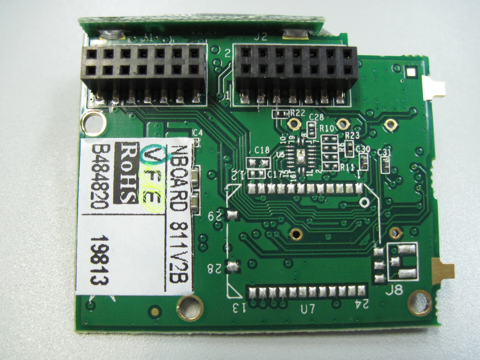
Mar 02, 2011BLUETOOTH AND WIFI MODULE
Equipment Class
DTS - Digital Transmission System
U8ONET960CE
Sep 19, 2007MOBILE DATA TERMINAL (MDT)
Equipment Class
DTS - Digital Transmission System