U99EWLAN1802.11abgn Module
Hirschmann Automation and Control GmbH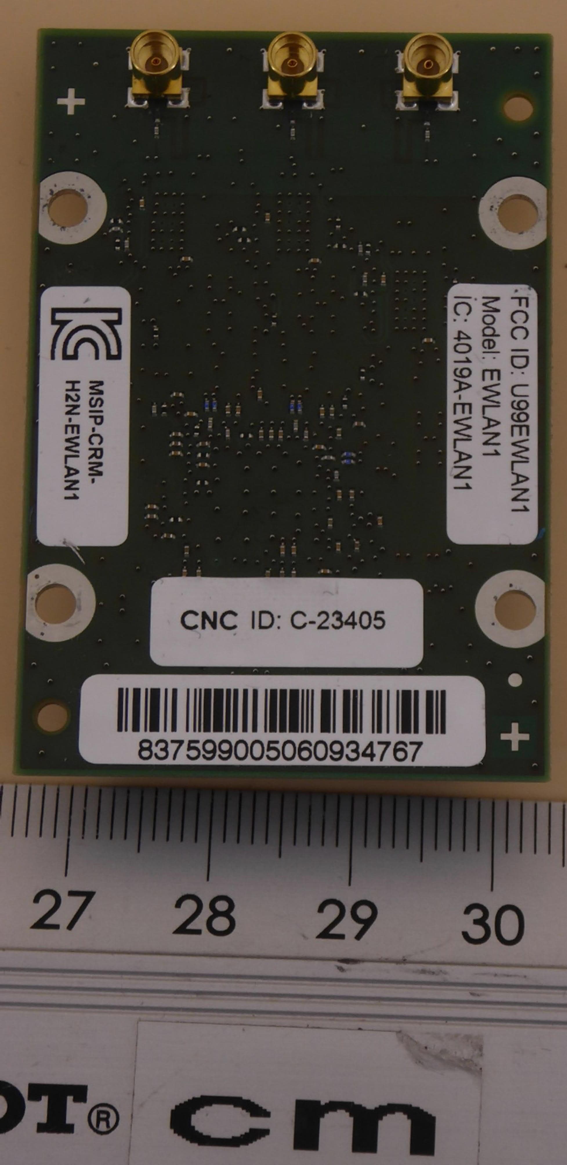
Click to zoom
Application Details
- Equipment Class
- TNB - Licensed Non-Broadcast Station Transmitter
- Date of Grant
- Aug 09, 2020
- Application Purpose
- Original Equipment
- Date of Application
- Aug 06, 2020
- Equipment Note
- 802.11abgn Module
- Frequency Range
- 4940.00000000 - 4990.00000000
- Country
- Germany
Documents & Files
Document Text
Text extracted from the exhibit documents filed with the FCC. Open a document above to read the original.
Users Manual
Installation BAT-F Release 18 07/2020 Technical support https://hirschmann-support.belden.com User Manual Installation Open Dual-Band Industrial Access-Point / Client / Access- Bridge OpenBAT-Family: BAT-F 10.07.2020 Installation BAT-F Release 18 07/2020 The naming of copyrighted trademarks in this manual, even when not specially indicated, should not be taken to mean that these names may be considered as free in the sense of the trademark and tradename protection law and hence that they may be freely used by anyone. © 2020 Hirschmann Automation and Control GmbH Manuals and software are protected by copyright. All rights reserved. The copying, reproduction, translation, conversion into any electronic medium or machine scannable form is not permitted, either in whole or in part. An exception is the preparation of a backup copy of the software for your own use. The performance features described here are binding only if they have been expressly agreed when the contract was made. This document was produced by Hirschmann Automation and Control GmbH according to the best of the company's knowledge. Hirschmann reserves the right to change the contents of this document without prior notice. Hirschmann can give no guarantee in respect of the correctness or accuracy of the information in this document. Hirschmann can accept no responsibility for damages, resulting from the use of the network components or the associated operating software. In addition, we refer to the conditions of use specified in the license contract. You can get the latest version of this manual on the Internet at the Hirschmann product site (www.hirschmann.com). Hirschmann Automation and Control GmbH Stuttgarter Str. 45-51 72654 Neckartenzlingen Germany Installation BAT-F Release 18 07/2020 3 Contents Safety instructions7 About this manual24 Key25 1Description26 1.1General description26 1.2Device name and product code27 1.3Device view31 1.4Power supply33 1.4.1 Supply voltage with the characteristic value C (24 V DC ... 48 V DC)33 1.4.2 Supply voltage with the characteristic value K (60 V DC ... 250 V DC / 110 V AC ... 230 V AC, 50 Hz ... 60 Hz)33 1.4.3 Supply voltage with the characteristic value P (Power supply only through PoE)33 1.4.4 Supply voltage with the characteristic value W (24 V DC)34 1.5Ethernet ports34 1.5.1 Gigabit combo port34 1.5.2 10/100/1000 Mbit/s twisted-pair connection (optional)35 1.5.3 Pin assignments35 1.6Connections for antennas37 1.7Display elements37 1.7.1 Meaning of the LEDs37 1.7.2 Device state38 1.7.3 Port status38 1.8Management interfaces39 1.8.1 V.24 interface (external management)39 1.8.2 USB interface41 1.9Signal contact41 1.10 Reset button41 4 Installation BAT-F Release 18 07/2020 2Installation43 2.1Checking the package contents43 2.2Installing and grounding the device43 2.2.1 Installing the device onto or on a flat surface43 2.2.2 Installing the device on a pole44 2.2.3 Grounding the device44 2.3Installing an SFP transceiver (optional)45 2.4Installing the antennas45 2.5Connecting the power supply and the signal contact lines46 2.5.1 Supply voltage with the characteristic value C (24 V DC ... 48 V DC)47 2.5.2 Supply voltage with the characteristic value K (60 V DC ... 250 V DC / 110 V AC ... 230 V AC, 50 Hz ... 60 Hz)47 2.5.3 Supply voltage with the characteristic value W (24 V DC)48 2.5.4 Signal contact49 2.6Operating the device49 2.6.1 Connecting the power supply through a 7/8" connector50 2.6.2 Connecting the power supply through PoE50 2.7Connecting data cables50 2.7.1 Gigabit combo port50 2.7.2 10/100/1000 Mbit/s twisted-pair connection (optional)51 3Making basic settings52 4First login (Password change)53 5Obtain compliance for operation in the European Union54 6Configuring the transmit power57 7Configuring the transmit power for the 4.9 GHz band59 8Maintenance and service61 Installation BAT-F Release 18 07/2020 5 9Disassembly62 9.1Removing the device62 9.2Removing an SFP transceiver (optional)62 10Technical data63 10.1 General technical data63 10.2 Dimension drawings65 10.3 Radio technology68 10.4 Roaming68 10.5 Receiving sensitivity, transmit power, and data rate of the WLAN module version EWLAN1 (Approvals 2, characteristic value M or 9)69 10.5.1 IEEE 802.11b69 10.5.2 IEEE 802.11g69 10.5.3 IEEE 802.11a70 10.5.4 IEEE 802.11n70 10.6 Receiving sensitivity, transmit power, and data rate of the WLAN module version EWLAN1 for device variants with approval for the 4.9 GHz band (Approvals 2, characteristic value P)73 10.6.1 IEEE 802.11a, Bandwidth 5 MHz73 10.6.2 IEEE 802.11a, Bandwidth 10 MHz73 10.6.3 IEEE 802.11a, Bandwidth 20 MHz74 10.7 Receiving sensitivity, transmit power, and data rate of the WLAN module version EWLAN2 for high-gain antennas (Approvals 2, characteristic value H)75 10.7.1 IEEE 802.11b75 10.7.2 IEEE 802.11g75 10.7.3 IEEE 802.11a76 10.7.4 IEEE 802.11n76 10.8 EMC and immunity78 10.9 Network range79 10.10 Power consumption/power output80 11Scope of delivery, order numbers and accessories81 6 Installation BAT-F Release 18 07/2020 12Underlying technical standards84 AFurther support86 Installation BAT-F Release 18 07/2020 7 Safety instructions General safety instructions You operate this device with electricity. Improper usage of the device entails the risk of physical injury or significant property damage. The proper and safe operation of this device depends on proper handling during transportation, proper storage and installation, and careful operation and maintenance procedures. Before connecting any cable, read this document, and the safety instructions and warnings. Operate the device with undamaged components exclusively. The device is free of any service components. In case of a damaged or malfunctioning device, turn off the supply voltage and return the device to Hirschmann for inspection. Internal fuses are triggered only in the case of a detected error in the device. In case of damage or malfunction of the device, turn off the supply voltage and return the device…
Text truncated - open the document above for the full version.
Cover Letter(s)
Long/Short-term Confidentiality Request Federal Communications Commission Date: 24 June 2020 445 12 th Street, SW Washington, DC 20554 FCC ID: U99EWLAN1 To Whom it may concerns, Pursuant to sections 0.457(d) and 0.459 of CFR 47 and to avoid premature release of sensitive information prior to marketing or release of the product to the public, we hereby request long-term confidential treatment of information accompanying this application as outlined below: ☐ Schematics ☐ Parts List ☒ Block Diagram ☐ Tune-Up Info ☒ Operational Description In addition, we hereby request the following exhibits contained in this application to be temporarily (short-term confidentilality) withheld from the public disclosure ☐ for an initial period of days ☐ until: ☒ not applicable ☐ External Photos ☐ Test Setup Photos ☐ Internal Photos ☐ User Manual The above materials contain trade secrets and proprietary information not customarily released to the public. The public disclosure of these matters might be harmful to the applicant and provide unjustified benefits to its competitors. The applicant understands that pursuant to rule 0.457(d), disclosure of this application and all accompanying documentation will not be made before the date of the GRANT for this application. If you have any questions, please feel free to contact me. Yours sincerely, Sabrina Berghahn Authorized Agent
Cover Letter(s)
Federal Communications Comission 4 September 2020 445 12 th St SW, DC 20554 Washington USA Attention: Application Examiner / Review Engineer Subject: Request for a Class II Permissive Change FCC ID: U99EWLAN1 Grant Date(s): 05/31/2016 Pursuant to CFR47 §2.1043, the Grantee hereby a request a Class II Permissive Change to add a new equipment class to the existing FCC ID as a result of a rule change. Following changes apply to the modified device: - The new FCC Part 90Y Band (4940 – 4990 MHz) will be exclusively activated by software, there is no change in hardware. - The new FCC Part 90Y Band can only be activated by the Grantee himself. - Enabling the Part 90Y Bands has no influence on the already authorized 2.4 GHz und 5 GHz frequency bands. - The different HW Version as documented in the new test report compared to the HW version in the original application is caused by adding national authorizations. - This RF Module (EWLAN1) will not be sold to any third party and will be integrated exclusively by the Grantee into his own end products. There are no further changes made to the original product. There are no changes made to the transmitter circuitry and the above listed changes result in the same RF characteristics as in the original filing - therefore the not repeated test results continue to be representative of and applicable also to this modified device. Sincerely, Sabrina Berghahn Technical Product Certification Assistant and authorized agent
External Photos
ANNEX B: EXTERNAL PHOTOGRAPHS Examiner:Paul NEUFELDReport Number: F191416E1 Date of issue: 28.05.2020Order Number: 19-111416page 1 of 2 EUT with shielding – top view ANNEX B: EXTERNAL PHOTOGRAPHS Examiner:Paul NEUFELDReport Number: F191416E1 Date of issue: 28.05.2020Order Number: 19-111416page 2 of 2 EUT – bottom view
External Photos
ANNEX B: EXTERNAL PHOTOGRAPHS Examiner:Paul NEUFELDReport Number: F191416E1 Date of issue: 28.05.2020Order Number: 19-111416page 1 of 2 EUT with shielding – top view ANNEX B: EXTERNAL PHOTOGRAPHS Examiner:Paul NEUFELDReport Number: F191416E1 Date of issue: 28.05.2020Order Number: 19-111416page 2 of 2 EUT – bottom view
ID Label/Location Info
FCC ID: U99EWLAN1 IC: 4019A-EWLAN1 Page 1 of 2 Label: FCC ID: U99EWLAN1 Model: EWLAN1 IC: 4019A-EWLAN1 Label Position: Label location Alternative location FCC ID: U99EWLAN1 IC: 4019A-EWLAN1 Page 2 of 2 Label information for host device: This device complies with Part 15 of the FCC Rules and Industry Canada licence-exempt RSS standard(s). Operation is subject to the following two conditions: (1) this device may not cause harmful interference, and (2) this device must accept any interference received, including interference that may cause undesired operation. CAN ICES-3 (B)/NMB-3(B) Contains Transmitter Module FCC ID: U99EWLAN1 IC: 4019A-EWLAN1
Internal Photos
ANNEX C: INTERNAL PHOTOGRAPHS Examiner:Paul NEUFELDReport Number: F191416E1 Date of issue: 28.05.2020Order Number: 19-111416page 1 of 1 EUT without shielding – top view
Internal Photos
ANNEX C: INTERNAL PHOTOGRAPHS Examiner:Paul NEUFELDReport Number: F191416E1 Date of issue: 28.05.2020Order Number: 19-111416page 1 of 1 EUT without shielding – top view
RF Exposure Info
Calculation: RF-Exposure for radio module Type identification: EWLAN1 FCC ID:U99EWLAN1 Subject of Investigation According the 47CFR §2.1091 the EWLAN1 module from Hirschmann Automation and Control GmbH (FCC ID: U99EWLAN1) has been defined as a device mounted in such a way, that a separation distance of at least 50 cm is normally maintained between the device and the user. The human exposure to RF emissions from such devices could be evaluated based on the MPE limits adopted by the FCC for electric and magnetic field strength and / or power density. The limits for Occupational / Controlled Exposure are given in Table 1, the limits for General Population / Uncontrolled Exposure are given in Table 2. Frequency Range [MHz] Electric Field Strength (E) [V/m] Magnetic Field Strength (H) [A/m] Power Density (S) [mW/cm²] Averaging Time |E|²,|H|² or S [min] 0.3 – 3.0 614 1.63(100)*6 3.0 – 301842/f4.89/f(900/f)*6 30 – 30061.40.1631.06 300 – 1500f/300 1500 – 100,0005 Table 1: Limits for Occupational / Controlled Exposure. Frequency Range [MHz] Electric Field Strength (E) [V/m] Magnetic Field Strength (H) [A/m] Power Density (S) [mW/cm²] Averaging Time |E|²,|H|² or S [min] 0.3 – 1.34 614 1.63(100)*30 1.34 – 30824/f2.19/f(180/f)*30 30 – 30027.50.0730.230 300 – 1500f/150030 1500 – 100,0001.0 Table 2: Limits for General Population / Uncontrolled Exposure. Note: f = frequency in MHz; * Plane – wave equivalent power density MPE evaluation In accordance to theCFR Part 47, §2.1091 S:Limit for power density according to CFR Part 47, §1.1310: 1 mW/cm 2 e.i.r.p. (4.9 GHz): 457.088 mW* (Average, including the maximum of 9 dBi antenna gain and 0.5 dB tune up range) D (4.9 GHz):Duty cycle: 100 % = 1 R:Distance in what the limit of S has to be reached: 0.5 m 4.9 GHz:ܵ= ....∗ ସ∙గ∙ோ మ ܵ →= ସହ.଼଼ௐ∙ଵ ସ∙గ∙ ( ହ ) మ = 0.0146 ௐ మ The value for the “General population / Uncontrolled Exposure” of the power density is below the limit of CFR Part 47, §1.1310. Limits and calculated results The results for EWLAN1 are given in Table 3 and based on the power measurements shown in Phoenix Testlab Reports F191416E1. BandCH f [MHz] d [cm] EIRP* [dBm] EIRP* [mW] Power Density [mW/cm²] Limit of Power Density [mW/cm²] Evaluation Result 4.9 GHz 23 496550 26.6 457.0880.01461.0Complies Table 3: Calculated results for the EWLAN1 compared to the limit for uncontrolled exposure. *The EIRP value includes 0.5 dB tune-up margin as declared by the applicant. The EWLAN1 from Hirschmann Automation and Control GmbH (FCC ID: U99EWLAN1) is in compliance with the maximum permissible exposure (MPE) limits for the Power Density given by the FCC 47CFR §1.1310 (4)(e) Table 1.
Test Report
Königswinkel 10 32825 Blomberg, Germany Phone: +49 (0) 52 35 / 95 00-0 Fax:+49 (0) 52 35 / 95 00-10 [email protected] www.phoenix-testlab.de Test Report Report Number: F191416E1 Equipment under Test (EUT): EWLAN1 WLAN module Applicant: Hirschmann Automation and Control GmbH Manufacturer: Hirschmann Automation and Control GmbH Examiner:Paul NEUFELDReport Number: F191416E1 Date of issue: 28.05.2020Order Number: 19-111416page 2 of 39 References [1] ANSI C63.26-2015, American National Standard for Compliance Testing of Transmitters Used in Licensed Radio Services. [2] FCC CFR 47 Part 90 Subpart Y, Regulations Governing Licensing and Use of Frequencies in the 4940-4990 MHz Band [3] 971168 D02 Misc Rev Approv License Devices v02r01, Radio Frequency Devices [4] 789033 D02, General U-NII Test Procedures New Rules v02r01 [5] Inquiry 300709, PSD measurement according to §90.1215 Test Result The requirements of the tests performed as shown in the overview (clause 0) were fulfilled by the equipment under test. The complete test results are presented in the following. T h i s t e s t r e p o r t i s o n l y v a l i d i n i t s o r i g i n a l f o r m . Any reproduction of its contents in extracts without written permission of the accredited test laboratory PHOENIX TESTLAB GmbH is prohibited. The test results herein refer only to the tested sample. PHOENIX TESTLAB GmbH is not responsible for any generalisations or conclusions drawn from these test results concerning further samples. Any modification of the tested samples is prohibited and leads to the invalidity of this test report. Each page necessarily contains the PHOENIX TESTLAB Logo and the TEST REPORT NUMBER. This test report is valid in hardcopy form as well as in electronic form. Test engineer:Paul NEUFELD28.05.2020 NameSignatureDate Authorized reviewer:Bernd STEINER28.05.2020 Name Signature Date Examiner:Paul NEUFELDReport Number: F191416E1 Date of issue: 28.05.2020Order Number: 19-111416page 3 of 39 ContentsPage 1Identification .......................................................................................................................... 4 1.1Applicant ............................................................................................................................................ 4 1.2Manufacturer ..................................................................................................................................... 4 1.3Test Laboratory ................................................................................................................................. 4 1.4EUT (Equipment Under Test) ............................................................................................................ 5 1.5Technical Data of Equipment ............................................................................................................ 7 1.6Dates ................................................................................................................................................. 8 2Operational States ................................................................................................................. 8 3Additional Information .......................................................................................................... 10 4Overview .............................................................................................................................. 11 5Results................................................................................................................................. 12 5.1Duty cycle ........................................................................................................................................ 12 5.2Maximum conducted output power ................................................................................................. 12 5.2.1Method of measurement ......................................................................................................... 12 5.2.2Test results ............................................................................................................................. 13 5.3Power Spectral Density ................................................................................................................... 14 5.3.1Method of measurement ......................................................................................................... 14 5.3.2Test result ............................................................................................................................... 15 5.426 dB Bandwidth / 99% Bandwidth ................................................................................................. 17 5.4.1Method of measurement ......................................................................................................... 17 5.4.2Test result ............................................................................................................................... 17 5.5Peak Excursion ............................................................................................................................... 20 5.5.1Method of measurement (Peak Excursion) ............................................................................ 20 5.5.2Test result (Peak Excursion) .................................................................................................. 21 5.5.3Method of measurement (Emission Mask L - conducted) ...................................................... 22 5.5.4Test result (Emission mask frequency within150 % of the authorized bandwidth) ................ 22 5.5.5Test result (Emission mask frequency outside 150 % of the authorized bandwidth) ............. 24 5.6Maximum unwanted emissions ....................................................................................................... 27 5.6.1Method of measurement (radiated emissions) ....................................................................... 2…
Text truncated - open the document above for the full version.
Test Setup Photos
ANNEX A: TEST SETUP PHOTOGRAPHS Examiner:Paul NEUFELDReport Number: F191416E1 Date of issue: 28.05.2020Order Number: 19-111416page 1 of 11 Test setup – conducted measurement ANNEX A: TEST SETUP PHOTOGRAPHS Examiner:Paul NEUFELDReport Number: F191416E1 Date of issue: 28.05.2020Order Number: 19-111416page 2 of 11 Test setup – radiated test in anechoic chamber (M276) ANNEX A: TEST SETUP PHOTOGRAPHS Examiner:Paul NEUFELDReport Number: F191416E1 Date of issue: 28.05.2020Order Number: 19-111416page 3 of 11 Test setup – radiated test in anechoic chamber (M276) ANNEX A: TEST SETUP PHOTOGRAPHS Examiner:Paul NEUFELDReport Number: F191416E1 Date of issue: 28.05.2020Order Number: 19-111416page 4 of 11 Test setup – radiated test in anechoic chamber (M276) ANNEX A: TEST SETUP PHOTOGRAPHS Examiner:Paul NEUFELDReport Number: F191416E1 Date of issue: 28.05.2020Order Number: 19-111416page 5 of 11 Test setup – radiated test in anechoic chamber (M276) ANNEX A: TEST SETUP PHOTOGRAPHS Examiner:Paul NEUFELDReport Number: F191416E1 Date of issue: 28.05.2020Order Number: 19-111416page 6 of 11 Test setup – radiated test in anechoic chamber (M276) ANNEX A: TEST SETUP PHOTOGRAPHS Examiner:Paul NEUFELDReport Number: F191416E1 Date of issue: 28.05.2020Order Number: 19-111416page 7 of 11 Test setup – radiated test in anechoic chamber (M276) ANNEX A: TEST SETUP PHOTOGRAPHS Examiner:Paul NEUFELDReport Number: F191416E1 Date of issue: 28.05.2020Order Number: 19-111416page 8 of 11 Test setup – radiated test in anechoic chamber (M276) ANNEX A: TEST SETUP PHOTOGRAPHS Examiner:Paul NEUFELDReport Number: F191416E1 Date of issue: 28.05.2020Order Number: 19-111416page 9 of 11 Test setup – conducted emissions on power supply lines ANNEX A: TEST SETUP PHOTOGRAPHS Examiner:Paul NEUFELDReport Number: F191416E1 Date of issue: 28.05.2020Order Number: 19-111416page 10 of 11 EUT with BAT-R host device – 3D view 1 ANNEX A: TEST SETUP PHOTOGRAPHS Examiner:Paul NEUFELDReport Number: F191416E1 Date of issue: 28.05.2020Order Number: 19-111416page 11 of 11 EUT with BAT-R host device – 3D view 2
Test Setup Photos
ANNEX A: TEST SETUP PHOTOGRAPHS Examiner:Paul NEUFELDReport Number: F191416E1 Date of issue: 28.05.2020Order Number: 19-111416page 1 of 11 Test setup – conducted measurement ANNEX A: TEST SETUP PHOTOGRAPHS Examiner:Paul NEUFELDReport Number: F191416E1 Date of issue: 28.05.2020Order Number: 19-111416page 2 of 11 Test setup – radiated test in anechoic chamber (M276) ANNEX A: TEST SETUP PHOTOGRAPHS Examiner:Paul NEUFELDReport Number: F191416E1 Date of issue: 28.05.2020Order Number: 19-111416page 3 of 11 Test setup – radiated test in anechoic chamber (M276) ANNEX A: TEST SETUP PHOTOGRAPHS Examiner:Paul NEUFELDReport Number: F191416E1 Date of issue: 28.05.2020Order Number: 19-111416page 4 of 11 Test setup – radiated test in anechoic chamber (M276) ANNEX A: TEST SETUP PHOTOGRAPHS Examiner:Paul NEUFELDReport Number: F191416E1 Date of issue: 28.05.2020Order Number: 19-111416page 5 of 11 Test setup – radiated test in anechoic chamber (M276) ANNEX A: TEST SETUP PHOTOGRAPHS Examiner:Paul NEUFELDReport Number: F191416E1 Date of issue: 28.05.2020Order Number: 19-111416page 6 of 11 Test setup – radiated test in anechoic chamber (M276) ANNEX A: TEST SETUP PHOTOGRAPHS Examiner:Paul NEUFELDReport Number: F191416E1 Date of issue: 28.05.2020Order Number: 19-111416page 7 of 11 Test setup – radiated test in anechoic chamber (M276) ANNEX A: TEST SETUP PHOTOGRAPHS Examiner:Paul NEUFELDReport Number: F191416E1 Date of issue: 28.05.2020Order Number: 19-111416page 8 of 11 Test setup – radiated test in anechoic chamber (M276) ANNEX A: TEST SETUP PHOTOGRAPHS Examiner:Paul NEUFELDReport Number: F191416E1 Date of issue: 28.05.2020Order Number: 19-111416page 9 of 11 Test setup – conducted emissions on power supply lines ANNEX A: TEST SETUP PHOTOGRAPHS Examiner:Paul NEUFELDReport Number: F191416E1 Date of issue: 28.05.2020Order Number: 19-111416page 10 of 11 EUT with BAT-R host device – 3D view 1 ANNEX A: TEST SETUP PHOTOGRAPHS Examiner:Paul NEUFELDReport Number: F191416E1 Date of issue: 28.05.2020Order Number: 19-111416page 11 of 11 EUT with BAT-R host device – 3D view 2
Contact Information
Applicant
Martin Burkhardt
Test Firm
PHOENIX TESTLAB GmbHHolger Bentje
Technical Specifications
| # | Rule Parts | Frequency Range | Power Output | Emission | Tolerance |
|---|---|---|---|---|---|
| 1 | 90Y | 4.94 GHz - 4.99 GHz | 51.30 mW | 17M2F1D | 5.2000000000 % |
Other Applications from Hirschmann Automation and Control GmbH
U99EWLAN2
Jan 27, 2014802.11abgn Module
Equipment Class
DTS - Digital Transmission System