U9YHS6618AWireless USB Dongle
Alereon, Inc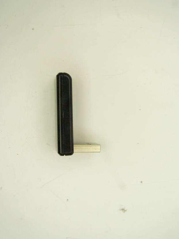
Click to zoom
Application Details
- Equipment Class
- UWB - Ultra Wideband Transmitter
- Date of Grant
- Aug 26, 2012
- Application Purpose
- Original Equipment
- Date of Application
- Aug 06, 2012
- Equipment Note
- Wireless USB Dongle
- Frequency Range
- 7400.00000000 - 8962.00000000
- Company
- Alereon, Inc
- Country
- United States
Documents & Files
Document Text
Text extracted from the exhibit documents filed with the FCC. Open a document above to read the original.
Users Manual
Alereon HS6618A User Guide p.1/2 Alereon HS6618AA USB Dongle Users Guide OVERVIEW This document describes the usage of the HS6618A. The HS6618A is used as a Wireless USB Host Adapter. The HS6618A allows the user to connect various Wireless USB devices to a PC or other device with USB capabilities. INSTALLATION The HS6618A can be configured to operate in two modes. First, it can operate in driverless mode which requires no drivers be installed. The installation process for this mode of operation is to insert the HS6618A into an available USB port. The second option is Host Wire Adapter (HWA) mode. This mode requires installation of the Wireless USB Manager. 1.1 Installing Wireless USB Manager for HWA mode Alereon provides MSI based installers. Each installer is designated by the platform it supports in the filename. For example, • Setup_wusb_X86_XXXX.msi - indicates that this MSI is for 32 bit systems • Setup_wusb_X64_XXXX.mdi - indicates that this MSI is for 64 bit systems You can launch the installation process by double clicking the MSI package. Please follow the following steps in order to install Alereon's Wireless USB Manager. Note: Wireless USB Manager has a dependency on Microsoft .NET 2.0. you will have to install this software manually before going through the setup or connect the PC to the internet and the setup will automatically download this dependency from the internet. •Use the installation program to install the Wireless USB Manager Figure 2. Wireless USB Installer Alereon HS6618A User Guide p.2/2 1.2 FCC requirements for information to the user. This device complies with part 15 of the FCC Rules. Operation is subject to the following two conditions: (1) this device may not cause harmful interference, and (2) this device must accept any interference received, including interference that may cause undesired operation. This device is authorized under 47 CFR 15.519 (the FCC Rules and Regulations). The operation of this device is subject to the following restriction: This UWB device shall transmit only when it is sending information to an associated receiver. This UWB device shall cease transmission within 10 seconds unless it receives an acknowledgement from the associated receiver that its transmission is being received. An acknowledgement of reception must continue to be received by the transmitting device at least every 10 seconds of operation or the UWB device must cease transmitting. Warning: Changes or modifications to this device not expressly approved by Alereon could void the users authority to operate the device under the FCC Equipment Authorization The users manual or instruction manual shall contain this information about interference control: Electromagnetic Interference (EMI) is any signal or emission, radiated in free space or conducted along power or signal leads, that endangers the function of radio navigation or other safety service (the telephone and cellphones are considered to be safety services) or seriously degrades, obstructs or repeatedly interrupts a licensed radio communications service. Radio communications services include but are not limited to: AM/FM commercial broadcast, television, cellular services, radar, air traffic control, pager and personal communications services (PCS). These licensed services, along with unintentional radiators such as digital devices, including computer systems, contribute to the electromagnetic environment. Electromagnetic Compatibility (EMC) is the ability of items of electronic equipment to function properly together in the electromagnetic environment. While this device has been designed and determined to be compliant with regulatory agency limits for EMI, there is no guarantee that interference will not occur in a particular installation. If this device does cause interference with radio communications services, which can be determined by turning the device on and off, you are encouraged to try to correct the interference by one or more of the following measures: •Re orient the receiving antenna •Relocate the device with respect to the victim receiver •Move the device away from the victim receiver •Plug the device host into a different power outlet than the victim receiver so that the device system and receiver are on separate branch circuits If necessary, consult your system service representative or an experienced radio/television technician for additional help in resolving interference.
Cover Letter(s)
[7600 N. Capital of Texas Hwy] [Building C] [Suite 200] [Austin, TX 78731] ph [512-345-4200] fx [512-345-4201] July 17, 2012 Chief, Authorizations Branch Federal Communications Commission 7435 Oakland Mills Road Columbia, MD 21046 Subject: Request for confidentiality. FCC ID: U9YHS6618A To Whom It May Concern: Pursuant to DA 04-1705 of the Commission’s pubic notice, in order to comply with the marketing regulations in 47CFR §2.803 and the importation rules in 47 CFR §2.1204, while ensuring that business sensitive information remains confidential until the actual marketing of newly authorized devices. Alereon requests the commission to grant short-term confidentiality request on the following attachments. 1. Internal Photographs 2. External Photographs Pursuant to Sections 0.457 and 0.459 of the Commission’s Rules, Alereon Hereby requests the commission to grant permanent confidentiality for information accompanying this Application As outlined below: 1. Block Diagram 2. Schematics 3. Bill of Materials The above materials contain trade secrets and proprietary information not customarily released to the public. The public disclosure of these materials may be harmful to the applicant and provide unjustified benefits to its competitors. The applicant understands that pursuant to Section 0.457 of the Rules, public disclosure of this application and accompanying documentation not subject to confidentiality will not be made before the date of the Grant for this application. Should you require any further information, please contact the undersigned. Thank you for your consideration in this matter. Sr. Principal RF Engineer Applicant :Alereon, Inc. Address :7600-C Suite 200 Capitol of Texas Highway Austin TX, 78731 E-mail [email protected]: Telephone 512 418 2137
Cover Letter(s)
[7600 N. Capital of Texas Hwy] [Building C] [Suite 200] [Austin, TX 78731] ph [512-345-4200] fx [512-345-4201] p. 1/2 July 17, 2012 Chief, Authorizations Branch Federal Communications Commission 7435 Oakland Mills Road Columbia, MD 21046 Subject: Request for unlicensed Modular Transmitter Approval: U9YHS6618A. Reference: FCC 07-56A1 47 CFR 15.212 To Whom It May Concern: Alereon, Inc. hereby requests FCC Equipment Authorization as a Singular Modular Transmitter of the Alereon, Inc. Model HS6618A UWB Dongle, FCC ID: U9YHS6618A. Alereon, Inc. intends to manufacture this device and market it under several brand names and brand I.D.s as a computer modular component. This letter addresses the information required by points one through eight of 47 CFR 15.212. 1. The modular transmitter must have its own RF shielding. All shielding necessary for normal operation is accomplished by the multi-layer construction of the printed wiring board which incorporates multiple ground layers in its construction. As this transmitter is designed to operate stand-alone in its own enclosure, connected to an industry-standard USB 2.0 interface, no additional shielding is incorporated to minimize coupling such as may occur if the module were incorporated into another unit. 2. The modular transmitter must have buffered modulation/data inputs. The Alereon HS6618A receives data via the industry-standard USB 2.0 interface. This USB interface is implemented within the AL6301 integrated circuit as may be seen on sheet two of the schematic diagram included in the filing for FCC Equipment Authorization. The USB interface limits the data rate to those defined by the USB standard. 3. The modular transmitter must have its own power supply regulation. The Alereon HS6618A receives power from the host system via the USB 2.0 interface. The +5.0 Volt source from the host system is regulated on the module to power a +3.3V domain and the main +1.2V digital subsystem domain. The +3.3V domain is also regulated on the module to produce two additional power domains required by the module circuitry; +2.4V and +1.2V. The power regulation topology may be seen on sheet five of the schematic diagram included in the filing for FCC Equipment Authorization. 4. The modular transmitter antenna must comply with the antenna and transmission system requirements of sections 15.203, 15.204(b) and 15.204(c). The antenna of the HS6618A is microstrip patch type BWT design UWBH-002. The antenna is etched onto the HS6618A PCB and it is entirely within the product housing and connects to the AL5100 RF transceiver device on the PCB, this connection is entirely within the plastic enclosure. The antenna is not removable by the user. The compliance test report [7600 N. Capital of Texas Hwy] [Building C] [Suite 200] [Austin, TX 78731] ph [512-345-4200] fx [512-345-4201] p. 2/2 contains data taken with this antenna type demonstrating compliance with FCC requirements. 5. The modular transmitter must be tested in a stand-alone configuration. As described in the test report included in the filing for FCC Equipment Authorization, the HS6618A UWB Module plus antenna was tested without a plastic housing, connected to the USB port of a P.C. as it is intended to operate. The HS6618A is designed with an industry standard USB 2.0 Type-A connector as its electrical and mechanical interface to the host system. This connector defines the deployment of the module which is intended to be directly connected to the host system via the USB interface. 6. The modular transmitter must be equipped with either a permanently affixed label or must be capable of electronically displaying its FCC identification number. The Alereon HS6618A is intended to be placed within a plastic enclosure unique to the brand I.D. under which it is being marketed. The prescribed label with the FCC Identifier will be applied to the outside of the housing. An example of the label which will be used is included in the filing for FCC Equipment Authorization. 7. The modular transmitter must comply with any specific rule or operating requirements applicable to the transmitter. Part 15.519 of the FCC rules and Regulations requires that a UWB transmitter shall transmit only when it is sending information to an associated receiver. That rules part also requires that the UWB intentional radiator shall cease transmission within 10 seconds unless it receives an acknowledgement from the associated receiver that its transmission is being received. An acknowledgment of reception must continue to be received by the UWB intentional radiator at least every 10 seconds or the UWB device must cease transmitting. This requirement is met by design and is implemented by the firmware encoded into the device. 8. The modular transmitter must comply with any applicable RF exposure requirements in its final configuration. There are no RF exposure requirements for UWB devices operating under subpart F of the FCC Rules and Regulations. David M. Dickson Sr. Principal Engineer Alereon, Inc.
ID Label/Location Info
Drawing g of label whhich will be applied to the Alereonn HS6618AA, FCC ID: U9YHS66118A The pro d • M • M • F Incorpor housing Loca duct housin Manufacture Model Numb FCC ID: rated into th . ation of lab ng of the HS er ber he product bel on Alere S6618A wil label which eon HS6618 l have the s h will be pla 8A USB Do same inform aced on the ongle PCBA mation: outside of A the producct
Operational Description
Alereon Confidential Page 1 7/17/2012 Theory of operation; Alereon HS6618A USB Dongle. 1.0 Discussion of the Functional Architecture and chipset Functions. The Alereon HS6618A is a UWB radio device with a USB interface to the host computer. This device is intended to provide a short-range wireless USB connection for computers and peripheral units equipped with a USB 2.0 3 interface. The HS6618A is powered entirely from the USB connector of the host system to which it is attached. The HS6618A operates in the frequency band defined in the FCC rules and Regulations for UWB devices. Specifically, it operates between the frequencies of 3.168 and 8.976 GHz per the industry-defined WiMedia 1.1 specification 1 . The HS6618A is comprised of two integrated circuit devices and supporting circuitry for firmware, filtering, interface and power conditioning. The HS6618A has a permanently attached antenna internal to the product housing. The schematic diagram shows a connector, Murata MM8030- 2600RK0, in the RF path. This connector, is not accessible from outside of the unit housing, it is used for factory test of the devices during production. Following the factory test connector is a Diplexer type bandpass filter having two sections; The LB section has a passband from 3.1 GHz to 4.752 GHz, the HB section has a passband from 6.336GHz to 8.976GHz. This filter provides suppression of unwanted out of band transmitter emissions and receiver interference rejection in the 2.4 GHz and 5.1 GHz bands. The AL5100 RF Transceiver generates the system reference frequency from a 44 MHz crystal resonator. The 44 MHz reference frequency is multiplied to 16.896 GHz internally in the AL5100 by a PLL multiplier. From this frequency the local oscillator frequencies for band frequencies for both transmit and receive modes are derived internally within the AL5100 by direct synthesis. The local oscillator frequencies are as listed as Fmid per the following table. Figure 1. L.O. Frequency Table In addition to the band frequencies, a 1056 MHz clock for ADCs and DACs within the AL6301 Baseband Processor/MAC is generated by the AL5100 RF Transceiver. The interface between the AL5100 RF Transceiver and the AL6301 Baseband Processor/MAC consists of the analog RX-I and –Q signals and the analog TX–I and –Q signals all of which are baseband, having 2 MHz to 264 MHz frequency band. The interface also includes a 1056 MHz Alereon Confidential Page 2 7/17/2012 clock signal and CMOS logic-level control signals which are used by the MAC within the AL6301 to control the band frequency and mode of operation; TX, RX or Idle (TX and TX powered-down). The AL6301 design is based on the WiMedia MAC-PHY Interface Specification 2.0 2 . The AL6301 implements the digital functionality for the UWB radio consisting of the following functions: RX Baseband Signal ADC. Receive digital signal Processing. Data Encryption and Decryption. Transmit Digital Signal Processing. TX Baseband Signal DAC. Digital interface to AL5100 for control. ARM processor implementation of the MAC. USB 2.0 PHY, interface to host system. The AL6301 and its associated firmware memory, and power filtering and conditioning circuits perform no function other than support of the UWB radio function. Among the radio support functions, the AL6301 MAC implements the FCC-required function of verifying that transmissions are acknowledged by the device-side unit at 10 second intervals for the entire time that the UWB link is active. If the 10-second timeout test fails, the AL6301 MAC firmware embedded within the AL6301 will cause transmissions to cease. 2.0 Discussion of Channelization. The HS6618A implements the spectrum and channelization plan described by the WiMedia specification 1.1. While the basic AL5100 / AL6301 chipset is capable of implementing a UWB radio capable of operation on every WiMedia defined band group and channel, operation of the HS6618A is limited to those WiMedia channels which are implemented within band group 1 (3.168 – 4,752 GHz), band group 3 (6.336 – 7.920 GHZ) and band group 6 (7.392 – 8.976 GHz). EdgesCenter 136 3168 1 3432 3696 2 3960 4224 3 4488 4752 6336 7 6600 6864 8 7128 7392 9 7656 7920 10 8184 8448 11 8712 8976 BG Band Frequency Map Figure 2. Band Group Frequency Table Alereon Confidential Page 3 7/17/2012 Band group 2 (4.752 – 6.336 GHz) is not used because this band group coincides with IEEE 802.11 wireless LAN operations. Concerns about mutual interference between radios co-located within the same host system have driven this consideration. The upper three sub bands of the WiMedia spectrum plan (8.976 – 10.560 GHz) which are a portion of band group 4 and band group 5 are not implemented due to technology limitations in the filter and antennas. Within the implemented band groups, channels are enabled or disabled according to the regulatory domain for which the specific device is intended. The enabled channels are set by a channel map table embedded within the firmware of the MAC. This table is programmed with the enabled channels during manufacture by the Alereon factory test station software at the same time that the device firmware image is loaded. The channel map is not accessible to the end user. The interface between the HS6618A USB dongle and the host system is via the industry-defined USB 2.0. The HS6621 is powered by 5.0V DC from the host system. Power conditioners on the HS6621 generate the various voltages required by the integrated circuits. References. 1. MultiBand OFDM Physical Layer Specification 1.1. 2. MAC-PHY Interface Specification 1.0. 3. Universal Serial Buss Specification 2.0.
RF Exposure Info
UWB ANTENNA APPROVAL SHEET BN42-xxxxxx 1 of 18 COMPANY CONFIDENTIAL UWB ANTENNA APPROVAL SHEET Proprietary Information All information contained in this document is confidential and proprietary toHanshin IT. No license, expressed or implied, under any patent, copyright or trade secret right is granted or implied by the conveyance of this document. No part of this document may be reproduced, transmitted, transcribed, stored in a retrieval system, translated into any language or computer language, in any form or by any means, electronic, mechanical, magnetic, optical, chemical, manual, or otherwise without the prior written permission of Hanshin IT. Copyright © 2010 Hanshin IT. All rights reserved. Document Title UWB ANTENNA Approval Sheet Samsung P/N BN42-xxxxxx Hanshin IT P/N BWT-UWBH-002 Latest Revision Number V1.0 Latest Revised Date 01/10/2011 Confidential Revision No.: V1.0 Authors: DC KIM Project Leader: DC KIM Project Code: SS-UWB-201004 Release Date: 02/09/2011 Title Name Signature Date Supervisor JS Chae Project Leader DC Kim Hardware Leader DC Kim PM DC Kim Sales YS Cho UWB ANTENNA APPROVAL SHEET BN42-xxxxxx 2 of 18 Revision History List Reporting Date Version Description Reason Remarks 09 – FEB - 2011 Rev01 Initial Released P18 * Remarks* UWB ANTENNA APPROVAL SHEET BN42-xxxxxx 3 of 18 CONTENT 1. Summaries ............................................................................................ 4 1.1 Function and Features .......................................................................... 4 2. Specification ....................................................................................... 4 2.1 Applicable Boundary ............................................................................ 4 2.2 Electrical Specification .......................................................................... 4 2.3 Physical Specification ........................................................................... 5 3. Examination Procedure ....................................................................... 6 3.1 Physical Examination .......................................................................... 6 3.2 Electrical Examination ......................................................................... 7 4. Results of Antenna Measurement ..................................................... 10 4.1 Antenna Return Loss ........................................................................ 10 4.2 Antenna VSWR ................................................................................ 10 4.3 Antenna Radiation Pattern .................................................................. 11 5. Drawings ............................................................................................ 13 5.1 Antenna Drawing ............................................................................. 13 5.2 Cable Drawing ................................................................................ 14 5.3 Part List ........................................................................................ 15 5.4 Pictures ......................................................................................... 15 6. Packing and Mark ............................................................................ 17 6.1 Packing ......................................................................................... 17 6.2 Mark ............................................................................................. 17 6.3 CARTON PACKING ........................................................................... 18 7. Remarks and Specific Modification ................................................. 18 UWB ANTENNA APPROVAL SHEET BN42-xxxxxx 4 of 18 1. Summaries 1.1 Function and Features This specification of approval is explained information of UWB(Ultra Wide Band) Antenna (BWT-UWBH-002) including general information, general specification, result of examination, examination procedure and assembling. 2. Specification 2.1 Applicable Boundary This specification data is applicable to define the patch antenna’ s specification of Ultra Wide Band Antenna for Video data transmitting and receiving. 2.2 Electrical Specification Model BWT-UWBH-002 Type Microstrip Patch Type Characteri stic Electrical Char. Frequency Range 3.1GHz ~ 10.6GHz Polarization Linear (Vertical) Gain 2.9 dBi (max.) V. S. W. R 1 : 3.2 Power Capability ≤5 Watt Impedance 50 Ω Physical Char. Radiation Element Material Copper Dimension 13 × 36 × 0.6 mm Weight 0.5 g Input Connector MCBG(F) UWB ANTENNA APPROVAL SHEET BN42-xxxxxx 5 of 18 2.3 Physical Specification 2.3.1 Internal and external structures 1) Product dimension should be satisfied according to defined specification of supplier. (within tolerances) 2) External painting, plating and silk of product should be in the range which is provided by supplier and according to PANTONE color. 3) Material should be anti-corrosion according to Korean Industrial Standards and should not influence on human body, specification of product and function of system. 4) All parts for coupling such as Bolt, Nut, Washer and Spacer should be stable. 5) All stickers on side of product should be stable and be attached on designated location. 6) Other specification of approval should be satisfied. 2.3.2 Specification of Assembling Parts Item Name Specification Formal/After treatment Remarks 1 ANT PCB FR4, 13*36*0.6t PSR 2 CABLE ASS’ Y 70mm MCBG-SH-53-070 - 3 Double Coated Tapes SK800 - UWB ANTENNA APPROVAL SHEET BN42-xxxxxx 6 of 18 3. Examination Procedure 3.1 Physical Examination 3.1.1 Dimensional examination Dimensions of each product are confirmed in accordance with designated drawing and catalogue. 3.1.2 Visual Examination 1) The surface of product should not be stabbed, scratched or defecting such as no plating, no painting and different color. 2) Former and after treatments should be confirmed in accordance with designated specification and limit sample. 3) The screen printing of product s…
Text truncated - open the document above for the full version.
Test Report
MET Laboratories, Inc. Safety Certification - EMI - Tel ecom Envi ronmental Si mulation 914 WEST PATAPSCO AVENUE ! BALTIMORE, MARYLAND 21230-3432 ! PHONE (410) 354-3300 ! FAX (410) 354-3313 33439 WESTERN AVENUE ! UNION CITY, CALIFORNIA 94587 ! PHONE (510) 489-6300 ! FAX (510) 489-6372 3162 BELICK STREET ! SANTA CLARA, CA 95054 ! PHONE (408) 748-3585 ! FAX (510) 489-6372 13301 MCCALLEN PASS ! AUSTIN, TX 78753 ! PHONE (512) 287-2500 ! FAX (512) 287-2513 The Nation’s First Licensed Nationally Recognized Testing Laboratory July 19, 2012 Alereon Inc. 7600-C Capitol of Texas Highway Suite 200 Austin, TX 78731 Dear David Dickson, Enclosed is the EMC Wireless test report for compliance testing of the Alereon Inc., Wireless USB Host Adapter as tested to the requirements of Title 47 of the CFR, Ch. 1 (10-1-06 ed.), Part 15, Subpart B for a Class B Digital Device and Part 15, Subpart F for Intentional Radiators. Thank you for using the services of MET Laboratories, Inc. If you have any questions regarding these results or if MET can be of further service to you, please feel free to contact me. Sincerely yours, MET LABORATORIES, INC. Jennifer Warnell Documentation Department Reference: (\Alereon Inc.\EMC35457-FCC519) Certificates and reports shall not be reproduced except in full, without the written permission of MET Laboratories, Inc. El e ctromagnetic Compatibility Alereon In c. C ove r Page Wireless US B Host Adapter C FR Ti tl e 47, Part 15F MET Re port: EMC 35457-FC C 519 © 2012, MET Laboratories, In c. Page ii of viii DOC-EMC702 6/18/2009 Electromagnetic Compatibility Criteria Test Report for the Alereon Inc. Wireless USB Host Adapter Tested under the FCC Certification Rules contained in Title 47 of the CFR, Parts 15 Subpart B for Class B Digital Devices & 15.519 Subpart F for Intentional Radiators MET Report: EMC35457-FCC519 July 19, 2012 Prepared For: Alereon Inc. 7600-C Capitol of Texas Highway Suite 200 Austin, TX 78731 Prepared By: MET Laboratories, Inc. 914 W. Patapsco Ave. Baltimore, MD 21230 El e ctromagnetic Compatibility Alereon In c. C ove r Page Wireless US B Host Adapter C FR Ti tl e 47, Part 15F MET Re port: EMC 35457-FC C 519 © 2012, MET Laboratories, In c. Page iii of viii DOC-EMC702 6/18/2009 Electromagnetic Compatibility Criteria Test Report for the Alereon Inc. Wireless USB Host Adapter Tested under the FCC Certification Rules contained in Title 47 of the CFR, Parts 15 Subpart B for Class B Digital Devices & 15.519 Subpart F for Intentional Radiators Jeff Pratt Jennifer Warnell Project Engineer, Electromagnetic Compatibility Lab Documentation Department Engineering Statement: The measurements shown in this rep ort were made in accordance with the p rocedures indicated, and the emissions from this equip ment were found to be within the limits ap p licable. I assume full resp onsibility for the accuracy and comp leteness of these measurements, and for the qualifications of all p ersons taking them. It is further stated that up on the basis of the measurements made, the equip ment tested is cap able of op eration in accordance with the requirements of the FCC Rules Parts 15B, 15.519 under normal use and maintenance. Shawn McMillen, Wireless Manager, Electromagnetic Compatibility Lab El e ctromagnetic Compatibility Alereon In c. Re port S tatus Wireless US B Host Adapter C FR Ti tl e 47, Part 15F MET Re port: EMC 35457-FC C 519 © 2012, MET Laboratories, In c. Page iv of viii DOC-EMC702 6/18/2009 Report Status Sheet Revision Report Date Reason for Revision July 19, 2012 Initial Issue. El e ctromagnetic Compatibility Alereon In c. Tabl e of C ontents Wireless US B Host Adapter C FR Ti tl e 47, Part 15F MET Re port: EMC 35457-FC C 519 © 2012, MET Laboratories, In c. Page v of viii DOC-EMC702 6/18/2009 Table of Contents I. Exec uti ve Summary .................................................................................................................................................................. 1 A. Purpose of Test..................................................................................................................................................................... 2 B. Executive Su mma ry ............................................................................................................................................................ 2 II. Equi pment Configur ation ....................................................................................................................................................... 3 A. Overvie w ............................................................................................................................................................................... 4 B. Refe rences ............................................................................................................................................................................. 5 C. Test Site ................................................................................................................................................................................. 5 D. Description of Test Sa mple ................................................................................................................................................ 6 E. Equip ment Configuration ................................................................................................................................................... 8 F. Support Equip ment .............................................................................................................................................................. 8 G. Mode of Operation............................................................................................................................................................... 8 H. Modifications......................................................................................................................................................…
Text truncated - open the document above for the full version.
Test Setup Photos
Photograph 1. Alereon Inc. Wireless USB Host Adapter Photograph 2. Conducted Emissions, Test Setup Photograph 3. Radiated Emission, Test Setup Photograph 4. Conducted Emissions, 15.207(a), Test Setup Photograph 5. Radiated Emissions, Test Setup
Contact Information
Applicant
Parmveer Singh(Director of Systems Applications)
Technical Contact
MET LaboratoriesJeff Pratt
[email protected]410-354-3300
914 W. Patapsco Ave. · Baltimore, Maryland · United States
Non-Technical Contact
MET LaboratoriesJennifer Warnell
[email protected]410-354-3300
Test Firm
EUROFINS ELECTRICAL AND ELECTRONIC TESTING NA, INCGreg Kovolenko
Technical Specifications
| # | Rule Parts | Frequency Range | Power Output |
|---|---|---|---|
| 3 | 15F | 7.40 GHz - 8.96 GHz | - |
Other Applications from Alereon, Inc
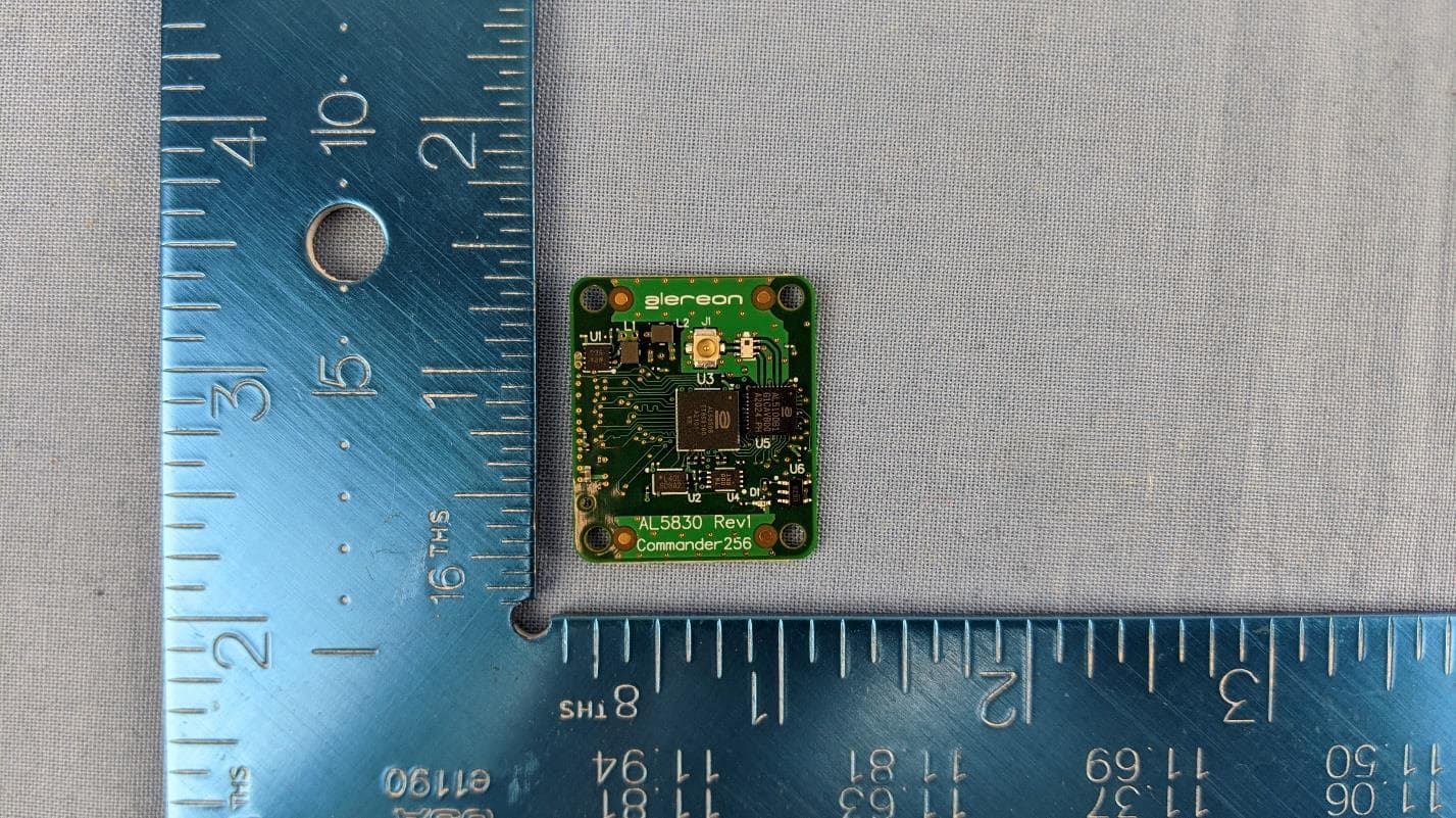
U9YAL5830
Apr 19, 2021UWB Parallel Interface Module (SBU & SAB)
Equipment Class
UWB - Ultra Wideband Transmitter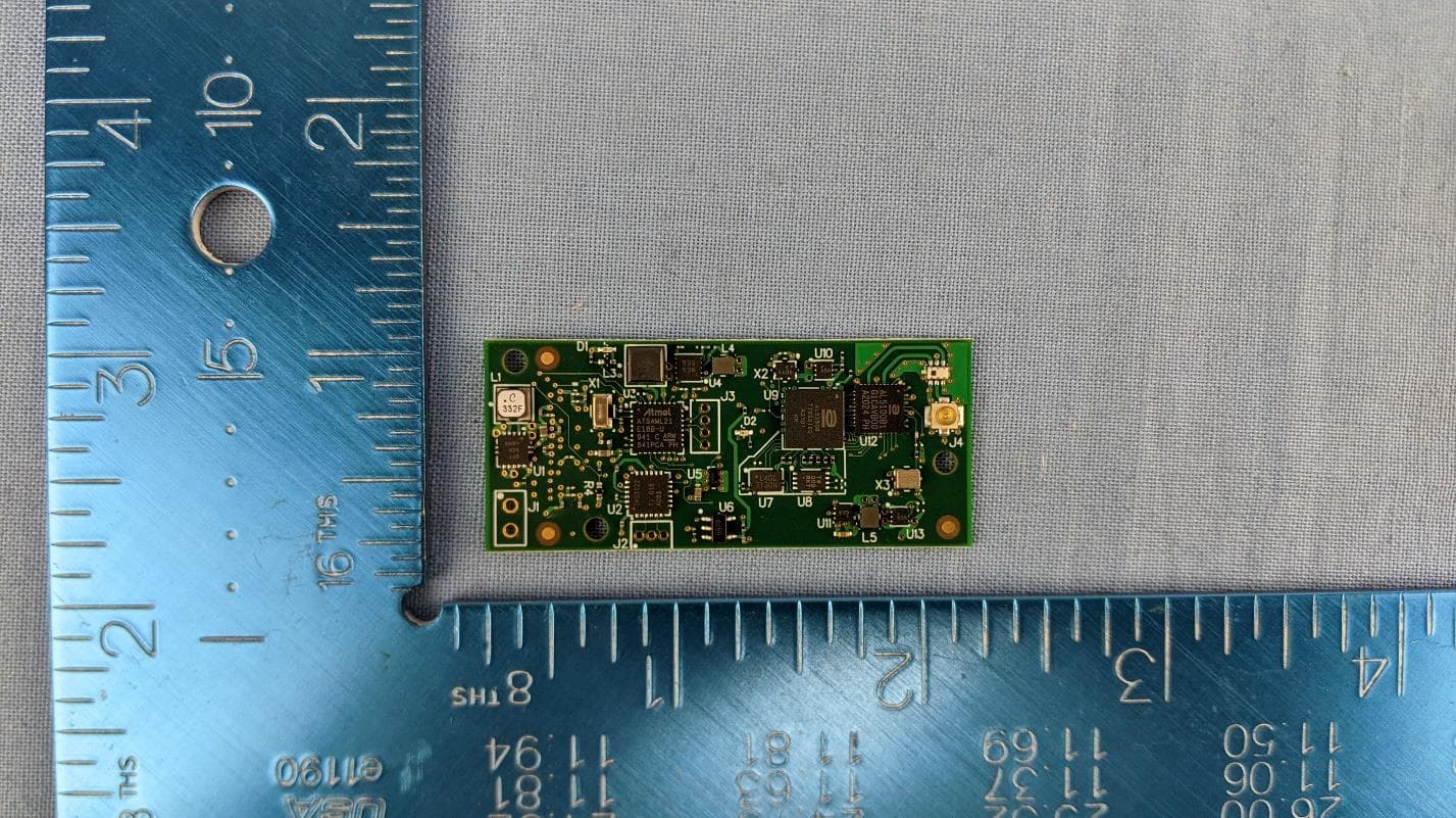
U9YAL5835
Apr 19, 2021UWB Serial Interface Module (SBU & SAB)
Equipment Class
UWB - Ultra Wideband Transmitter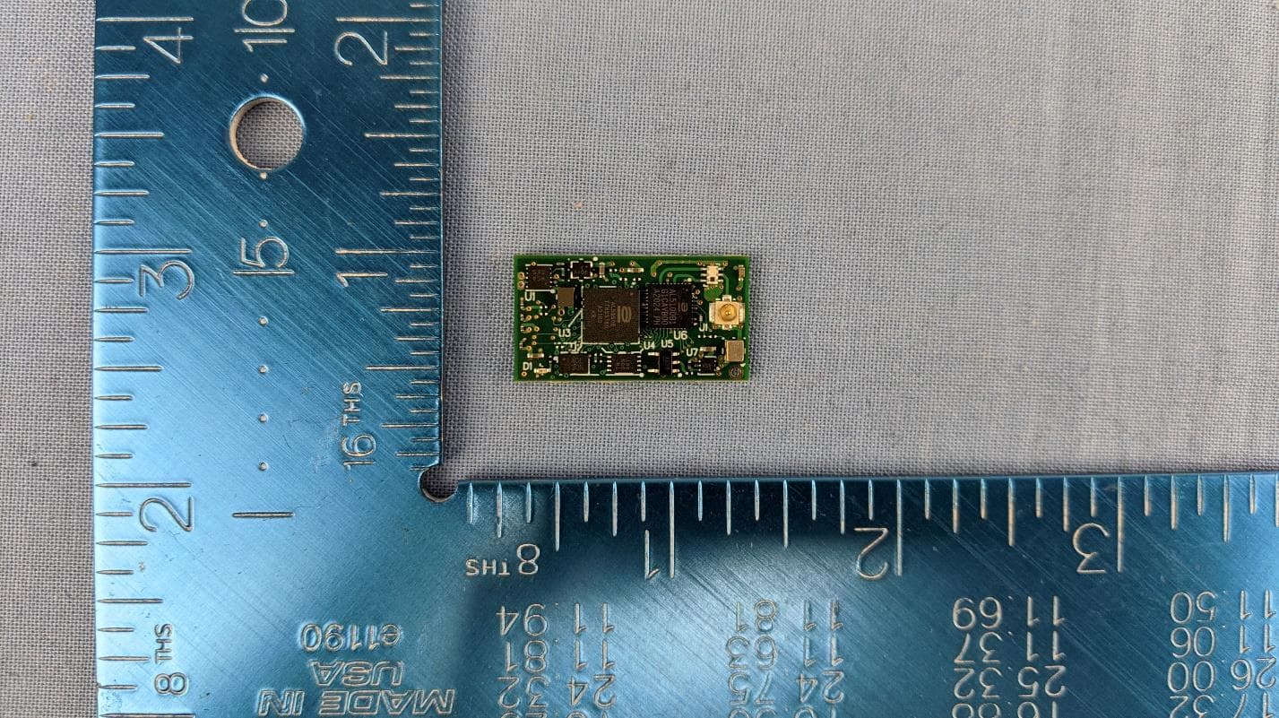
U9YAL5808
Apr 13, 2021UWB Octal SPI Module (SBU & SAB)
Equipment Class
UWB - Ultra Wideband Transmitter
U9YAL5833
Apr 13, 2021UWB Parallel Interface Module (SBU & SAB)
Equipment Class
UWB - Ultra Wideband Transmitter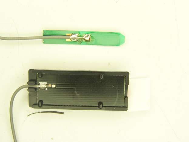
U9YHS6621
Aug 13, 2012Wireless USB Module
Equipment Class
UWB - Ultra Wideband Transmitter