UA2OT4XXXBHONOmniAssure Touch
Novar GmbH
Click to zoom
Application Details
- Equipment Class
- JAB - Part 15 Class B Digital Device
- Date of Grant
- Apr 07, 2020
- Application Purpose
- Original Equipment
- Date of Application
- Mar 25, 2020
- Equipment Note
- OmniAssure Touch
- Company
- Novar GmbH
- Country
- Germany
Documents & Files
Document Text
Text extracted from the exhibit documents filed with the FCC. Open a document above to read the original.
Users Manual
Installation Instructions /OmniAssure Touch Square OmniAssure Touch Square P30742-10-0G0-01 2019-05-07 ENInstallation Instructions......................................2 This documentation can be downloaded from our websites in English, German, French, Spanish, Italian, Portuguese, Czech, Polish, Russian, Turkish and Mandarin. GLOBAL: DACH: www.security.honeywell.com www.security.honeywell.de Model nameSmartproXMobileColorItem. no. XXXBlackOT4800BHONG OmniAssure Touch Square XXBlackOT4700BHONG XXXBlackOT4816BHONG OmniAssure Touch Square 16 key XXBlackOT4716BHONG XXXWhiteOT4800WHONG OmniAssure Touch Square XXWhiteOT4700WHONG XXXWhiteOT4816WHONG OmniAssure Touch Square 16 key XXWhiteOT4716WHONG I II III IV ⑨ ⑩⑪ V 2Installation Instructions / OmniAssure Touch Square Subject to change without notice. 1Scope of delivery 1Installation instructions 1Reader front 1Mounting backplate 5Wall anchors (5 x 25 mm or #8 x 1”) 5Screws (panhead, 3 x 30 mm or #4 x 1¼”) 3Enclosure screws (metric, M2 x 5 mm panhead) 4Enclosure screw caps 2General The OmniAssure Touch Square Reader was tested at the panels: – NetAXS 123 V6 (Wiegand) – ProWatch 6k (Wiegand) – Pro32 (Wiegand) – Mercury EP1502 (OSDP) Mobile credentials: – proX (EM4102) – MIFARE classic – MIFARE DESFire EV1/EV2 – OmniAssure OES – QKey – HID – ISO-SNR Quadrakey – Bluetooth Low Energy Physical interfaces: – Wiegand – RS-485 (OSDP 2.1.7.) The Reader Utility Application is used to configure: – credential bit formats and length 3Installation All dimensions in drawings are in mm. NOTE All wiring shall be in accordance with applicable codes and regulations. Observe applicable building codes and safety regulations in determining the reader position. UL 294: Installation must be done in accordance with National Electrical Code, ANSI/NFPA 70. General terms – The reader base can be used as a drilling template where necessary. – When positioning the reader base, ensure that the backtamper can be securely screwed in; otherwise the tamper detection is reduced to opening monitoring. – We recommend that the connection cable of the reader is guided through the reader base from the side with the lettering reading "Hon- eywell" before fixing the reader base. – Secure the reader base without exerting excessive force. – Use the mounting material included in the accessories. If you need more materials, ensure that these have the same diameter. –The power supply of the reader must be switched off while the reader is connected. Risk of damage! 3.1Important notes on mounting – Pay attention to the minimum distances (see "V", page 1). Mounting readers in close proximity of each other will reduce perfor- mance, the minimum recommended mounting distance side-by-side or back-to-back is 125 mm (5”). – Mounting the reader on a metal surface may reduce performance, a plastic separator of at least 6 mm (¼”) is recommended. 3.1.1Mounting height In order to operate the keypad and read the indications optimally, install the reader at a height of 130 to 140 cm (51 to 55”) above the floor. 3.1.2Necessary cable reserve In order for the reader to be able to dismounted when necessary, there must be a sufficient cable reserve in the direct vicinity of the reader. Depending on the type of mounting, the cable reserve can be placed in the flush mounted socket, or in a nearby junction box. 3.1.3Outdoor use – If the reader is to be used outdoors, the cable entry must be sealed on both sides of the wall, to prevent condensation. – The connector for the connection cable of the reader should be located indoors. 3.2Mounting for flush mounted wiring see "I", page 1 Screw the reader base onto a DIN-style f.m. socket [1] (preferred mount- ing) or directly onto the wall. For sockets from Switzerland, the reader is fixed at the corners. Screw the backtamper [2] onto the wall, so that if the reader is torn off the wall, the actuator pin [3] remains secured to the wall, thus releasing the cover contact and signalling a tamper situation. 3.3Mounting for surface mounted wiring with wall plate see "II", page 1 Place the wall plate for surface mounting [4] (Item no. LU45BB) between the reader base [5] and the wall and screw both firmly onto the wall. Then screw on the tear-off protection (see chapter "Mounting for flush mounted wiring"). The wall plate can be rotated in 90° steps so that the surface mounted cable entry [6] can be from at the bottom, at the top, on the left or right. 3.4Mounting with Visual Cover see "III", page 1 The visual cover (item no. OT4XBHONG/OT4WHONG) is suitable for flush wiring and surface wiring. The mounting is identical to the mounting with the wall plate. Note that the visual cover cannot be rotated. For this reason, a surface mounted cable entry [7] is therefore only possible from below or above. Break [8] if necessary. For a lateral cable entry, it is therefore necessary to provide the wall plate under the sight protection. 3.5Fasten the reader see "IV", page 1 [9] Hang the reader from above in the reader base. [10] Snap shut below. [11] Close with the two attached screws. After completing the mounting and functional testing seal the housing. To do this, press the enclosed seals into screw holes. Installation Instructions / OmniAssure Touch Square3 3.6Test the reader / Commissioning Apply power (the green LED indicates power) and present a valid creden- tial. The light ring should flash and the sounder should produce a short tone indicating a successful read. If the Host system is connected the light ring and sounder should follow the functionality of the Host system. 3.7Cable specification – The reader is supplied with 2 m (6 ft.) of shielded, 8-conductor 0,14 mm² (AWG 26) cable which may be extended with the length and size of cable listed below. min. conductor size for panel power suppy max. cable length 9,5 V 1) 12 V18 V Interface metersfeetmm²AWGmm²AWGmm²AWG 612000,55200,33220,2224 913000,82180,5200,3322 Wiegand / RS-485 (cable power) 1525001,35160,81180,5420 RS-485 (l…
Text truncated - open the document above for the full version.
External Photos
Page 1 of 2 External Photo Module Product name : Omniassure Touch FCC ID : UA2OT4XXXBHON IC ID : Test report No. 181201116 Test report No. 181201116 Page 1 of 2 Table of Contents 1 External Photos ........................................................................................................................................ 2 1.1 Front View ............................................................................................................................................. 2 1.2 Back view (normally mounted against wall) ......................................................................................... 2 Test report No. 181201116 Page 2 of 2 1 External Photos 1.1 Front View 1.2 Back view (normally mounted against wall)
ID Label/Location Info
Honeywell Security Deutschland FS-RD-00014-E / OCT-16-2013 release B page 1 of 6 (x) Manufacturing Requirements () pre Manufacturing Requirements Sub-assembly-description: OmniAssure Touch Square OT4716BHONG, OT4700BHONG, OT4800BHONG, OT4816BHONG Sub-assembly-number: SA_GRSMCSG16B, SA_GRSMCSG0B, SA_GRSPMCSG0B, SA_GRSPMCSG16B PCB-numbers: Created: T. Finke R&D-HW *) Checked: OP *) Released: Project leader *) Comments: The change are marked. 800-24814 *) Approvals will be done with Agile workflow. No hand signature required on this document. Honeywell Security Deutschland FS-RD-00014-E / OCT-16-2013 release B page 2 of 6 In general the standard manufacturing methods and processes which comply with “Quality Manual” have to be applied. The following document only covers special operations and workflows which were not defined in process descriptions and operating instructions or diverge from it. Production workflow Visual incoming inspection for all OmniAssure Touch parts. The following parts should be delivered by INID: - 2D label - type label - wall plate - reader + module Incoming inspection of reader, BLE module and 2D label position: BLE module with RF cover cable tie 2D label wall plate 2D label Type label (example) Honeywell Security Deutschland FS-RD-00014-E / OCT-16-2013 release B page 3 of 6 Please assemble the two rubber sleeves: The switch and buzzer gaps/openings must be covered with PC-FLEX-MASK (or similar technics) as shown in the picture: Wait until PC-FLEX-MASK is cured (12hours). 2D label position Honeywell Security Deutschland FS-RD-00014-E / OCT-16-2013 release B page 4 of 6 Check the correct assembly of the BLE module: Fill up the enclosure with potting until the height of the rubber sleeves. Follow the following steps: Fill the cavity between main PCB and keyboard through the fill hole next to the buzzer, use a tight-fitting nozzle and a very low flow rate (suggested: 0.25 ml/s). Approx. 11 ml is required. Watch out for potting coming up through the cable opening prematurely, pause a second or two if necessary. Leave potting to settle into all voids, verify that the potting fills the holes above the BLE module and in the top left corner from below; this can take up to 30 seconds depending on initial flow rate. Fill the rest of the reader to the required fill height from the middle of the reader using a suitable flow rate, avoid bubbles forming (e.g. on corners of components). Verify that the space between the main PCB and the BLE module is filled by checking the opening in the bottom right corner between the BLE module and the housing. Cover the BLE module with a thin layer of potting, several drops should suffice. Afterwards the potting must cure. During that time, do not move the device. Keep the device in a stable horizontal position. Cure time of the potting is at least 24 hours (hardening at higher temperature is forbidden). Remove PC-FLEX-MASK from switch and buzzer. Test in according with the test requirements. Remove the clamp terminal block (if available). The product label and type label should be stick on the potting in compliance with the picture. Check the BLE module is mounted here correctly on that position with that pattern Make sure the BLE module plugs in correctly between multi-pin connector<->socket terminal Honeywell Security Deutschland FS-RD-00014-E / OCT-16-2013 release B page 5 of 6 Put in 4 screw covers (INID) in the accessory bag. Put in the manual, the wall plate and accessory bag under the inlay in the packaging box. Afterwards the inlay and reader on top as shown in the picture (example for square). Remove the protection (manufacture) foil on top. Close the box with the packaging label in place (uncertainty in ±1cm). See document 800-16060 “Labeling Gift-Boxes Albstadt” for label placement on the outer packaging. Product label Type label (example) Honeywell Security Deutschland FS-RD-00014-E / OCT-16-2013 release B page 6 of 6 Pull over the slip case. L/2±1cm L = box length
Internal Photos
Page 1 of 3 Internal Photo Module Product name : Omniassure touch FCC ID : UA2OT4XXXBHON IC ID : Test report No. 181201116 Test report No. 181201116 Page 1 of 3 Table of Contents 1 Internal Photos ........................................................................................................................................ 2 1.1 Front PCB view (conducted sample) ..................................................................................................... 2 1.2 Back PCB view ....................................................................................................................................... 2 1.3 RF section view (radiated sample) ..........................................................Error! Bookmark not defined. Test report No. 181201116 Page 2 of 3 1 Internal Photos 1.1 Front PCB view (main) 1.2 Back PCB view (main) Test report No. 181201116 Page 3 of 3 1.3 Front BLE module view 1.4 Back BLE module view
Test Report
FCC and IC Test report for parts 15.207, 15.209, 15.225, 15.247 RSS-210, RSS-247, RSS-Gen Product name : OmniAssure Touch Applicant : Novar GmbH – Honeywell Security group FCC ID : UA2OT4XXXBHON IC ID : 6587A-OT4XXXBH Test report No. : 181201116 004 Ver 1.00 Report number: 181201116 004 Ver 1.00 Page 1 of 37 Laboratory information Accreditation Telefication complies with the accreditation criteria for test laboratories as laid down in ISO/IEC 17025:2005. The accreditation covers the quality system of the laboratory as well as the specific activities as described in the authorized annex bearing the accreditation number L021 and is granted on 30 November 1990 by the Dutch Council For Accreditation (RvA: Raad voor Accreditatie). Telefication is designated by the FCC as an Accredited Test Firm for compliance testing of equipment subject to Certification under Parts 15 & 18. The Designation number is: NL0001. Telefication is a Wireless Device Testing laboratory recognized by Innovation, Science and Economic Development Canada to test to Canadian radio equipment requirements. The Industry Canada registration number for the 3 meter test chamber of Telefication is: 4173A-1. Telefication is a registered Conformity Assessment body (CAB) under the Japan-EC MRA (Agreement on Mutual Recognition between Japan and the European Community). The registration number is: 201. Documentation The test report must always be reproduced in full; reproduction of an excerpt only is subject to written approval of the testing laboratory. The documentation of the testing performed on the tested devices is archived for 10 years at Telefication Netherlands. Testing Location Test Site Telefication BV Test Site location Edisonstraat 12a 6902 PK Zevenaar The Netherlands Tel. +31316583180 Fax. +31316583189 Test Site FCC NL0001 Report number: 181201116 004 Ver 1.00 Page 2 of 37 Revision History Version Date Remarks By v0.50 31-01-2019 First draft PvW v1.00 05-06-2019 Final version PvW Report number: 181201116 004 Ver 1.00 Page 3 of 37 Table of Contents Revision History .............................................................................................................................................. 2 Summary of Test results .................................................................................................................................. 6 1 General Description ................................................................................................................................. 7 1.1 Applicant ................................................................................................................................................ 7 1.2 Manufacturer ........................................................................................................................................ 7 1.3 Tested Equipment Under Test (EUT) ..................................................................................................... 7 1.4 Product specifications of Equipment under test ................................................................................... 8 1.5 Environmental conditions...................................................................................................................... 8 1.6 Measurement standards ....................................................................................................................... 8 1.7 Applicable standards ............................................................................................................................. 8 1.8 Observation and remarks ...................................................................................................................... 9 1.9 Conclusions .......................................................................................................................................... 10 2 Test configuration of the Equipment Under Test ................................................................................... 11 2.1 Test mode ............................................................................................................................................ 11 2.2 Test setups ........................................................................................................................................... 11 2.3 Equipment used in the test configuration ........................................................................................... 13 2.4 Sample calculations ............................................................................................................................. 13 3 Test results ............................................................................................................................................ 14 3.1 Field strength of emissions .................................................................................................................. 14 3.1.1 Limit ................................................................................................................................................. 14 3.1.2 Measurement instruments ............................................................................................................. 14 3.1.3 Test setup ........................................................................................................................................ 14 3.1.4 Test procedure ................................................................................................................................ 14 3.1.5 Test results of Field strength of emissions ...................................................................................... 14 3.1.6 Plots of Field strength of emissions Measurement ......................................................................... 15 3.2 Radiated spurious emissions ............................................................................................................... 16 3.2.1 Limit .......................…
Text truncated - open the document above for the full version.
Test Setup Photos
Page 1 of 4 Test Setup Photo Module Product name : Omniassure Touch FCC ID : UA2OT4XXXBHON IC ID : 6587A-OT4XXXBH Test report No. 181201116 Test report No. 181201116 Page 1 of 4 Contents 1 Test Setup Photos .................................................................................................................................... 2 1.1 Radiated emissions measurement 9 kHz – 30 MHz (Perpendicular) .................................................... 2 1.2 Radiated emissions measurement 9 kHz – 30 MHz (Orthogonal) ........................................................ 2 1.3 Radiated emissions measurement 30 – 1000 MHz ............................................................................... 3 1.4 Radiated emissions measurement 1 – 18 GHz ...................................................................................... 3 1.5 Radiated emissions measurement 18 - 26 GHz..................................................................................... 4 Test report No. 181201116 Page 2 of 4 1 Test Setup Photos 1.1 Radiated emissions measurement 9 kHz – 30 MHz (Perpendicular) 1.2 Radiated emissions measurement 9 kHz – 30 MHz (Orthogonal) Test report No. 181201116 Page 3 of 4 1.3 Radiated emissions measurement 30 – 1000 MHz 1.4 Radiated emissions measurement 1 – 18 GHz Test report No. 181201116 Page 4 of 4 1.5 Radiated emissions measurement 18 - 26 GHz
Contact Information
Applicant
Klaus-Dieter Wank
Technical Contact
Non-Technical Contact
Novar GmbHKlaus Wank
[email protected]004974318011210
Test Firm
Kiwa Nederland B.V.Willem Jong
[email protected]+31 889983621
Technical Specifications
| # | Rule Parts | Frequency Range | Power Output |
|---|---|---|---|
| 1 | 15B | - | - |
Other Applications from Novar GmbH

UA2OT3XXXBHON
Apr 07, 2020wireless card reader
Equipment Class
DCD - Part 15 Low Power Transmitter Below 1705 kHz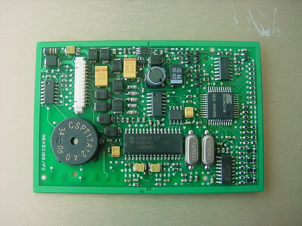
UA2X0402100
Sep 26, 2006RFID Reader Module
Equipment Class
DXX - Part 15 Low Power Communication Device Transmitter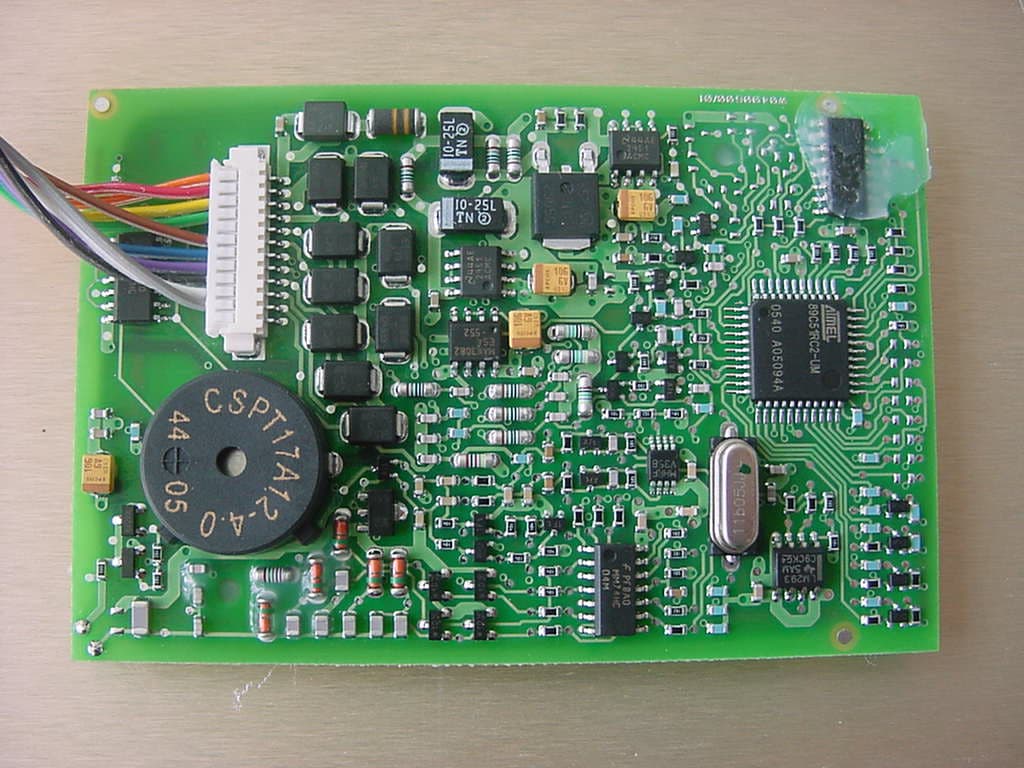
UA2X0400600
Sep 26, 2006RFID Reader Module
Equipment Class
DCD - Part 15 Low Power Transmitter Below 1705 kHz