UA3ATR20101-4Fixed Reader
CommerceGuard AB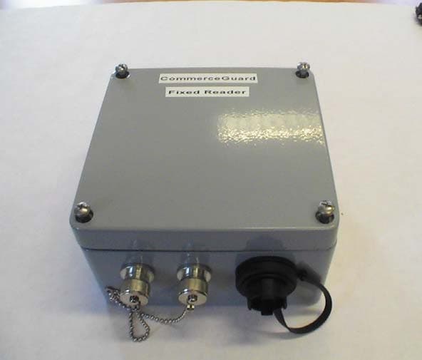
Click to zoom
Application Details
- Equipment Class
- DTS - Digital Transmission System
- Date of Grant
- Sep 28, 2006
- Application Purpose
- Original Equipment
- Date of Application
- Sep 28, 2006
- Equipment Note
- Fixed Reader
- Frequency Range
- 2440.00000000 - 2440.00000000
- Company
- CommerceGuard AB
- Country
- Sweden
Documents & Files
Document Text
Text extracted from the exhibit documents filed with the FCC. Open a document above to read the original.
External Photos
Fixed Reader GE CommerceGuard AB 1 Case view 1.1 Top 1.2 Side
ID Label/Location Info
Fixed Reader GE CommerceGuard AB Trade Name: CommerceGuard Fixed Reader Model No: CG-FR03 Fixed Reader GE CommerceGuard AB 1 Label 1 2 Label 2 Fixed Reader GE CommerceGuard AB 3 Label Positions Label 2 Label 1
Operational Description
Fixed Reader Brief Operational Description GE CommerceGuard AB Prepared (Also subject responsible if other) Date Security Class Ola Myrin 2006-08-21 Confidential Approved Document No. Rev. A 1 (5) Fixed Reader (CG-FR03) Brief Operational Description Fixed Reader Brief Operational Description GE CommerceGuard AB Prepared (Also subject responsible if other) Date Security Class Ola Myrin 2006-08-21 Confidential Approved Document No. Rev. A 2 (5) 1 Background The CommerceGuard Fixed Reader is an Ethernet to RF transceiver. Its external connectors are • Two N style antenna connectors • One Ethernet connector that also contains 12VDC power supply to the unit. The circuit board contains a microprocessor, DC/DC converter, two 2.44GHz radios, ethernet controller, glue logic and memory. The Fixed Reader is used to scan for CSDs. When communications is established with a CSD, the Fixed Reader translates the 2.44GHz into Ethernet protocol that can be utilized by an external host. The Fixed circuit board utilizes a 4-layer configuration that optimizes the RF performance using appropriate ground planes. Fixed Reader Brief Operational Description GE CommerceGuard AB Prepared (Also subject responsible if other) Date Security Class Ola Myrin 2006-08-21 Confidential Approved Document No. Rev. A 3 (5) 2 Block Diagram Outside interface Channel A Power over Ethernet, 12VDC Balun Murata LDB312G402C - 301 4 pole cavity bandpass filter -3dB: 30MHz -45dB: 50MHz RFWaves RFW24 RFWaves RFW- D100 -Data I/O - Enable - RX orTX mode LO 488MHz Renesas M16C Transformer and filter Crystal 10MHz Crystal 25MHz Davicom DM9000 Channel B Switched power supply Balun Murata LDB312G402C - 301 RFWaves RFW24 RFWaves RFW- D100 -Data I/O - Enable - RX orTX mode LO 488MHz 4 pole cavity bandpass filter -3dB: 30MHz -45dB: 50MHz 20MHz 20MHz Chassie ground to all parts ethernet ethernet Fixed Reader Brief Operational Description GE CommerceGuard AB Prepared (Also subject responsible if other) Date Security Class Ola Myrin 2006-08-21 Confidential Approved Document No. Rev. A 4 (5) 3 Operational Description Microcontroller The microcontroller is a 16-bit MCU. It controls all functions on the board. It has a 10.000 MHz crystal and an internal PLL that multiply the external clock by 2 so the core is running at 20MHz. A 32 Mbit memory is accessed through the 16bit data bus. Extra glue logic is used to create extra chip select signals. Ethernet controller, Davicom The ethernet controller takes care of the ethernet communication. It has a 25.000 MHz crytal and provides a divided down signal of 20.000 MHz on an output. The radio base band chips use this 20MHz signal. Start-up parameters are stored in an EEPROM connected to the ethernet controller. Tree LEDs are available for link status information. Ethernet transformer The ethernet transformer isolates the Fixed reader and filters the signal. A diode network adds ESD protection. DC/DC converter A diode bridge protects the Fixed reader from wrong polarity. The DC/DC converter is a buck-converter with a good filter capacitor on the input. The down converted voltage is distributed to tree LDOs that regulates the voltage to 3.3V and increase the isolation between the different loads. A voltage monitor creates a good power signal and resets the fixed reader if the digital system voltage drops below 3.0V. Radio and baseband (RFWaves RFW122M and D100) The MCU communicates with the D100, which control the RFW122M. The D100 is a baseband circuit that takes care of the low-level part of the radio protocol, it adds and controls checksum, adds pre-amble etc). It puts the RFW122M in RX or TX mode. It receives (RX) serial data or transmits (TX) serial data. A 20 MHz signal from the ethernet chip is used to run the D100. Fixed Reader Brief Operational Description GE CommerceGuard AB Prepared (Also subject responsible if other) Date Security Class Ola Myrin 2006-08-21 Confidential Approved Document No. Rev. A 5 (5) The RFW122M is a pre-fabricated PCBA with components that is mounted onto the Fixed reader PCB. This module contains IF filter with matching, RFIC and LO resonator. The RFIC contains a LNA, a PA. They all have a fixed performance that can’t be changed. The LO is operating at a fixed frequency of 488 MHz. The LO frequency is multiplied by four and mixed with the IF to create the carrier at 2440 MHz. The occupied bandwidth of this signal is approx 20MHz for 99% of the power within the measured bandwidth. The RFIC also outputs an analogue signal strength indicator that is sampled by the MCU. The balanced I/O of the RFW122M is converted to single ended by the balun. A 5bit, 1dB resolution step attenuator is used to set the output power at production. An external PA is used to increase the output power at the antenna. An external LNA is used to increase the receiver sensitivity. The VSWR detector is used to detect a missing/faulty antenna. The 4-pole cavity filter has an extremely sharp roll off and attenuates all spurious frequencies outside the 2400 to 2483.5 MHz band. Abbreviations IF Intermediate frequency LDO Low Drop Out (voltage regulators) LEDs Light Emitting Diods LNA Low Noise Amplifier LO Local Oscillator PA Power Amplifier PCB Printed Circuit Board PCBA Printed Circuit Board Assembly RFIC Radio Frequency Integrated Circuit VSWR Voltage Standing Wave Ratio
Test Setup Photos
1(3) TEST SET-UP PHOTOS CG-FR03 Radiated spurious emission 30-1000 MHz 2(3) Radiated spurious emission 1-26 GHz 3(3) Conducted disturbance voltage at AC terminal
Contact Information
Applicant
James Petrizzi(VP Engineering)
Technical Contact
GE CommerceGuard ABOla Myrin
[email protected]+46-709-85 22 21
Gustavslundsvagen 151A · Bromma · Sweden
Non-Technical Contact
GE CommerceGuard ABOla Myrin
+46-709-85 22 21
Test Firm
Intertek SEMKO ABNiklas Bostrom
Technical Specifications
| # | Rule Parts | Frequency Range | Power Output |
|---|---|---|---|
| 1 | 15C | 2.44 GHz - 2.44 GHz | 1.70 mW |
Other Applications from CommerceGuard AB
UA3-ATR20107-1
Dec 12, 2006CG-CFR03
Equipment Class
DTS - Digital Transmission System
UA3ATT10102-5
Sep 21, 2006Container Security Device
Equipment Class
DTS - Digital Transmission System