UAB937R01Wireless Towing lights
Many Wain Enterprise Co., Ltd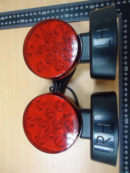
Click to zoom
Application Details
- Equipment Class
- DXX - Part 15 Low Power Communication Device Transmitter
- Date of Grant
- Aug 17, 2014
- Application Purpose
- Original Equipment
- Date of Application
- Aug 17, 2014
- Equipment Note
- Wireless Towing lights
- Frequency Range
- 904.60000000 - 925.40000000
- Country
- Taiwan
Documents & Files
Document Text
Text extracted from the exhibit documents filed with the FCC. Open a document above to read the original.
Users Manual
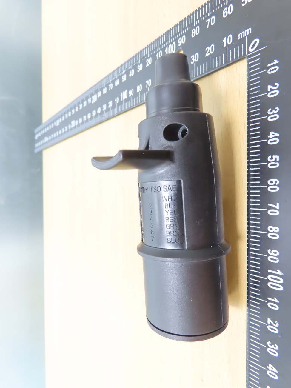
WIRELESS MAGNETIC TOW LIGHT Model: PY-937 This product is intended for temporary use to provide tail light function as well as stop and turn light when towing a vehicle narrower than 80 inches wide. Only use with standard 12 Volt vehicle systems. Limitation: Do not operate towing lights farther than 19.8 meters (65 feet) from the transmitter. Transmitter and Vehicle Plug Wiring Scheme: White – Ground Brown – Tail / Running Lights Yellow – Left Brake / Left Turn Signal Green – Right Brake / Right Turn Signal Operating: 1) Install AA size batteries into both “LH” and “RH” light base per indicated polarity. 2) Connect the transmitter to your “four-flat” trailer plug on the vehicle. 3) Clean the mounting surface and transmitter’s magnetic base. Then attach the transmitter to a steel surface in the rear of towing vehicle. 4) Lights should be placed at the same height. Don’t mount both lights lower than 38.1cm (1.25 feet) or higher than 1.8M (6 feet) from the ground. Attach the “LH” and “RH” lights on a flat surface as practical and at an equal distance from the sides of the vehicle being towed. The entire magnet must touch the steel surface for optimal holding performance. Place lights to allow following vehicles optimal visibility at all times. If the lights aren’t aligned properly, detaching them by tipping the light to disengage the magnetic base before placing them again. 5) Don’t cover or obstruct the lights during operation. Use a tie wrap to collect any loose cable between the lights. 6) Turn “ON” the switch located on the bottom of the “LH” base. 7) Verify the function of left/right turn, tail lights and stop lights. Do not drive your vehicle unless all lights function! 8) Switch off the lights after each use. If the lights are stored for longer than one month, please remove the batteries and store batteries at room temperature to avoid battery leakage. Do not allow the magnetic bases to come in contact with each other. Important: 1.Every 2 hours confirm that your brake, turn signal and running lights are operating correctly. Do not operate your tow lights if the vehicle has faulty wiring or if some or all of the lights do not light. 2.For temperature below 20°F batteries may need to be changed more often. The LED near the top center of the “LH” light will blink amber if battery power is low. Immediate install all new batteries in both tow lights to ensure safe operation and to meet SAE/FMVSS 108 safety standards. 3.Do not submerge the lights or transmitter in water. Damage may occur. 4.Always have a spare set of eight AA batteries on hand, especially if travelling for an extended period of time. Troubleshooting: 1.If your towing vehicle has rear turn signals separate from the stop light, a LED light Bulb load-Resistor Kit available from an automotive accessory supplier may be necessary for turn signals to flash properly. 2.If one or both tow lights do not function, check and/or replace all batteries. Placing four batteries into each base with polarity as indicated. 3.If left / right turn functions are reversed, then reverse the yellow and green wires to the transmitter. 4.If only some lamp functions work while others do not, look over the wiring diagram and check that the four-flat trailer connector i s wired correctly. 5.Check the connection between the “four-flat” plugs for corrosion. Remove corrosion with baking soda and a small disposable brush while wearing gloves. Rev.0 (Jun. 2014) Fed eral Communication Commission Interference Statement This equipment has been tested and found to comply with the limits for a Class B digital device, pursuant to Part 15 of the FCC Rules. These limits are designed to provide reasonable protection against harmful interference in a residential installation. This equipment generates, uses and can radiate radio frequency energy and, if not installed and used in accordance with the instructions, may cause harmful interference to radio communications. However, there is no guarantee that interference will not occur in a particular installation. If this equipment does cause harmful interference to radio or television reception, which can be determined by turning the equipment off and on, the user is encouraged to try to correct the interference by one of the following measures: . Reorient or relocate the receiving antenna. . Increase the separation between the equipment and receiver. . Connect the equipment into an outlet on a circuit different from that to which the receiver is connected. . Consult the dealer or an experienced radio/TV technician for help. FCC Caution: To assure continued compliance, any changes or modifications not expressly approved by the party responsible for compliance could void the user's authority to operate this equipment. (Example - use only shielded interface cables when connecting to computer or peripheral devices). This device complies with Part 15 of the FCC Rules. Operation is su bject to the following two conditions: (1) This device may not cause harmful interference, and (2) This device must accept any interference received, including interference that may cause undesired operation.
External Photos
Registration number: W6M21403-14019-C-1 FCC ID: UAB937R01 Worldwide Testing Services(Taiwan) Co., Ltd. Appendix Page 22 of 38 External Photos Registration number: W6M21403-14019-C-1 FCC ID: UAB937R01 Worldwide Testing Services(Taiwan) Co., Ltd. Appendix Page 23 of 38 Registration number: W6M21403-14019-C-1 FCC ID: UAB937R01 Worldwide Testing Services(Taiwan) Co., Ltd. Appendix Page 24 of 38 Registration number: W6M21403-14019-C-1 FCC ID: UAB937R01 Worldwide Testing Services(Taiwan) Co., Ltd. Appendix Page 25 of 38 Registration number: W6M21403-14019-C-1 FCC ID: UAB937R01 Worldwide Testing Services(Taiwan) Co., Ltd. Appendix Page 26 of 38 s Registration number: W6M21403-14019-C-1 FCC ID: UAB937R01 Worldwide Testing Services(Taiwan) Co., Ltd. Appendix Page 27 of 38 Registration number: W6M21403-14019-C-1 FCC ID: UAB937R01 Worldwide Testing Services(Taiwan) Co., Ltd. Appendix Page 28 of 38
Internal Photos
Registration number: W6M21403-14019-C-1 FCC ID: UAB937R01 Worldwide Testing Services(Taiwan) Co., Ltd. Appendix Page 29 of 38 Internal Photos Registration number: W6M21403-14019-C-1 FCC ID: UAB937R01 Worldwide Testing Services(Taiwan) Co., Ltd. Appendix Page 30 of 38 Registration number: W6M21403-14019-C-1 FCC ID: UAB937R01 Worldwide Testing Services(Taiwan) Co., Ltd. Appendix Page 31 of 38 Registration number: W6M21403-14019-C-1 FCC ID: UAB937R01 Worldwide Testing Services(Taiwan) Co., Ltd. Appendix Page 32 of 38 Registration number: W6M21403-14019-C-1 FCC ID: UAB937R01 Worldwide Testing Services(Taiwan) Co., Ltd. Appendix Page 33 of 38 Registration number: W6M21403-14019-C-1 FCC ID: UAB937R01 Worldwide Testing Services(Taiwan) Co., Ltd. Appendix Page 34 of 38 Registration number: W6M21403-14019-C-1 FCC ID: UAB937R01 Worldwide Testing Services(Taiwan) Co., Ltd. Appendix Page 35 of 38 Registration number: W6M21403-14019-C-1 FCC ID: UAB937R01 Worldwide Testing Services(Taiwan) Co., Ltd. Appendix Page 36 of 38 Registration number: W6M21403-14019-C-1 FCC ID: UAB937R01 Worldwide Testing Services(Taiwan) Co., Ltd. Appendix Page 37 of 38
Test Report
of Applicant: Many Wain Enterprise Co., Ltd Address: 10, LANE 808, CHUNG SHAN ROAD, SHIN HWA TAINAN CITY 712 Taiwan Tested and Prepared by Worldwide Testing Services (Taiwan) Co., Ltd. FCC Registration No.: 930600 Industry Canada filed test laboratory Reg. No. IC 5679A-1 A2LA Accredited No.: 2732.01 Report No.: W6M21403-14019-C-1 6F, NO. 58, LANE 188, RUEY-KUANG RD., NEIHU TAIPEI 114, TAIWAN, R.O.C. TEL: 886-2-66068877 FAX: 886-2-66068879 E-mail: [email protected] FCC PART 15 SUBPART C TEST REPORT for Wireless Towing lights Model No.: PY-937 FCC ID: UAB937R01 Registration number: W6M21403-14019-C-1 FCC ID: UAB937R01 Worldwide Testing Services(Taiwan) Co., Ltd. Page 1 of 28 TABLE OF CONTENTS 1 GENERAL INFORMATION ..........................................................................................................2 1.1 N OTES..........................................................................................................................................2 1.2 TESTING LABORATORY................................................................................................................3 1.2.1 Location ..............................................................................................................................3 1.2.2 Details of accreditation status ............................................................................................3 1.3 DETAILS OF APPROVAL HOLDER...................................................................................................4 1.4 APPLICATION DETAILS.................................................................................................................4 1.5 GENERAL INFORMATION OF TEST ITEM........................................................................................4 1.6 TEST STANDARDS.........................................................................................................................5 2 TECHNICAL TEST .........................................................................................................................5 2.1 SUMMARY OF TEST RESULTS........................................................................................................5 2.2 TEST ENVIRONMENT....................................................................................................................5 2.3 TEST EQUIPMENT LIST.................................................................................................................6 2.4 GENERAL TEST PROCEDURE........................................................................................................8 3 TEST RESULTS (ENCLOSURE) ..................................................................................................9 3.1 PEAK OUTPUT POWER (TRANSMITTER) ......................................................................................10 3.2 EQUIVALENT ISOTROPIC RADIATED POWER................................................................................16 3.3 RF EXPOSURE COMPLIANCE REQUIREMENTS............................................................................16 3.4 OUT OF BAND RADIATED EMISSIONS.........................................................................................16 3.5 SPURIOUS EMISSION (TX) ...........................................................................................................17 3.6 RADIATED EMISSIONS FROM RECEIVER PART............................................................................20 3.7 R ADIATED EMISSION ON THE BAND EDGE..................................................................................23 3.8 POWER LINE CONDUCTED EMISSION.........................................................................................27 APPENDIX..............................................................................................................................................28 Registration number: W6M21403-14019-C-1 FCC ID: UAB937R01 Worldwide Testing Services(Taiwan) Co., Ltd. Page 2 of 28 1 General Information 1.1 Notes The purpose of conformity testing is to increase the probability of adherence to the essential requirements or conformity specifications, as appropriate. The complexity of the technical specifications, however, means that full and thorough testing is impractical for both technical and economic reasons. Furthermore, there is no guarantee that a test sample which has passed all the relevant tests conforms to a specification. Neither is there any guarantee that such a test sample will interwork with other genuinely open systems. The existence of the tests nevertheless provides the confidence that the test sample possesses the qualities as maintained and that is performance generally conforms to representative cases of communications equipment. The test results of this test report relate exclusively to the item tested as specified in 1.5. The test report may only be reproduced or published in full. Reproduction or publication of extracts from the report requires the prior written approval of the Worldwide Testing Services(Taiwan) Co., Ltd. Tester: March 28, 2014 Leon Chueh Date WTS-Lab. Name Signature Technical responsibility for area of testing: March 28, 2014 Kevin Wang Date WTS Name Signature Registration number: W6M21403-14019-C-1 FCC ID: UAB937R01 Worldwide Testing Services(Taiwan) Co., Ltd. Page 3 of 28 1.2 Testing laboratory 1.2.1 Location OATS No.5-1, Lishui, Shuang Sing Village, Wanli Dist., New Taipei City 207, Taiwan (R.O.C.) 3 meter semi-anechoic chamber No.35, Aly. 21, Ln. 228, Ankang Rd., Neihu Dist., Taipei City 114, Taiwan (R.O.C.) TEL:886-2-6613-0228 FAX:886-2-2791-5046 Company Worldwide Testing Services(Taiwan) Co., Ltd. 6F, NO. 58, LANE 188, RUEY-KUANG RD. NEIHU, TAIPEI 114, TAIWAN R.O.C. Tel : 886-2-66068877 Fax : 886-2-66068879 1.2.2 Details of accreditation status Accredited testing laboratory A2LA accredited number: 2730.01 FCC filed test laboratory Reg. No. 930600 Industry Canada filed test laboratory Reg. No. IC 56…
Text truncated - open the document above for the full version.
Test Setup Photos
Registration number: W6M21403-14019-C-1 FCC ID: UAB937R01 Worldwide Testing Services(Taiwan) Co., Ltd. Appendix Page 38 of 38 Set Up Photo of Radiated Emission
Contact Information
Applicant
SHANG TA LIU(R&D Manager)
Technical Contact
Worldwide Testing Services (Taiwan) Co., Ltd.Tse-Ming Chang
[email protected]+886-2-6606-8877
6F., No. 58, Lane 188, Ruey Kuand Rd. · Taipei · Taiwan
Test Firm
Worldwide Testing Services (Taiwan) Co., Ltd.Rex Kao
Technical Specifications
| # | Rule Parts | Frequency Range | Power Output |
|---|---|---|---|
| 1 | 15C | 904.6 MHz - 925.4 MHz | - |
Other Applications from Many Wain Enterprise Co., Ltd
UAB9371
Aug 13, 2026Wireless Towing Light
Equipment Class
DSR - Part 15 Remote Control/Security Device Transceiver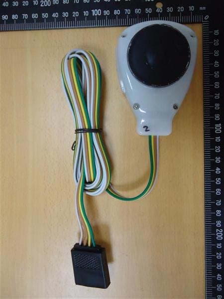
UAB937T01
Aug 19, 2014Wireless Towing lights
Equipment Class
DXX - Part 15 Low Power Communication Device Transmitter