Click to zoom
Application Details
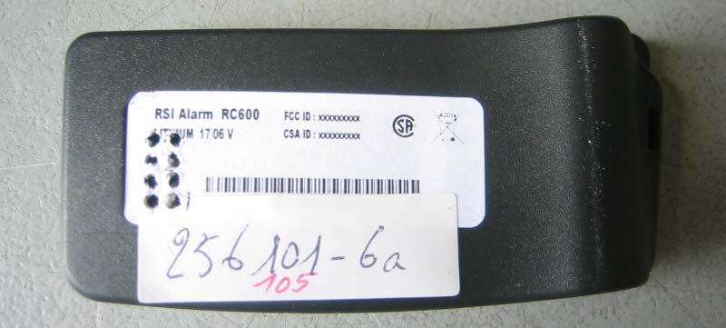
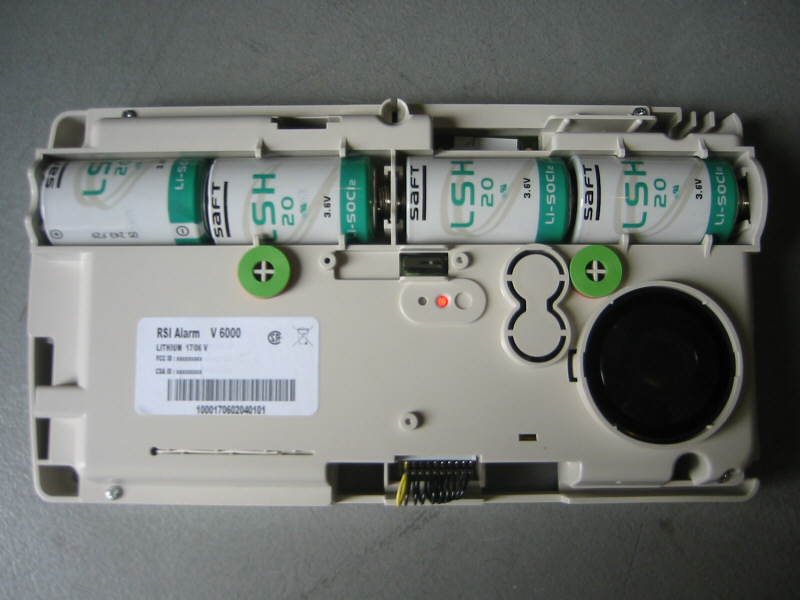
- Equipment Class
- DSS - Part 15 Spread Spectrum Transmitter
- Date of Grant
- Sep 11, 2007
- Application Purpose
- Original Equipment
- Date of Application
- Sep 11, 2007
- Equipment Note
- central of an alarm system
- Frequency Range
- 904.37800000 - 926.22000000
- Company
- RSIAlarm
- Country
- France
Documents & Files
Select a file to view