UDIRPT1900Repeater
Telcosat Inc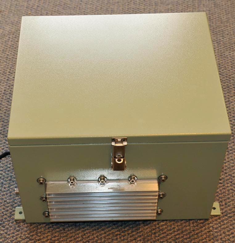
Click to zoom
Application Details
- Equipment Class
- PCB - PCS Licensed Transmitter
- Date of Grant
- Mar 22, 2010
- Application Purpose
- Original Equipment
- Date of Application
- Mar 21, 2010
- Equipment Note
- Repeater
- Frequency Range
- 1930.00000000 - 1990.00000000
- Company
- Telcosat Inc
- Country
- Canada
Documents & Files
Document Text
Text extracted from the exhibit documents filed with the FCC. Open a document above to read the original.
Users Manual
Manual Number: TELCOSAT RPT 1900 Document use is restricted to that described on cover OPERATION & MAINTENANCE MANUAL CELLULAR REPEATER MODEL RPT 1900 Document use is restricted to that described on the cover 2 TELCOSAT INC OPERATIONS & MAINTENANCE MANUAL CELLULAR REPEATER MODEL RPT 1900 TELCOSAT RPT 1900 The information set forth in this document and all rights in and to inventions disclosed herein, and patents which might be granted thereon disclosing, employing or covering the materials, methods, techniques or apparatus described herein are the exclusive property of Telcosat Inc. This document is an operation and maintenance manual. No disclosure or reproduction of the information or drawings shall be made of any other purpose without the prior written consent of Telcosat Inc. Use of the information contained herein to fabricate or assemble any item in whole or in part is expressly prohibited. A Canadian Company 116, 1919 – 27 th Ave NE, Calgary, Alberta, Canada. T2E 7E4 Tel Canada (403) 291-4031 Fax Canada (403) 291-3059 TELCOSAT RPT 1900 Document use is restricted to that described on cover 4 SAFETY SUMMARY High voltage is used in the operation of this equipment. Death on contact may result if personnel fail to observe the following safety precautions: Only qualified trained personnel can install this equipment. Electrical connection and installation must meet your local Electrical Safety Installation codes. Prior to any maintenance or inspection of this device disconnect the power supply. Do not remove covers or access plates on the equipment unless you are a trained technician and authorized to carry adjustment and maintenance for this apparatus. When installing antennas always be aware of high voltage overhead power lines. Contact with power lines will result in severe injury and or death. To prevent electrical shock or damage to the equipment, do not operate the repeater until you thoroughly understand the operation and function of all controls, indicators, and connectors. The RPT1900 Repeater weighs approximately 55 lbs/ 25kilograms. The repeater must be attached to the appropriate supporting device using the welded supporting lugs on the enclosure. The nuts and bolts must be a minimum Grade 5, ¼” (6mm) diameter and corrosion resistant. FIRST AID In case of electrical shock: THIS PERSON COULD STILL BE INCONTACT WITH ELECTRICAL POWER. DO NOT TOUCH THIS PERSON BEFORE YOU INSULATE YOUR SELF FROM THE ELECTRICAL SOURCE. Turn off the electrical power. If you cannot turn off the electrical power, pull, push, or lift the person to safety using a dry wooden pole, a dry rope, or some other insulating material. Do not use any metallic objects to move this person. After the injured person is no longer in contact with the electrical source, obtain/perform immediate medical attention. TELCOSAT RPT 900 Rev. 01 REGULATORY NOTICE Document use is restricted to that described on cover II NOTE RULE: RSS-131 section 5.3 The manufacturers rated output power of this equipment is for single carrier operation. For situations when multiple carrier signals are present, the rating would have to be reduced by 3.5dB, especially where the out-put signal is re- radiated and can cause interference to adjacent band users. This power reduction is to be by means of input power or gain reduction and not by an attenuator at the out-put device FCC/IC RF Exposure Requirements The antenna(s) used for this transmitter must be installed to provide a separation distance of at least 88.09 cm from all persons, and must not be co-located or operating in conjunction with any other antenna or transmitter. This minimum safe distance is based on maximum antenna gain of 18 dBi. Regulatory Notice: Any modifications to this device will void FCC and IC approvals. TELCOSAT RPT 1900 TABLE OF CONTENTS Document use is restricted to that described on cover 5 TABLE OF CONTENTS CHAPTER 1 1.1 GENERAL 1-1 1.2 INTRODUCTION 1-1 1.2.1. HARDWARE DETAILS 1-1 1.3 RPT 1900 SPECIFICATIONS 1-5 1.4 TECHNICAL ASSISTANCE 1-5 CHAPTER 2 OPERATIONAL OVERVIEW 2-1 2.1 GENERAL 2-1 2.2 DETAILED TECHNICAL RF SIGNAL PROCESSES 2-1 2.3 AC POWER DISTRIBUTION 2-2 CHAPTER 3 INSTALLATION 3-1 3.1 WARNING 3-1 3.2 TOOLS REQUIRED 3-1 3.3 ANTENNA REQUIREMENTS 3-1 3.4 ANTENNA ISOLATION & COAX CABLES 3-1 3.5. INSTALLING YOUR REPEATER 3-1 3.6 MANUAL RF GAIN ADJUSTMENTS 3.7 RSSI INDICATOR AND SIGNAL LEVELS 3-2 3.8 ALIGNING YOUR ANTENNA 3-2 3.9 ADJUSTING UPLINK POWER 3-2 CHAPTER 4 WARRANTY REPAIR 4.1 WARRANTY 4.2 LIMITED WARRANTY CHAPTER 5 EQUIPMENT LONG TERM STORAGE APPENDIX B RETURN GOODS PROCEDURE B-1 B2. Returned Goods Procedure B3. Shipping Procedure B4. Returned Shipments B5. Repair / Return Status TELCOSAT RPT 1900 Document use is restricted to that described on cover 1-2 CHAPTER 1 SCOPE 1.1 GENERAL The TELCOSAT RPT 1900 Cellular Repeater (consisting of UPLINK and DOWNLINK bidirectional system) contains operational and maintenance information. This manual consists of four chapters and two appendices as follows: Chapter 1 outlines the manual contents, with description and general application notes Chapter 2 contains an operational overview and tune-up procedures (single and multi carrier). Chapter 3 contains installation procedures, packing and shipping instructions. Chapter 4 contains the repeater warranty information Appendix A contains unit specifications and environmental data. Appendix B contains the return goods procedure. 1.2 INTRODUCTION The TELCOSAT RPT 1900 is an off air bidirectional wireless cellular band amplifier also known as a “Repeater”. The RPT1900 cannot demodulate or modulate the signals that pass through the RPT 1900. The RPT1900 Cellular Repeater will allow cellular coverage to be applied in areas where conventional cellular wireless signals do not reach. These areas may be in tunnels, parking structures, buildings, underground, and signal shadow areas. The Repeater can also be deployed to extend cellular service or direct cellular service to low de…
Text truncated - open the document above for the full version.
External Photos
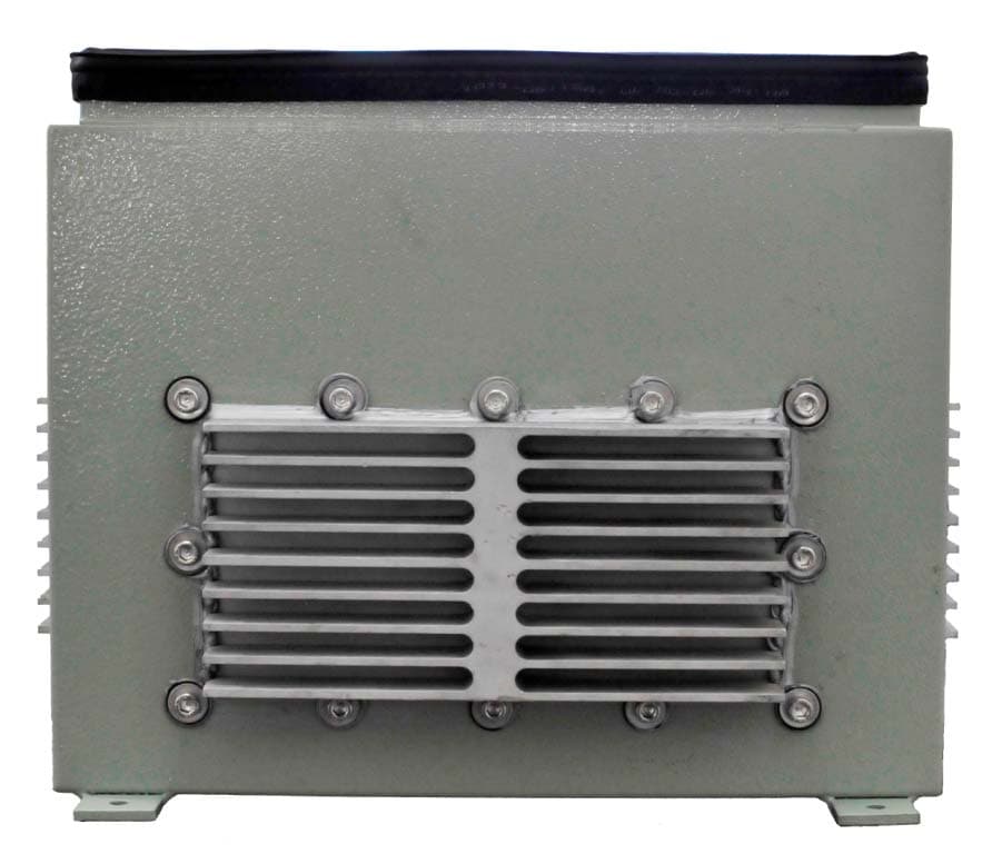
EXTERNAL PHOTOGRAPGHS OF THE RPT1900
ID Label/Location Info
FCC LABEL AND LABEL LOCATION FOR MODEL RPT 1900 BLUE BOX IS THE LOCATION OF THE FCC AND IC LABEL
Internal Photos
INTERNAL PHOTOGRAPHS OF THE RPT1900 CELLULAR REPEATER FRONT AND BACK OF UP/DOWN CONVERTER BOARDS POWER AMPLIFIER BACK AND FRONT OF BOARD
RF Exposure Info
FCC ID: UDIRPT1900 IC: 5842A-RPT1900 Telcosat Inc RF Exposure MPE Exhibit Limits for Occupational/Controlled Exposure Maximum permissible exposure is Freq. (MHz)/1500 = MPE mW/cm 2 1850 MHz/1500 = 1.233 mw/cm 2 The following calculations determine at what distance from the antenna the power density is = 1.233 mw/cm 2 Tx output power = 32.7 dBm Antenna Gain = 18 dBi EIRP of TX and Antenna = 50.7 dBm 50.7 dBm= 120.2 Watts or 120226.4 mW MPE Calculation 2 2 4 )mW/cm( d EIRP PdtyPowerDensi π == Pd EIRP d π4 = 2/233.14 120226.4 cmmw d π = d = 88.09 cm The minimum safe distance for Occupational/Controlled exposure is 88.09cm for the Telcosat RPT1900 antenna when installed. This is the worst case for both the uplink and downlink. The maximum antenna gain stated is for both uplink and downlink. This product is installed by trained professionals in outdoor applications only
Test Report
This report and the information contained herein represent the results of testing articles/products identified and selected by the client. The tests were performed to specifications and/or procedures approved by the client. National Technical Systems (“NTS”) makes no representations expressed or implied that such testing fully demonstrates efficiency, performance, reliability, or any other characteristic of the articles being tested, or similar products. This report should not be relied upon as an endorsement or certification by NTS of the equipment tested, nor does it represent any statement whatsoever as to its merchantability or fitness of the test article or similar products for a particular purpose. This document shall not be reproduced except in full without written approval from National Technical Systems (“NTS”) and the customer Radiated Spurious Emissions Test Report In accordance with FCC Part 24 Industry Canada RSS 133 Telcosat RPT-1900 FCC: UDIRPT1900 IC: 5842A-RPT1900 Project Code CG-1427 (Report CG-1427-EM-2-1) Revision: 1 February 22, 2010 Prepared for: Telcosat Inc. Author: Lixin Wang EMC Technologist Approved by: Nick Kobrosly Director of Canadian Operations CG-1427-EM-2-1 Telcosat Emissions Test Report RPT-1900 FCC: UDIRPT1900 IC: 5842A-RPT1900 The test results contained in this report refer exclusively to the product(s) presented for testing. The test results do not cover models or products not referred herein. This test report should not be published or duplicated in part without permission of the testing body and the customer NTS Product Integrity Laboratory, 5151-47 th Street N.E. Tel: 403-568-6605, Fax: 403-568-6970 Confidential Page 2 of 13 February 22, 2010 Report Summary Test Facility: National Technical Systems, Canada Product Integrity Laboratory 5151-47 th Street, N.E. Calgary Alberta T3J 3R2 Accreditation Numbers: 0214.22 Electrical 0214.23 Mechanical Accredited by A2LA The American Association for Laboratory Accreditation CLIENTS SERVED: All interested parties FIELDS OF TESTING: Electrical/Electronic, Mechanical/Physical ACCREDITATION DATE:: May 14, 2009 VALID TO: February 28, 2010 Applicant: Telcosat Inc. 1#116, 1919-27th Ave N.E. Calgary, AB T2E 7E4 Customer Representative: Aram Sukiasyan 403 291-4031 [email protected] Responsible Manager: Carl Bosnyak 403 291-4031 [email protected] CG-1427-EM-2-1 Telcosat Emissions Test Report RPT-1900 FCC: UDIRPT1900 IC: 5842A-RPT1900 The test results contained in this report refer exclusively to the product(s) presented for testing. The test results do not cover models or products not referred herein. This test report should not be published or duplicated in part without permission of the testing body and the customer NTS Product Integrity Laboratory, 5151-47 th Street N.E. Tel: 403-568-6605, Fax: 403-568-6970 Confidential Page 3 of 13 February 22, 2010 Test Summary Deviations* from: Appendix Test/Requirement Description Base Standard Test Basis NTS Procedure Pass / Fail Applicable FCC Rule Parts Applicable Industry Canada Rule Parts A Field Strength of Spurious Emissions No No No PASS FCC 2.1053, 24.238 RSS-Gen 6.5 Test Result: The product sample presented for testing complied with test requirements as shown in this test summary. Signatures Prepared By: _______________________ Lixin Wang EMC Technologist Reviewed By: ______________________ Glen Moore Wireless/EMC Manager Checked By: ______________________ Alex Mathews Quality Manager CG-1427-EM-2-1 Telcosat Emissions Test Report RPT-1900 FCC: UDIRPT1900 IC: 5842A-RPT1900 The test results contained in this report refer exclusively to the product(s) presented for testing. The test results do not cover models or products not referred herein. This test report should not be published or duplicated in part without permission of the testing body and the customer NTS Product Integrity Laboratory, 5151-47 th Street N.E. Tel: 403-568-6605, Fax: 403-568-6970 Confidential Page 4 of 13 February 22, 2010 Table of Contents REPORT SUMMARY................................................................................................................................................2 TEST SUMMARY.......................................................................................................................................................3 1.0 INTRODUCTION...........................................................................................................................................6 1.1 PURPOSE.........................................................................................................................................................6 2.0 EUT INFORMATION....................................................................................................................................6 2.1 CONFIGURATION............................................................................................................................................6 2.1.1 eut power...............................................................................................................................................6 2.2 CABLES..........................................................................................................................................................7 2.3 FREQUENCIES.................................................................................................................................................7 2.4 EUT SOFTWARE.............................................................................................................................................7 2.5 MODE OF OPERATION.....................................................................................................................................7 3.0 SUPPORT EQUIPMENT...............................................................................................................................7 3.1 CONFIGURATION..................................................…
Text truncated - open the document above for the full version.
Test Report
FCCID UDIRPT1900 1 The test results contained in this report refer exclusively to the product(s) presented for testing. The test results do not cover models or products not referred herein. This test report should not be published or duplicated in whole or part without permission from the testing body and the customer. Confidential 01/26/2010 TELCOSAT INC. TEST REPORT FOR THE RPT 1900 REPEATER, FCC PART 24 SUBPART E FEBRUARY 2010 Report No.: FCC 110709-RPT1900 FCCID UDIRPT1900 2 The test results contained in this report refer exclusively to the product(s) presented for testing. The test results do not cover models or products not referred herein. This test report should not be published or duplicated in whole or part without permission from the testing body and the customer. Confidential 01/26/2010 Table of Contents TEST EUT DESCRIPTION ....................................................................................................................................................... 5 SUMMARY OF RESULTS ........................................................................................................................................................... 6 CONDITIONS DURING TESTING ........................................................................................................................................... 6 EQUIPMENT UNDER TEST (EUT) DESCRIPTION ................................................................................................................... 7 EQUIPMENT UNDER TEST ................................................................................................................................................... 7 LIST OF TEST EQUIPMENT USED DURING TESTING. ............................................................................................................ 7 TEMPERATURE AND HUMIDITY DURING TESTING ............................................................................................................. 8 FCC 2.1033(c)(3) USER’S MANUAL .................................................................................................................................. 8 FCC 2.1033 (c)(4) TYPE OF EMISSIONS ............................................................................................................................ 8 FCC 2.1033 (c)(5) FREQUENCY RANGE ............................................................................................................................ 8 FCC 2.1033 (c)(6) OPERATING POWER ............................................................................................................................ 8 FCC 2.1033 (c)(7) MAXIMUM POWER RATING ................................................................................................................... 8 FCC 2.1033 (c)(8) DC VOLTAGES ..................................................................................................................................... 8 FCC 2.1033 (c)(9) TUNE-UP PROCEDURE ........................................................................................................................ 8 FCC 2.1033(c)(10) SCHEMATICS AND CIRCUITRY DESCRIPTION ..................................................................................... 8 FCC 2.1033(c)(11) LABEL AND PLACEMENT .................................................................................................................... 8 FCC 2.1033(c)(12) SUBMITTAL PHOTOS .......................................................................................................................... 8 FCC 2.1033 (c)(13) MODULATION INFORMATION .......................................................................................................... 8 FCC 2.1046 / 24.232(a) - RF POWER OUTPUT ....................................................................................................................... 10 Test Setup ......................................................................................................................................................................... 10 Test Equipment ................................................................................................................................................................. 10 Test Conditions ................................................................................................................................................................. 10 Test Data ........................................................................................................................................................................... 11 FCC 2.1049(i)- INPUT/OUTPUT PLOTS ............................................................................................................................... 12 Test Setup ......................................................................................................................................................................... 12 Test Equipment ................................................................................................................................................................. 12 Test Conditions ................................................................................................................................................................. 12 Test Plots ........................................................................................................................................................................... 13 FCC 24.238 (a) Conducted Spurious Emission ...................................................................................................................... 47 FCCID UDIRPT1900 3 The test results contained in this report refer exclusively to the product(s) presented for testing. The test results do not cover models or products not referred herein. This test report should not be published or duplicated in whole or part without permission from the testing body and the customer.…
Text truncated - open the document above for the full version.
Contact Information
Applicant
Carl Bosnyak(CEO)
Technical Contact
Test Firm
National Technical Systems, Inc.Nick Kobrosly
Technical Specifications
| # | Rule Parts | Frequency Range | Power Output | Emission | Tolerance |
|---|---|---|---|---|---|
| 2 | 24E | 1.93 GHz - 1.99 GHz | 1.514 W | NOTE 1 | Amp |
Other Applications from Telcosat Inc
UDIRPT700
May 05, 2021Booster
Equipment Class
B2I - Part 20 Industrial Booster (CMRS)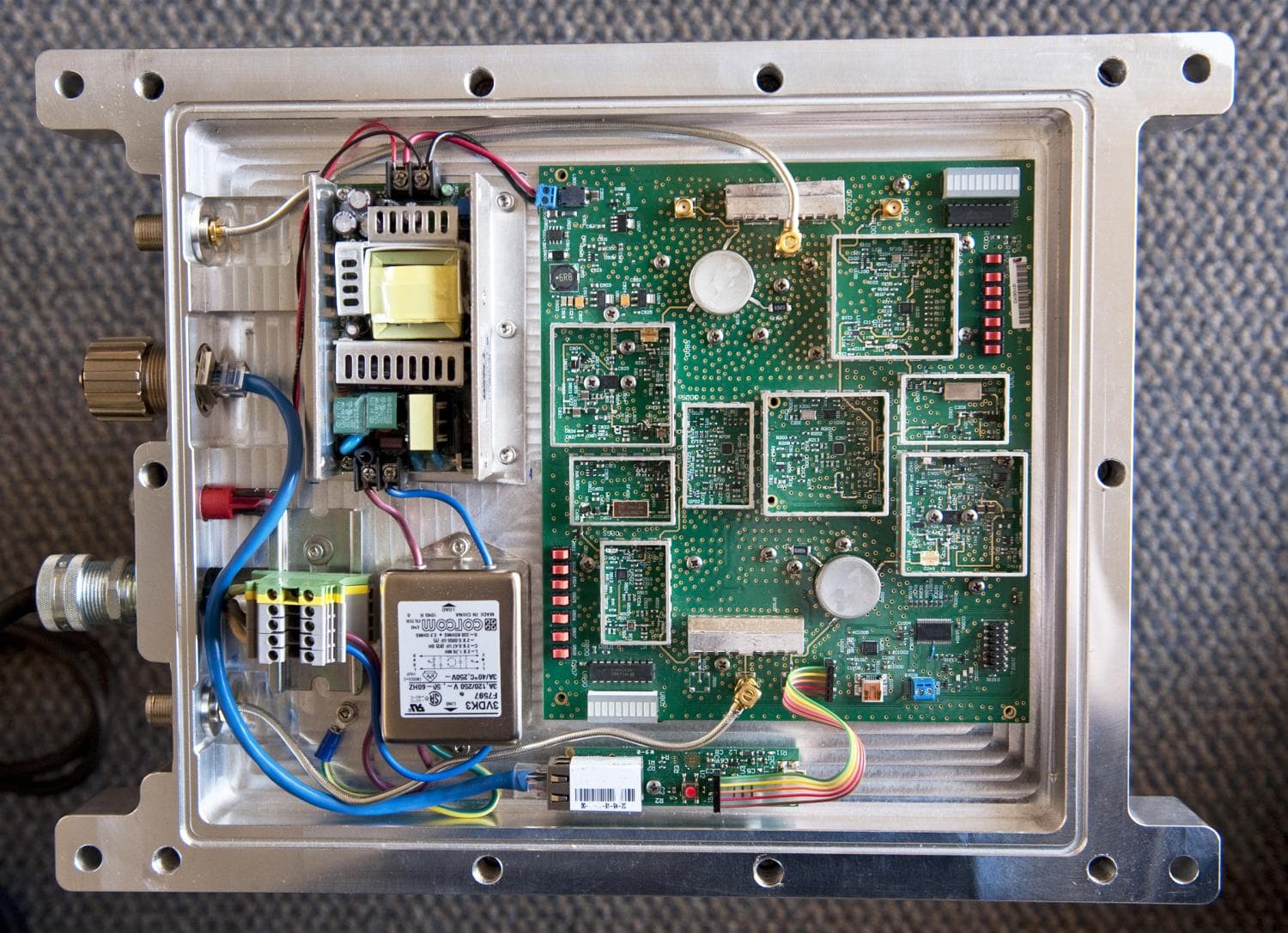
UDIRBB850
Dec 12, 2013Repeater
Equipment Class
B2I - Part 20 Industrial Booster (CMRS)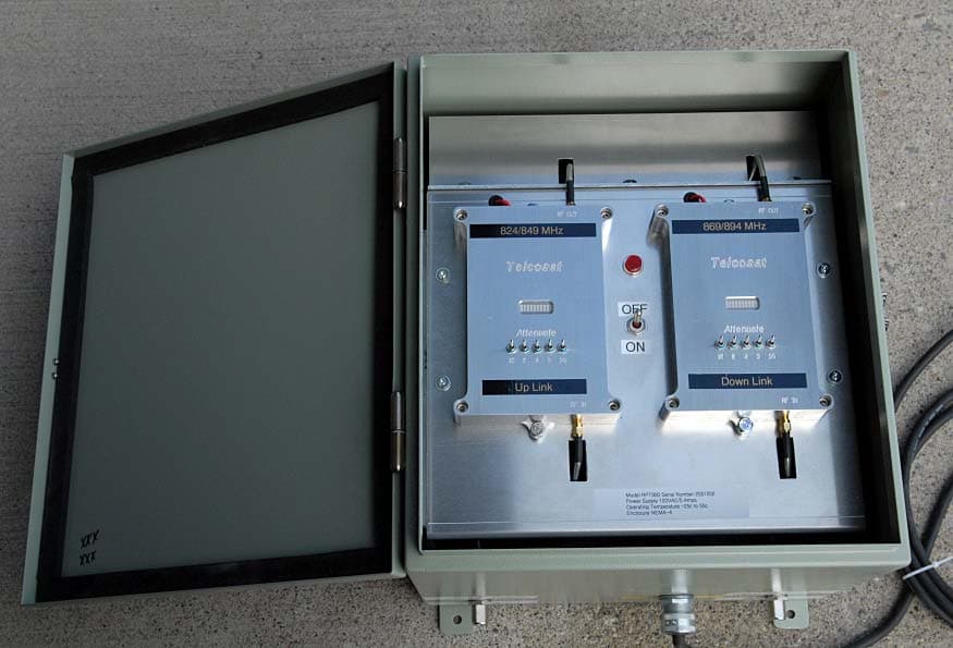
UDIRPT900
Sep 02, 2006Repeater
Equipment Class
TNB - Licensed Non-Broadcast Station Transmitter