UDIRPT900Repeater
Telcosat Inc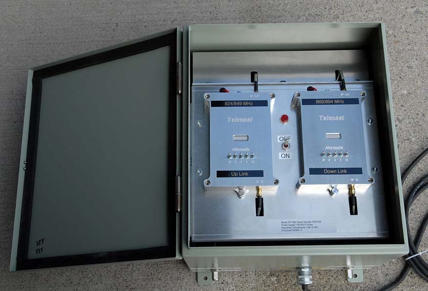
Click to zoom
Application Details
- Equipment Class
- TNB - Licensed Non-Broadcast Station Transmitter
- Date of Grant
- Sep 02, 2006
- Application Purpose
- Original Equipment
- Date of Application
- Aug 31, 2006
- Equipment Note
- Repeater
- Frequency Range
- 869.00000000 - 894.00000000
- Company
- Telcosat Inc
- Country
- Canada
Documents & Files
Document Text
Text extracted from the exhibit documents filed with the FCC. Open a document above to read the original.
Users Manual
OPERATION & MAINTENANCE MANUAL CELLULAR CDMA/GSM REPEATER MODEL RPT 900 Document Release Date: August 30th 2006 Author: Carl Bosnyak Document use is restricted to that described on the cover 1 Any modifications to this device will void FCC and IC approvals. Document use is restricted to that described on the cover 2 Manual Number: TELCOSAT RPT 900 April 2006 TELCOSAT INC OPERATIONS & MAINTENANCE MANUAL CELLULAR REPEATER MODEL RPT 900 TELCOSAT RPT 900 Model RPT 900U UPLINK Model RPT 900D DOWNLINK The information set forth in this document and all rights in and to inventions disclosed herein, and patents which might be granted thereon disclosing, employing or covering the materials, methods, techniques or apparatus described herein are the exclusive property of Telcosat Inc. This document is an operation and maintenance manual. No disclosure or reproduction of the information or drawings shall be made of any other purpose without the prior written consent of Telcosat Inc. Use of the information contained herein to fabricate or assemble any item in whole or in part is expressly prohibited. Any modifications to this device will void FCC and IC approvals. A Canadian Company 116, 1919 – 27 th Ave NE, Calgary, Alberta, Canada. T2E 7E4 TEL (403) 291-4031 FAX (403) 291-3059 Document use is restricted to that described on cover TELCOSAT RPT 900 SAFETY SUMMARY High voltage is used in the operation of this equipment. Death on contact may result if personnel fail to observe the following safety precautions: • Only qualified trained personnel can install this equipment. Electrical connection and installation must meet your local Electrical Safety Installation codes. • Prior to any maintenance or inspection of this device disconnect the power supply. • Do not remove covers or access plates on the equipment unless you are a trained technician and authorized to carry adjustment and maintenance for this apparatus. • When installing antennas always be aware of high voltage overhead power lines. Contact with power lines will result in severe injury and or death. • To prevent electrical shock or damage to the equipment, do not operate the repeater until you thoroughly understand the operation and function of all controls, indicators, and connectors. • The RPT900 Repeater weighs approximately 45 lbs/ 22kilograms. The repeater must be attached to the appropriate supporting device using the welded supporting lugs on the enclosure. The nuts and bolts must be a minimum Grade 5, ¼” (6mm) diameter and corrosion resistant. FIRST AID In case of electrical shock: THIS PERSON COULD STILL BE IN CONTACT WITH ELECTRICAL POWER. DO NOT TOUCH THIS PERSON BEFORE YOU INSULATE YOUR SELF FROM THE ELECTRICAL SOURCE. • Turn off the electrical power. • If you cannot turn off the electrical power, pull, push, or lift the person to safety using a dry wooden pole, a dry rope, or some other insulating material. Do not use any metallic objects to move this person. • After the injured person is no longer in contact with the electrical source, obtain/perform immediate medical attention. Document use is restricted to that described on cover 4 TELCOSAT RPT 900 TABLE OF CONTENTS TABLE OF CONTENTS SAFETY SUMMARY-----------------------------------------------------------------------------------------------------------Page 4 FIRST AID------------------------------------------------------------------------------------------------------------------------Page 4 TABLE OF CONTENTS--------------------------------------------------------------------------------------------------------Page 5 CHAPTER 1 1.1 GENERAL Page 6 1.2 INTRODUCTION Page 6 1.2.1. MATERIALS Page 6 1.2.2 RPT 900 APPLICATIONS Page 6 1.3 RPT 900 SPECIFICATIONS Page 7 1.4 TECHNICAL ASSISTANCE Page 7 OPERATIONAL OVERVIEW CHAPTER 2 Page 8 2.1 GENERAL Page 8 2.2 REPEATER MODULE RF PATHS Page 8 2.3 DETAILED TECHNICAL RF SIGNAL PROCESSES Page 9 2.4 AC POWER DISTRIBUTION Page 10 INSTALLATION CHAPTER 3 3.1 WARNING Page 10 3.2 TOOLS REQUIRED Page 10 3.3 ANTENNA REQUIREMENTS Page 11 3.4 ANTENNA ISOLATION & COAX CABLES Page 12 3.5. INSTALLING YOUR REPEATER Page 13 3.6 POWER AND ATTENUATOR SWITCH SETTINGS Page 14 3.7 RSSI INDICATOR AND SIGNAL LEVELS Page 14 3.8 ALIGNING YOUR ANTENNA Page 14 3.9 ADJUSTING UPLINK POWER Page 15 WARRANTY REPAIR CHAPTER 4 Page 16 4.1 WARRANTY Page 16 4.2 LIMITED WARRANTY Page 16 EQUIPMENT STORAGE CHAPTER 5 Page 17 APPENDIX A TECHNICAL SPECIFICATIONS TABLE ONE Page 18 APPENDIX A RF EXPOSURE LEVELS Page 19 APPENDIX B RETURN GOODS PROCEDURE Page 20 B2. Returned Goods Procedure Page 20 B3. Shipping Procedure Page 20 B4. Returned Shipments Page 20 B5. Repair / Return Status Page 20 LIST OF FIGURES Figure 1-1 RPT 900 in a typical repeater remote site set up configuration Page 7 Figure 2-1 RPT 900 UP and DOWNCONVERTER Blocks Page 9 LIST OF TABLES Document use is restricted to that described on cover 5 Table 1- Technical Specifications Page 19 TELCOSAT RPT 900 CHAPTER 1 SCOPE 1.1 GENERAL The TELCOSAT RPT 900 Cellular Repeater (consisting of UPLINK and DOWNLINK bidirectional system) contains operational and maintenance information. This manual consists of four chapters and two appendices as follows: • Chapter 1 outlines the manual contents, with description and general application notes • Chapter 2 contains an operational overview and tune-up procedures (single and multi carrier). • Chapter 3 contains installation procedures, packing and shipping instructions. • Chapter 4 contains the repeater warranty information • Appendix A contains unit specifications and environmental data. • Appendix B contains the return goods procedure. 1.2 INTRODUCTION The TELCOSAT RPT 900 is a bidirectional system consisting of UPLINK and a DOWNLINK modules used in locations requiring coverage, where conventional communication systems cannot reach, such as buildings, parking structures, tunnels and remote areas. The TELCOSAT RPT 900 is designed to provide coverage by using reliable, high intercept com…
Text truncated - open the document above for the full version.
Cover Letter(s)
NATIONAL TECHNICAL SYSTEMS, INC. www.ntscorp.com 5151 47 th Street NE • Calgary, Alberta T2E 3R2 (403)295-5134 • • (403) 295-4190 fax June 21, 2006 American Telecommunications Certification Body, Inc. 6731 Whittier Avenue Suite C110 McLean, VA 22101 RE: Certification Application FCC ID: UDIRPT900 IC #: 5842A-RPT900 Please be advised pursuant to 47CFR 0.459 that the following information is to be held permanently confidential on behalf of Telcosat Inc • Schematics • Block Diagram • Operational description This application contains technical information that Telcosat Inc deems to be trade secrets and proprietary. If made public, the information might be used to the disadvantage of the applicant in the marketplace. Thank you for your attention to this matter. Sincerely, Glen Moore EMC Manager NTS On Behalf of Telcosat Inc
Cover Letter(s)
Tim, Please find enclosed the responses to all of the issues on the UDIRPT900 submission. Please call me if you have any questions or concerns Thank you Glen Moore 1) It is not clear if this device fully demodulates and then remodulates only a recognized signal. This is being submitted for CDMA, but it is unsure how this device behave in the presence of TDMA/GSM, etc. signals as well. Please explain. Additionally, please note that currently only CDMA appears to be covered by testing. For other modulations testing must have been performed if intended to be used for these modulations (conducted spurious, intermodulation, input/output bandwidth). Please review FCC amplifier/booster guidance attached for complete information. NOTE: One test report suggests TDMA as well. Response: The RPT900 device does not demodulate or re-modulate an incoming signal. It is fundamentally a bi- directional amplifier (signal booster) although it is constructed around the heterodyne principal. The unit comprises of saw filters and cavity filters. The incoming signals are only down converted to an IF level frequency of 70 megahertz and band width limited to 25 megahertz by a SAW filter. Note, no alteration to the signal occurs anywhere in the system. This device is to be certified for CDMA signals, not TDMA This device is not a receiver, only a linear bi-directional amplifier. This device does not de-modulate or re-modulate signals. 2) Please provide a Tune up procedure over the power range provided (2.1033(c)(9)). Response: No tune up procedure is required for this device 3) Please provide a parts list for this device. As a minimum this must include the active components in the RF circuitry. Response: All parts and component designations are clearly indicated on the schematics which has always been accepted in the past 4) If necessary, please update the confidentiality to include the parts list and tune up procedures provided. Response: Not applicable, components are clearly indicated on schematics, and no tune up is required 5) Per FCC guidelines for repeaters and boosters, please justify the input drive level used (why was the level selected, was it the maximum input rating and maximum gain set and then used for all tests). Response: The input drive level of -65dBm is the optimal maximum input level with maximum gain set of 95dB. This maximum input level was used through out all the tests. The combination if maximum input level and maximum gain level of 95dB will provide a rated power output of 1 watt. 6) Please confirm testing was done as maximum output levels the device is cable of. Response: The device was tested at maximum power levels at all times. From: [email protected] To: [email protected] Cc: [email protected] Subject: ATCB Response Page 1 of 4In 7/11/2006Printed for "Timothy R. Johnson" <[email protected]> 7) This device appears to be being approved for 1 W output power. However users manual page 19 suggests +39 dBm. Please review/explain/correct as necessary. Response: Page 19 on the user manual has been changed to +30dBm 8) While the Telcosat report does appear to shown various occupied bandwidth outputs, this does not appear to be compared to the inputs (i.e. both input and output occupied bandwidths measured and shown) per the FCC guidance on amplifers, repeaters, and boosters. Please see attachment. Response: Please refer to page 9. The test up for the repeater shows an actual screen shot of a CDMA input signal, and also showing the resulting CDMA out-put signal. 9) Test report should support compliance by comparing results obtained to limits, either by providing limit lines on the plots or a separate tables which compare measurements against the limits. Telcosat report should be updated for this. Response: To comply we have inserted limit lines on page 8. 10) Generally spurious emissions (conducted and radiated) should start at the lower of 9 kHz or lowest frequency generated within the device (including IF, TXCO, etc). Currently conducted spurious appears to only start at 820 MHz only (single channel test) although there are additional plots at the back of the Telcosat report. Additionally these results should utilize 100 kHz as specified by Part 22. Please correct. Response: Please refer to page 16. The device was re-measured using 100KHz RBW. Document has been updated. 11) It is uncertain if proper modulation was used for single channel test for conducted spurious emissions. Please review. Response: Report has been updated with correct test data 12) The two tone method appears to only support compliance in the passband. 2.1057 should be followed to support compliance below and above the passband for spurious emissions and also using a 100 kHz RBW as specified by 22.917. Response: Report has been updated with correct data 13) Please explain power output results. For instance, 2 tones show a composite power of 1 Watt output. Is the output one watt for single or multiple carriers. Please explain. Response: Maximum power out-put is 1 watt for this device. If there are two carriers then it is two carriers at +27dBm (equivalent to 1 watt composite power) 14) It is uncertain if the power results were taken using CW signals or proper modulation. FCC requires proper modulation present. Response: Report updated and uploaded 15) FCC requires applicant to understand their responsibilities under Sections 22.383 for related booster/inbuilding operations. Please confirm applicant understands their responsibilities under this section of the rules. Response: We have a copy of the rules pertaining to sec 22.383. Related to booster in building operations. We fully understand the rules and the responsibilities. 16) Duty cycle in test report (NTS) appears to define a duty cycle of 1%. Please explain as these device are considered to be capable of much more. Response: This was a type error in the report and has been corrected to 100% Page 2 of 4In 7/11/2006Printed for "Timothy R. John…
Text truncated - open the document above for the full version.
External Photos
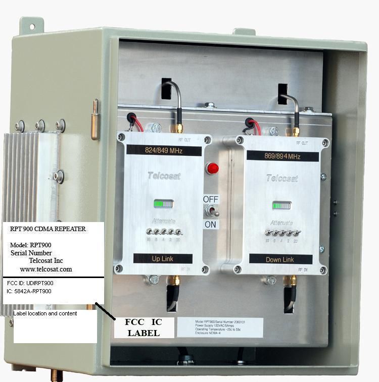
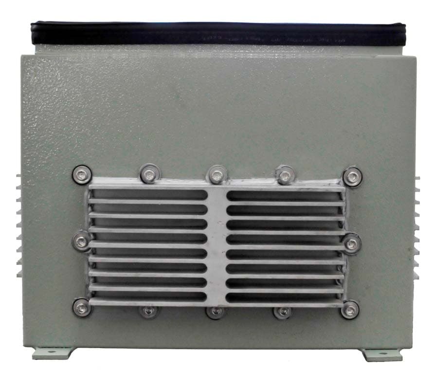
FCC ID: UDIRPT900 CG-316 IC: 5842A-RPT900 Telcosat Inc External Photograph Exhibit RPT900 Cover Off Bottom Side of Enclosure FCC ID: UDIRPT900 CG-316 IC: 5842A-RPT900 Telcosat Inc Right Side of enclosure Left Side of Enclosure
Internal Photos
FCC ID: UDIRPT900 CG-316 IC: 5842A-RPT900 Telcosat Inc Internal Photograph Exhibit RPT900 Cover Off Uplink Board Component Side FCC ID: UDIRPT900 CG-316 IC: 5842A-RPT900 Telcosat Inc Downlink/Uplink Board – Bottom side Downlink Board Component Side FCC ID: UDIRPT900 CG-316 IC: 5842A-RPT900 Telcosat Inc Power amplifier enclosure RF Power Amplifier Board FCC ID: UDIRPT900 CG-316 IC: 5842A-RPT900 Telcosat Inc Controller Board – Top Side Controller Board Bottom side
Parts List/Tune Up Info
2) Please provide a Tune up procedure over the power range provided (2.1033(c)(9)). Response: No tune up procedure is required for this device 3) Please provide a parts list for this device. As a minimum this must include the active components in the RF circuitry. Response: All parts and component designations are clearly indicated on the schematics which has always been accepted in the past Page 1 of [email protected], 10:41 AM 7/10/2006 -0700, ATCB Response 9/1/2006Printed for "Timothy R. Johnson" <[email protected]>
RF Exposure Info
FCC ID: UDIRPT900 CG-316 IC: 5842A-RPT900 Telcosat Inc RF Exposure MPE Exhibit Maximum permissible exposure is Freq. (MHz)/1500 = MPE mW/cm 2 869 MHz/1500 = 0.5793 mw/cm 2 The following calculations determine at what distance from the antenna the power density is = 0.5793 mw/cm 2 Tx output power = 30.4 dBm (based on GSM power measurement) Antenna Gain = 14.6 dBi EIRP of TX and Antenna = 45 dBm 45 dBm= 28.8 Watts or 28840 mW MPE Calculation 2 2 4 )mW/cm( d EIRP PdtyPowerDensi π == Pd EIRP d π4 = 2/5793.04 8.31622 cmmw d π = d = 65.9 cm The minimum safe distance is 65.9 cm for the Telcosat RPT900 antenna when installed. This is the worst case for both the uplink and downlink. The maximum antenna gain stated is for both uplink and downlink. This product is installed by trained professionals in outdoor applications only
Test Report
CDMA POWER PLOT Page 34. depicts a power plot of a single CDMA modulated Carrier showing the rated power out put measured at the output terminals of the RPT900 For multi-carrier operation additional back off is applied at the time of systems integration into the network to accommodate the number of carriers present at a given site. This is accomplished by using the digital attenuators in the IF of the unit by using the toggle switches provided on the uplink / downlink modules. Additionally the Pin Diode limiting diode in the IF will gently start limiting 10dB below the +30dBm output level, reaching full limiting power at full power output, thus preventing exceeding rated power output. UPLINK 824 / 849 Megahertz CDMA Modulated Carrier showing Peak Power measurement. CDMA Power Pot single modulated carrier. Input signal from CDMA signal generator -74dBm Out-put from RPT 900 30.36dBm Peak Power Measurements using Agilent spectrum analyzer CDMA POWER PLOT Page 35. depicts a power plot of a single CDMA modulated Carrier showing the rated power out put measured at the output terminals of the RPT900 For multi-carrier operation additional back off is applied at the time of systems integration into the network to accommodate the number of carriers present at a given site. This is accomplished by using the digital attenuators in the IF of the unit by using the toggle switches provided on the uplink / downlink modules. Additionally the Pin Diode limiting diode in the IF will gently start limiting 10dB below the +30dBm output level reaching full limiting power at full power output, thus preventing exceeding rated power output. DOWN LINK 869 / 894 Megahertz CDMA Modulated Carrier showing Peak Power measurement. CDMA Power Pot single modulated carrier. Input signal from CDMA signal generator -74dBm Out-put from RPT 900 =29.52 dBm Peak Power Measurements using Agilent spectrum analyzer GSM POWER PLOT Page 36. depicts a power plot of a single GSM modulated Carrier showing the rated power out put measured at the output terminals of the RPT900 For multi-carrier operation additional back off is applied at the time of systems integration into the network to accommodate the number of carriers present at a given site. This is accomplished by using the digital attenuators in the IF of the unit by using the toggle switches provided on the uplink / downlink modules. Additionally the Pin Diode limiting diode in the IF will gently start limiting 10dB below the +30dBm output level, reaching full limiting power at full power output, thus preventing exceeding rated power output. DOWN LINK 869 / 894 Megahertz GSM Modulated Carrier showing Peak Power measurement. GSM Power Pot single modulated carrier. Input signal from GSM signal generator -66.7dBm Out-put from RPT 900 =30.41 dBm Peak Power Measurements using Agilent spectrum analyzer. GSM POWER PLOT Page 37. depicts a power plot of a single GSM modulated Carrier showing the rated power out put measured at the output terminals of the RPT900 For multi-carrier operation additional back off is applied at the time of systems integration into the network to accommodate the number of carriers present at a given site. This is accomplished by using the digital attenuators in the IF of the unit by using the toggle switches provided on the uplink / downlink modules. Additionally the Pin Diode limiting diode in the IF will gently start limiting 10dB below the +30dBm output level, reaching full limiting power at full power output, thus preventing exceeding rated power output. DOWN LINK 869 / 894 Megahertz GSM Modulated Carrier showing Peak Power measurement. GSM Power Pot single modulated carrier. Input signal from GSM signal generator -66.7dBm Out-put from RPT 900 =30.35 dBm Peak Power Measurements using Agilent spectrum analyzer.
Test Report
Telcosat Inc FCC: Part 2.1033 Author: Carl Bosnyak RF Engineering: Hellmut Frauscher P. ENG. Release date: July 27 th 2006 Tests performed in accordance to good engineering practices. 1 Test Voltages used. Module test voltage supplied by the internal power supply unit of the repeater RPT900 PA Power supply details. Current load 1.54 Amps@28volts DC maximum Make, Puls, Model ML30.102 Input voltage AC 100-240V (Wide Range), 47...63 Hz Admissible limits: AC 85...264V (DC 85...375V) Input current <0.6A (@ AC 100V, 30W Pout) <0.25A (@ AC 240V, 30W Pout) External fusing not required, unit provides internal fuse (T3A15H, not accessible) Transient immunity Transient resistance acc. to VDE 0160 / W2 Output voltage DC 10-12V (set to 10 volts) (adj. by front panel potentiometer, adj. range guaranteed); with jumper: 12V ±0.5%, without jumper: 10V ±0.5% Voltage regulation stat. <1% @ Vout = 10V stat. <1.2% @ Vout = 12V, dyn. ±2.5% Vout over all Ripple Noise (Spikes) <2mVPP (200kHz bandwidth., 50 Ω measurement.) <10mVPP (20MHz bandwidth., 50 Ω measurement.) Over-voltage protection. (OVP) <18V Rated continuous loading at convection cooling: max. Iout = 3A @ Vout = 10V, max. Iout = 2.5A @ Vout = 12V, • power reserve 25%–40% (depending on Vin); Overload behaviour Straight V/I characteristic (depending on Vin); Protection Unit is protected against (also permanent) short-circuit, overload and open-circuit. Certification Approvals The PSU complies with all major safety approvals for EU (EN 60950, EN 60204-1, EN 50178), USA (UL 60950, E137006, UL508 LISTED, E198865), Canada (CAN/CSA-C22.2 No 60950 [CUR],CAN/CSA-C22.2 No. 14 [CUL]), CB Scheme (IEC 60950). NEC Class 2 Power Supply and Hazardous Location Class I Div. 2 (UL 1604) Tests performed in accordance to good engineering practices. 2 Test Voltages used. PA test voltage supplied by the internal power supply unit of the repeater RPT900 PA Power supply details. Current load 1.5 Amps@10volts DC maximum Make, Puls, Model ML70.00 Input voltage AC 100-120/220-240V (switchable), 47...63Hz (AC 85...132V / AC 184...264V, DC 220...375V) Input current <1.6A (@ AC 100V, 72W Pout) <0.8A (@ AC 220V, 72W Pout) External fusing Not required, unit provides internal fuse (T3A15H, not accessible) Output voltage Voltage set to 28 volts DC DC 24-28V adj. by front panel potentiometer; 24.5V ±0.5% at rated load Voltage regulation stat. <1% Vout dyn. < ±2% Vout over all Ripple/Noise <50mVPP (20MHz bandwidth., 50 Ω measurement.) Over-voltage protection. (OVP) <40V Rated continuous loading up to 3A @ 24V /2.6A @ 28V (convection cooling) Overload behaviour PULS Overload Design™: No switch-off at overload/short-circuit, instead: up to 1.5 · Irated. So you need no oversizing to start awkward loads. Protection Unit is protected against (also permanent) short circuit, overload and open-circuit. Certification Approvals The PSU complies with all major safety approvals for EU (EN 60 950, EN 60204-1, EN 50178), USA (UL 60950, UL508 LISTED), Canada (CAN/CSA-C22.2 No 60950 [CUR], CAN/CSA-C22.2 No. 14 [CUL]), CB Scheme (IEC 60950). NEC Class 2 Power Supply Tests performed in accordance to good engineering practices. 3 DC voltage of Power Amplifier (PA) 28.5 DC volts Current level of PA 770 Milliamps Power output of PA "+30dBm Composite two tones Input power into the Repeater "-68dBm composite at maximum gain setting of 95dB Output power can be adjusted from 0.0dBm to +30dBm internally only, depending on the required application. HP Agilent Radar RF pin diodes (Limiter Diodes) protect the receiver front end and IF stages from strong pulsed signal causing saturation. Carefully adjusted antenna systems in terms of Antenna Isolation and signal levels are required so the system cannot operate in a saturation mode. FCC: Part 2.1051 Spurious Emissions and I.M.D. TWO TONE TEST SET-UP CDMA/TDMA/GSM Input level two tones at -68dBm each, for rated power output 2 tones of +27dBm each. All tests taken at +20 degrees Celsius. Tests performed in accordance to good engineering practices. 4 Spectrum analyzer screen shot of the downlink pass band, in-band and immediately adjacent. Transmit Power 1 watt (P) = 43+10log(P)= Screen Shot displaying Two Tones in the Middle of the Down-Link Pass-band Typical IMD=> 50dBc @ Rated Power out-put (30dBm Composite) In-put Signals to splitter, -65dBm + (-3dBm Splitter) to Repeater = 95dBm Gain Spectrum analyzer shot of the down-link pass band. Tests performed in accordance to good engineering practices. 5 Down-link lower edge of band pass Down-link upper edge of band pass Tests performed in accordance to good engineering practices. 6 Up-link lower edge of band pass Up-link upper edge of band pass Plot displaying greater intermodulation products at the enhancer out-put terminals equal to - 44.35dBW Tests performed in accordance to good engineering practices. 7 Third Order I.MD. Performance measured with Vector Network Analyzer Anritsu model number VNA MS4623B 6 Gigahertz. Serial number 031601, Calibrated September 2005 Spectrum Harmonics to 6 GHz Conducted. Measurements Performed with Vector Network Analyzer Anritsu model number VNA MS462 at rated power output Agilent Spectrum Analyzer model E4404B 6 Gigahertz. Serial number 031601 Third order I.M.D. measurement from the repeater RPT900 reference to +30 dBm rated composite output power Tests performed in accordance to good engineering practices. 8 CDMA Performace. Test Set-up for Repeater RPT900 Measuring CDMA Carrier Screen Shots From Agilent E4404B (9kHz - 6.7 GHz) Spectrum Analyzer Tests performed in accordance to good engineering practices. 9 Spectrum analyzer screen shot of a 2000 CDMA ISO95 Spreading SR1 at the lower band edge of the Down Link pass band (869 MHz to 894 MHz) Spectrum analyzer screen shot of a 2000 CDMA ISO95 Spreading SR1 at the center of the Down Link pass band. (869 MHz to 894 MHz) Spectrum analyzer screen shot of a 2000 CDMA ISO95 Spreading SR1of the upper edge of the Down Link pass band. (869 MHz to …
Text truncated - open the document above for the full version.
Test Report
Confidentiality Statement: This report and the information contained herein represent the results of testing articles/products identified and selected by the client. The tests were performed to specifications and/or procedures approved by the client. National Technical Systems (“NTS”) makes no representations expressed or implied that such testing fully demonstrates efficiency, performance, reliability, or any other characteristic of the articles being tested, or similar products. This report should not be relied upon as an endorsement or certification by NTS of the equipment tested, nor does it represent any statement whatsoever as to its merchantability or fitness of the test article or similar products for a particular purpose. This document shall not be reproduced except in full without written approval from National Technical Systems (“NTS”) and the customer. Product Integrity Laboratory 5151-47 th Street, NE Calgary, Alberta T3J 3R2 Tel: (403) 568-6605 Fax : (403) 568-6970 Certification Test Report CFR 47 FCC Part 22 Industry Canada RSS 131 Emissions and Frequency Stability only for Telcosat FCC ID # UBLSIU3A IC ID#: 6548A-SIU3A Project Code CG-316 (Report CG-316-RA-1-0) Revision: 1 June 16, 2006 Prepared for: Telcosat Author: Glen Moore EMC Manager Approved by: Nick Kobrosly Lab Manager CG-316-RA-1-1 Telcosat Inc Compliance Test Report FCC ID # UDIRPT900 IC ID#: 5842A-RPT900 The test results contained in this report refer exclusively to the product(s) presented for testing. The test results do not cover models or products not referred herein. This test report should not be published or duplicated in whole or part without permission from the testing body and the customer. NTS Product Integrity Laboratory, 5151-47 th Street N.E. Tel: 403-568-6605, Fax: 403-568-6970 Confidential 2 of 28 7/6/2006 Report Summary NTS Canada Product Integrity Laboratory 5151-47 th Street, N.E. Calgary Alberta T3J 3R2 Accreditation Numbers: FCC 101386 IC 46405-3978 File # IC3978-2 Standards Council of Canada Accredited Laboratory No. 440 Applicant: Telcosat Inc 116, 1919 – 27 th Avenue NE Calgary, AB T2E 7A4 Tel:403-291-4031 Email: [email protected] Customer Representative: Carl Bosnyak EUT Description: EUT Description Manufacturer Model Revision Serial Number Cellular Repeater Telcosat Inc RPT900 N/A 2060202 CG-316-RA-1-1 Telcosat Inc Compliance Test Report FCC ID # UDIRPT900 IC ID#: 5842A-RPT900 The test results contained in this report refer exclusively to the product(s) presented for testing. The test results do not cover models or products not referred herein. This test report should not be published or duplicated in whole or part without permission from the testing body and the customer. NTS Product Integrity Laboratory, 5151-47 th Street N.E. Tel: 403-568-6605, Fax: 403-568-6970 Confidential 3 of 28 7/6/2006 Test Summary Deviations* from: Appendix Test/Requirement Description Base Standard Test Basis NTS Procedure Pass / Fail Applicable Rule Parts A Radiated Spurious Emissons No No No PASS 2.1046/90.210e) B Powerline AC conducted emissions No No No PASS 2.1049/90.210e) C Frequency Stability No No No PASS RSS Gen section 4.3 Test Result: The product presented for testing complied with test requirements as shown above. Prepared By: ______________________ Glen Moore EMC Manager CG-316-RA-1-1 Telcosat Inc Compliance Test Report FCC ID # UDIRPT900 IC ID#: 5842A-RPT900 The test results contained in this report refer exclusively to the product(s) presented for testing. The test results do not cover models or products not referred herein. This test report should not be published or duplicated in whole or part without permission from the testing body and the customer. NTS Product Integrity Laboratory, 5151-47 th Street N.E. Tel: 403-568-6605, Fax: 403-568-6970 Confidential 4 of 28 7/6/2006 Table of Contents REPORT SUMMARY ........................................................................................................................................................2 TEST SUMMARY..............................................................................................................................................................3 REGISTER OF REVISIONS .............................................................................................................................................5 1.0 INTRODUCTION ................................................................................................................................................6 1.1 PURPOSE.................................................................................................................................................................................... 6 2.0 TEST EUT DESCRIPTION .................................................................................................................................6 2.1 CONFIGURATION.......................................................................................................................................................................... 6 2.1.1 EUT POWER................................................................................................................................................................................. 7 2.2 SUPPORT CABLES................…
Text truncated - open the document above for the full version.
Contact Information
Applicant
Carl Bosnyak(CEO)
Technical Contact
Non-Technical Contact
NTSJanet Johanntges
[email protected]403 568 6605
Test Firm
National Technical Systems (NTS)Nick Kobrosly
Technical Specifications
| # | Rule Parts | Frequency Range | Power Output | Emission | Tolerance |
|---|---|---|---|---|---|
| 4 | 22H | 869 MHz - 894 MHz | 900.00 mW | F9W | Amp |
Other Applications from Telcosat Inc
UDIRPT700
May 05, 2021Booster
Equipment Class
B2I - Part 20 Industrial Booster (CMRS)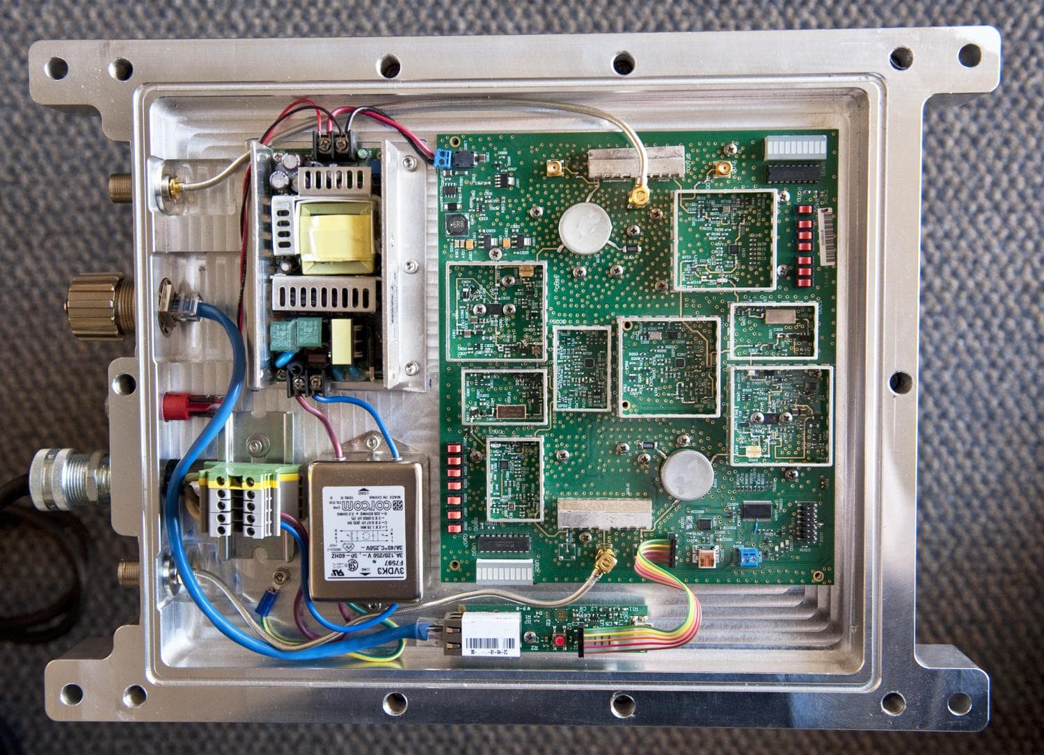
UDIRBB850
Dec 12, 2013Repeater
Equipment Class
B2I - Part 20 Industrial Booster (CMRS)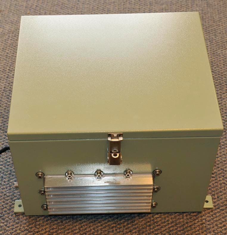
UDIRPT1900
Mar 22, 2010Repeater
Equipment Class
PCB - PCS Licensed Transmitter