FCCID.CO- FCC ID Database
HomeCompaniesEquipment ClassesSearch

© 2026 FCC ID Database. All rights reserved.

AboutContactData sourced from FCC public records
  1. Home/
  2. Continental Automotive Systems, Inc./
  3. UGB-UHI-5100

UGB-UHI-5100Bluetooth Handsfree Car Kit with HFP

Continental Automotive Systems, Inc.
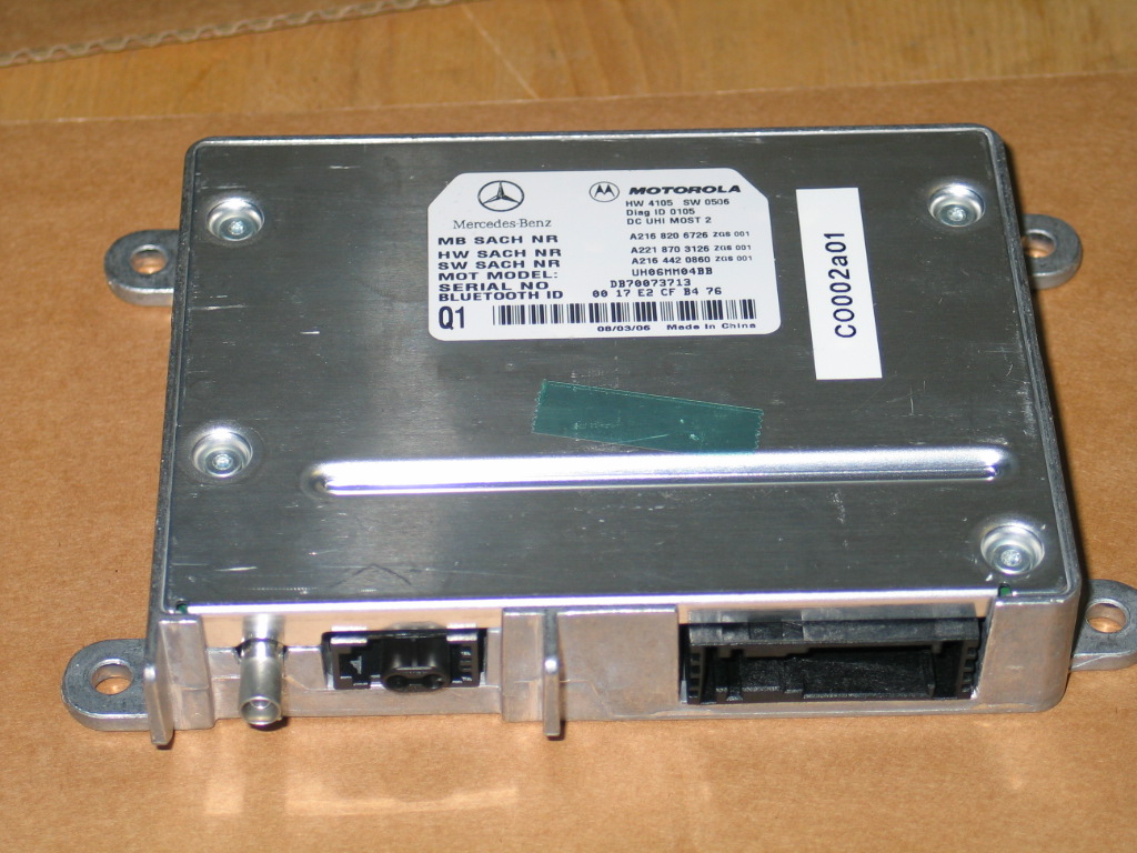
Bluetooth Handsfree Car Kit with HFP - FCC ID UGB-UHI-5100 - Continental Automotive Systems, Inc.
Click to zoom

Application Details

Equipment Class
DSS - Part 15 Spread Spectrum Transmitter
Date of Grant
Apr 10, 2007
Application Purpose
Original Equipment
Date of Application
Apr 10, 2007
Equipment Note
Bluetooth Handsfree Car Kit with HFP
Frequency Range
2402.00000000 - 2480.00000000
Company
Continental Automotive Systems, Inc.
Country
United States

Documents & Files

Select a file to view

Users Manual

↗

Cover Letter(s)

↗
↗

External Photos

↗

ID Label/Location Info

↗

Internal Photos

↗

Test Report

↗
↗

Test Setup Photos

↗

Document Text

Text extracted from the exhibit documents filed with the FCC. Open a document above to read the original.

Users Manual

83 Control systems COMAND operating safetyCOMAND introductionCOMAND FM/AM radioCOMAND satellite radio* (USA only)COMAND audio CD/audio DVD/MP3COMAND video DVD (USA only)COMAND telephone*COMAND navigationCOMAND address bookCOMAND system settingsCOMAND vehicle menuCOMAND automatic climate controlCOMAND seatsInstrument cluster control systemVoice Control* 84Control systemsCOMAND operating safety Warning! G Any alteration of elec tronic components or software can cause malfunctions.Radio, satellite radio* (USA only), amplifier, CD/DVD changer, navigation module, tele-phone and Voice Control Systems* are in-terconnected. Therefore, if one of the components is not operational, or has not been removed/ replaced properly, the func-tion of other components could be impaired.Such conditions might seriously impair the operating safety of your vehicle.We recommend to have any service work on electronic components carried out by an au-thorized Mercedes-Benz Center. Warning! G In order to avoid distraction which could lead to an accident, the driver should enter system settings while the vehicle is at a standstill, and operate the system only when permitted by road, weather and traffic conditions.Bear in mind that at a speed of just 30 mph (approximately 50 km/ h) , your car covers a distance of 44 feet (approximately 14 m) ev-ery second.COMAND supplies you with information to help you select your route more easily and guide you conveniently and safely to your destination. For safety reasons, we encour-age the driver to stop the vehicle in a safe place before answering or placing a call, or consulting the COMAND screen to read nav-igational maps, instruct ions, or downloaded information. Warning! G While the navigation system provides direc-tional assistance, the driver must remain fo-cused on safe driving behavior, especially attention to traffic and street signs, and should utilize the system’s audio cues while driving.The navigation system does not supply any information on stop signs, yield signs, traffic regulations or traffic safety rules. Their ob-servance always remain s in the driver’s per- sonal responsibility. DV D maps do not cover all areas nor all routes within an area. 85 Control systems COMAND introduction  COMAND introduction COMAND (C o ckpit M a n agement and D ata System) is an information and operating center for vehicle sound and communica-tions systems, including the radio and nav-igation system, as well as other optional equipment (satellite radio*, telephone*, etc.).Availability of functions while the vehi- cle is in motionFor safety reasons, certain COMAND func-tions are not available while the vehicle is in motion or they are only available to a limited extent. You will notice this, for ex-ample, by the fact that certain menu items cannot be selected or that the COMAND display shows a corresponding message. Switching COMAND on or off Press the o shortcut button in the center console (  page 86). COMAND calls up the menu last select-ed. COMAND componentsIn your vehicle, COMAND can be used to operate: audio functions  the navigation system  the telephone* and communication functions (SMS*)  Video DVD (USA only)  various vehicle settings COMAND consists of the following:  COMAND shortcut buttons  COMAND display  telephone* keypad  COMAND controller i When you switch off COMAND, you also switch off the currently playing audio source. During a telephone call, you cannot switch off COMAND. 86Control systemsCOMAND introductionCOMAND shortcut buttonsUse the COMAND shortcut buttons to se-lect main functions directly. Example:  Switching directly to Radio or CD menu: Press M once or twice. COMAND displayIn the COMAND display, you will find the function currently selected and the corre-sponding menus. The COMAND display is divided into several areas. 1 Status line 2 Main functions 3 Main area 4 Submenus 5 Climate control settings A white bar under the main functions 2 in- dicates the active area.Once you have selected a main function 2 , the main area 3 is active. i During Dynamic Rear View Monitor* opera- tion (  page 453) it is not possible to operate the COMAND shortcut buttons. Function Page 1 P Favorite button 240 2 M Shortcut button for:  CD/DVD  radio 120101 3 L Back button 94 4 O Seat menu 261 5 N Shortcut button for:  telephone*  navigation 132167 6 o COMAND on/off button 85 7 , Volume control 96 8 F Mute button 96 87 Control systems COMAND introduction Instrument cluste r multifunction displayThis section describes features and con-trols via the COMAND controller, display and shortcut buttons only.Please refer to the “Instrument cluster control system” section of this manual (  page 266) for function descriptions and operation of the inst rument cluster multi- function display and multifunction steering wheel buttons as they relate to COMAND features described in this section. Adjusting COMAND display illumination 1 Knob  Brightening illumination: Turn knob 1 clockwise.  Dimming illumination: Turn knob 1 counterclockwise. Swiveling COMAND display 1 Button for swiveling display to the left 2 Button for swiveling display to the right You can swivel the COMAND display to the left or right. The buttons are on the right-hand side of the instrument cluster. i The layout of the menus may vary depending on your vehicle’s equipment. This manual shows the menus for a fully equipped vehicle. 88Control systemsCOMAND introductionTelephone keypad*With the help of the telephone keypad, you can use your mobile phone if it is inserted in the cradle. 1 Telephone keypad 2 Folding cover COMAND controllerUse the COMAND controller to select menu functions shown on the COMAND display. 1 COMAND controller You can operate the COMAND controller as follows:  press briefly or press and hold  rotate to the left or right  slide to the left, right, up, down or diagonally In this way, you can move through the menus, select menu items or exit menus.You can move through the menus eithe…

Text truncated - open the document above for the full version.

External Photos

Test report Reference: 4_CONTI_0602_FCCb Page 31 of 54 Photo 2: EUT (top view ) Photo 3: EUT (bottom view) Test report Reference: 4_CONTI_0602_FCCb Page 32 of 54 Photo 4: EUT (connectors)

ID Label/Location Info

1 / Ulrich Schaefer / 27.07.2007 © Continental AG UHI-5100 Labelling UHI-BTIM Product labelling Bottom side: No label Top side: CONTINENTAL

Test Report

7 layers AG Aufsichtsratsvorsitzenderh Registergerichth registered in: Borsigstrasse 11 Chairman of the Supervisory Board: Düsseldorf, HRB 44096 40880 Ratingen, Germany Markus Becker USt-IdNr h VAT Nr: Phone: +49 (0) 2102 749 0 Vorstandh Board: DE 203159652 Fax: +49 (0) 2102 749 350 Dr. Hans-Jürgen Meckelburg www.7Layers.com René Schildknecht InterLab ® is a registered trademark of 7 layers AG FCC Measurement/Technical Report on Bluetooth ® transceiver UHI5100 Report Reference: 4_CONTI_0602_FCCb Test Laboratory: 7 layers AG Borsigstrasse 11 40880 Ratingen Germany email: [email protected] DAT-P-192/99-01 Note: The following test results relate only to the devices specified in this document. This report shall not be reproduced in parts without the written approval of the testing laboratory. Test report Reference: 4_CONTI_0602_FCCb Page 2 of 54 Table of Contents 0 Summary 3 0.1 Technical Report Summary 3 0.2 Measurement Summary 4 1 Administrative Data 6 1.1 Testing Laboratory 6 1.2 Project Data 6 1.3 Applicant Data 6 1.4 Manufacturer Data 6 2 Product labeling 7 2.1 FCC ID label 7 2.2 Location of the label on the EUT 7 3 Test object Data 8 3.1 General EUT Description 8 3.2 EUT Main components 9 3.3 Ancillary Equipment 9 3.4 EUT Setups 9 3.5 Operating Modes 9 4 Test Results 10 4.1 Occupied bandwidth 10 4.2 Peak power output 12 4.3 Spurious RF conducted emissions 14 4.4 Spurious radiated emissions 16 4.5 Band edge compliance 21 4.6 Dwell time 23 4.7 Channel separation 25 4.8 Number of hopping frequencies 26 5 Test Equipment 27 6 Photo Report 30 7 Setup Drawings 34 8 Annex measurement plots 35 8.1 Occupied bandwidth 35 8.2 Peak power output 38 8.3 Band edge compliance conducted and Spurious RF conducted emission41 8.4 Radiated emissions (f<30MHz) 48 8.5 Dwell time 50 8.6 Channel separation 53 8.7 Number of hopping frequencies 54 Test report Reference: 4_CONTI_0602_FCCb Page 3 of 54 0 Summary 0.1 Technical Report Summary Type of Authorization Certification for an Intentional Radiator (Frequency Hopping Spread Spectrum). Applicable FCC Rules Prepared in accordance with the requirements of FCC Rules and Regulations as listed in 47 CFR Ch.1 Parts 2 (10-1-05 Edition) and 15 (10-1-05 Edition). The following subparts are applicable to the results in this test report. Part 2, Subpart J - Equipment Authorization Procedures, Certification Part 15, Subpart C – Intentional Radiators § 15.201 Equipment authorization requirement § 15.207 Conducted limits § 15.209 Radiated emission limits; general requirements § 15.247 Operation within the bands 902-928 MHz, 2400-2483.5 MHz and 5725-5850 MHz Note: The tests were selected and performed with reference to the FCC Public Notice DA 00- 705, released March 30, 2000 Instead of applying ANSI C63.4-1992 which is referenced in the FCC Public Note, the newer ANSI C63.4-2003 is applied. Summary Test Results: The EUT complied with all performed tests as listed in chapter 0.2 Measurement Summary. Test report Reference: 4_CONTI_0602_FCCb Page 4 of 54 0.2 Measurement Summary FCC Part 15, Subpart C § 15.207 Conducted emissions (AC power line) The measurement was performed according to ANSI C63.4 2003 OP-Mode Setup Port Final Result op-mode 2 Setup_a01 AC Port (power line) N/A FCC Part 15, Subpart C § 15.247 (a) (1) Occupied bandwidth The measurement was performed according to FCC § 15.31 10-1-05 OP-Mode Setup Port Final Result op-mode 1 Setup_b01 Temp.ant.connector passed op-mode 2 Setup_b01 Temp.ant.connector passed op-mode 3 Setup_b01 Temp.ant.connector passed FCC Part 15, Subpart C § 15.247 (b) (1) Peak power output The measurement was performed according to FCC § 15.31 10-1-05 OP-Mode Setup Port Final Result op-mode 1 Setup_b01 Temp.ant.connector passed op-mode 2 Setup_b01 Temp.ant.connector passed op-mode 3 Setup_b01 Temp.ant.connector passed FCC Part 15, Subpart C § 15.247 (d) Spurious RF conducted emissions The measurement was performed according to FCC § 15.31 10-1-05 OP-Mode Setup Port Final Result op-mode 1 Setup_b01 Temp.ant.connector passed op-mode 2 Setup_b01 Temp.ant.connector passed op-mode 3 Setup_b01 Temp.ant.connector passed FCC Part 15, Subpart C § 15.247 (d), § 15.35 (b), § 15.209 Spurious radiated emissions The measurement was performed according to ANSI C63.4 2003 OP-Mode Setup Port Final Result op-mode 1 Setup_a01 Enclosure passed op-mode 2 Setup_a01 Enclosure passed op-mode 3 Setup_a01 Enclosure passed FCC Part 15, Subpart C § 15.247 (d) Band edge compliance The measurement was performed according to FCC § 15.31 (10-1-05) / ANSI C63.4 (2003) 10-1-05 / 2003 OP-Mode Setup Port Final Result op-mode 1 Setup_b01 Temp.ant.connector passed op-mode 3 Setup_b01 Temp.ant.connector passed op-mode 3 Setup_a01 Enclosure passed Test report Reference: 4_CONTI_0602_FCCb Page 6 of 54 1 Administrative Data 1.1 Testing Laboratory Company Name: 7 Layers AG Address Borsigstr. 11 40880 Ratingen Germany This facility has been fully described in a report submitted to the FCC and accepted under the registration number 96716 . The test facility is also accredited by the following accreditation organisation: - Deutscher Akkreditierungs Rat DAR-Registration no. DAT-P-192/99-01 Responsible for Accreditation Scope: Dipl.-Ing. Bernhard Retka Dipl.-Ing. Robert Machulec Dipl.-Ing. Thomas Hoell Report Template Version: 2006-05-09 1.2 Project Data Responsible for testing and report: Dipl.-Ing. Andreas Petz Date of Test(s): 2006-08-22 to 2006-08-30 Date of Report: 2006-09-11 1.3 Applicant Data Company Name: Temic Automotive of North America, Inc Address: 21440 West Lake Deer Park Illinois, 60010 Contact Person: Hassan Waheed Phone No.: +1 847 862 1749 Fax No.: +1 847 761 1674 1.4 Manufacturer Data Company Name: MOTOROLA IESS TIANJIN Address: NO.2 BOHAI ROAD Tianjin, 300457 P.R. China Contact Person: Bing Feng He Phone No.: + 86-22-25292482 Fax No.: + 86-22-25295990 Test report Reference: 4_CONTI_0602_FCCb Page 7 of 54 2 Product labeling 2.1 FCC ID label At the time of the report there was …

Text truncated - open the document above for the full version.

Test Setup Photos

Test report Reference: 4_CONTI_0602_FCCb Page 30 of 54 6 Photo Report Photo 1: Test setup for radiated measurements

Contact Information

Applicant

Jianming Zhang(Engineering Manager)
[email protected]+1 847 862 2435Fax: +1 847 761 8015

Technical Contact

Temic Automotive of North America, IncHassan Waheed
[email protected]+1 847 862 1749

21440 West Lake · Deer Park, Illinois, Illinois

Non-Technical Contact

Temic Automotive of North America, IncHassan Waheed
[email protected]+1 847 862 1749

Test Firm

7layers AGRobert Machulec
[email protected]49-2102-749-313Fax: 49-2102-749-350

Technical Specifications

#Rule PartsFrequency RangePower Output
115C2.40 GHz - 2.48 GHz1.20 mW
Confidentiality
Long Term
Grant Notes
Power listed is conducted. This device and its antenna(s) must not be co-located or operating in conjunction with any other antenna or transmitter.

Other Applications from Continental Automotive Systems, Inc.
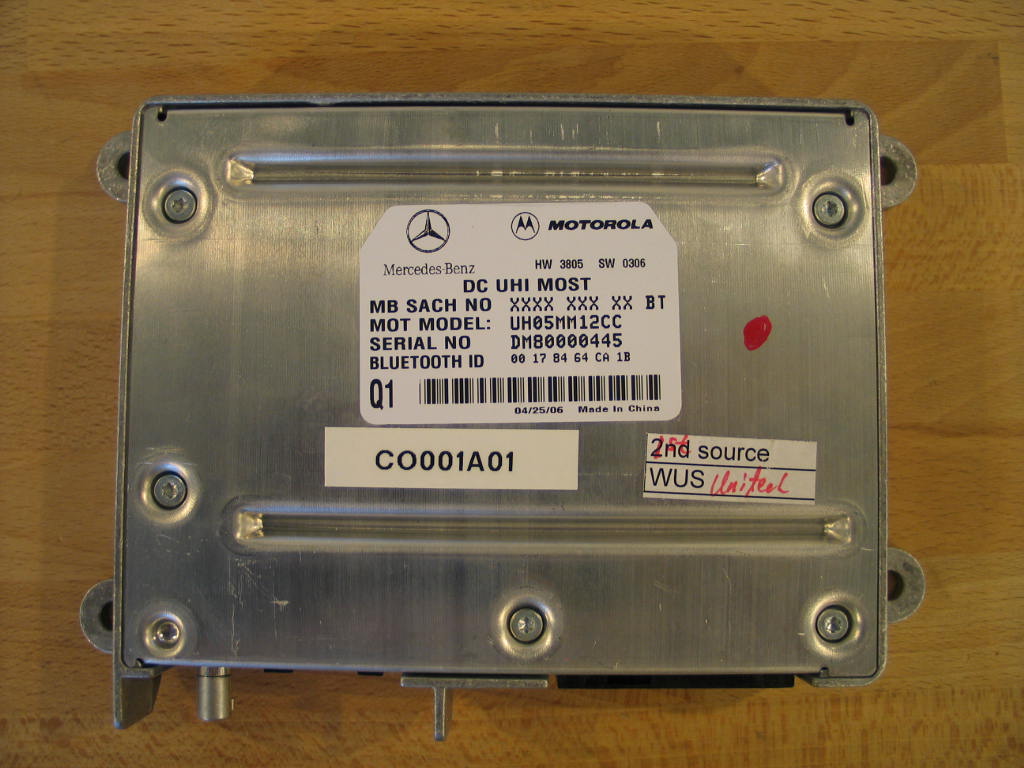
BT Handsfree Car Kit with HFP - FCC ID UGB-UHI-BTIM - Continental Automotive Systems, Inc.
UGB-UHI-BTIM

BT Handsfree Car Kit with HFP

Sep 12, 2006

Equipment Class

DSS - Part 15 Spread Spectrum Transmitter