FCCID.CO- FCC ID Database
HomeCompaniesEquipment ClassesSearch

© 2026 FCC ID Database. All rights reserved.

AboutContactData sourced from FCC public records
  1. Home/
  2. DRS Tactical Systems, Inc./
  3. UGLX10GX

UGLX10GXARMOR X10gx Rugged Tablet

DRS Tactical Systems, Inc.
ARMOR X10gx Rugged Tablet - FCC ID UGLX10GX - DRS Tactical Systems, Inc.
Click to zoom

Application Details

Equipment Class
DSS - Part 15 Spread Spectrum Transmitter
Date of Grant
Oct 07, 2010
Application Purpose
Original Equipment
Date of Application
Oct 07, 2010
Equipment Note
ARMOR X10gx Rugged Tablet
Frequency Range
2402.00000000 - 2480.00000000
Company
DRS Tactical Systems, Inc.
Country
United States

Documents & Files

Select a file to view

Users Manual

↗
↗
↗

Cover Letter(s)

↗
↗
↗
↗
↗

External Photos

↗
↗

ID Label/Location Info

↗
↗

Internal Photos

↗
↗

RF Exposure Info

↗
↗
↗

Test Report

↗
↗
↗
↗

Test Setup Photos

↗

Document Text

Text extracted from the exhibit documents filed with the FCC. Open a document above to read the original.

Users Manual

CastleNet BTC04R User Guide CastleNet Technology Inc. Copyright © 2008 All Rights Reserved. 1 of 6 User Guide Bluetooth2.1+EDR Module CastleNet BTC04R User Guide CastleNet Technology Inc. Copyright © 2008 All Rights Reserved. 2 of 6 Federal Communication Commission Interference Statement This equipment has been tested and found to comply with the limits for a Class B digital device, pursuant to Part 15 of the FCC Rules. These limits are designed to provide reasonable protection against harmful interference in a residential installation. This equipment generates, uses and can radiate radio frequency energy and, if not installed and used in accordance with the instructions, may cause harmful interference to radio communications. However, there is no guarantee that interference will not occur in a particular installation. If this equipment does cause harmful interference to radio or television reception, which can be determined by turning the equipment off and on, the user is encouraged to try to correct the interference by one of the following measures: - Reorient or relocate the receiving antenna. - Increase the separation between the equipment and receiver. - Connect the equipment into an outlet on a circuit different from that to which the receiver is connected. - Consult the dealer or an experienced radio/TV technician for help. This device complies with Part 15 of the FCC Rules. Operation is subject to the following two conditions: (1) This device may not cause harmful interference, and (2) this device must accept any interference received, including interference that may cause undesired operation. FCC Caution: Any changes or modifications not expressly approved by the party responsible for compliance could void the user's authority to operate this equipment. IMPORTANT NOTE: FCC Radiation Exposure Statement: This equipment complies with FCC radiation exposure limits set forth for an uncontrolled environment. To maintain compliance with FCC RF exposure compliance requirements, please follow operation instruction as documented in this manual. This transmitter must not be co-located or operating in conjunction with any other antenna or transmitter. CastleNet BTC04R User Guide CastleNet Technology Inc. Copyright © 2008 All Rights Reserved. 3 of 6 This device is intended only for OEM integrators under the following conditions: 1) The antenna must be installed such that 20 cm is maintained between the antenna. 2) The transmitter module may not be co-located with any other transmitter or antenna. As long as 2 conditions above are met, further transmitter test will not be required. However, the OEM integrator is still responsible for testing their end-product for any additional compliance requirements required with this module installed (for example, digital device emissions, PC peripheral requirements, etc.). IMPORTANT NOTE: In the event that these conditions can not be met (for example certain laptop configurations or co-location with another transmitter), then the FCC authorization is no longer considered valid and the FCC ID can not be used on the final product. In these circumstances, the OEM integrator will be responsible for re-evaluating the end product (including the transmitter) and obtaining a separate FCC authorization. End Product Labeling This transmitter module is authorized only for use in device where the antenna may be installed such that 20 cm may be maintained between the antenna and users. The final end product must be labeled in a visible area with the following: “Contains TX FCC ID: RK9-BTC04R”. Manual Information To the End User The OEM integrator has to be aware not to provide information to the end user regarding how to install or remove this RF module in the user’s manual of the end product which integrates this module. The users manual for OEM integrators must include the following information in a prominent location “IMPORTANT NOTE: To comply with FCC RF exposure compliance requirements. The antenna must not be co-located or operating in conjunction with any other antenna or transmitter. CastleNet BTC04R User Guide CastleNet Technology Inc. Copyright © 2008 All Rights Reserved. 4 of 6 Canada-Industry Canada (IC) Operation is subject to the following two conditions: this device may not cause interference and this device must accept any interference, including interference that may cause undesired operation of the device. IMPORTANT NOTE: IC Radiation Exposure Statement: This equipment with IC radiation exposure limits set forth for an uncontrolled environment. To maintain compliance with IC RF exposure compliance requirements, please follow operation instruction as documented in this manual. CastleNet BTC04R User Guide 1. INTRODUCTION The BTC04R series is a embedded Bluetooth module, smallest form factor for Notebook and handheld PC. The Bluetooth function is based on CSR BlueCore4-ROM A07 single chip, which is fully compliant with Bluetooth 2.1 specification plus EDR. It has good RF performance. Lowest power consumption, piconet and scatternet capability. The interface is HCI USB compliant with USB fully speed (12Mbits). The cable connection and PIN define of “Host I/F connector” from BT module (BTC04R series) to PC system is specially customized by OEM Laptop PC. There are two models shown as below: Model A: the chip antenna is embedded on board. Model B: it requires the external antenna connection. CastleNet Technology Inc. Copyright © 2008 All Rights Reserved. 5 of 6 CastleNet BTC04R User Guide 2. INSTALLATION 2.1 Installed in Laptop PC The Mainboard of the system should provide a Host connector and Cable connection for BT module. Please follow the SOP to install & assemble it step by step. 2.2 Testing in Lab The module is embedded inside Notebook. If for testing purpose, we provide the “USB Testing Board” in order to let tester connect BTC04R via the special cable connection to PC externally. The USB Testing Board provides +5V/3.3V conversion from PC Host. Plea…

Text truncated - open the document above for the full version.

Users Manual

MODEL X10gx TABLET COMPUTER USER’S GUIDE | REVISION B Copyright 2010, DRS Tactical Systems, Inc., Melbourne, Florida. All Rights Reserved. FRONT MATTER CONTENT PAGE 2 9711-26020-0001 Export Controlled – See Page 3 Rev B To learn more about ARMOR accessories, please call 1-888-872-1100 PORT REPLICATOR RF DOCK BATTERY CHARGER DESK DOCK BREAKOUT BOX VEHICLE POWER SUPPLY UNIVERSAL DOCK WITH KEYBOARD TRAY COMPACT KEYBOARD FRONT MATTER CONTENT PAGE 3 9711-26020-0001 Export Controlled – See Page 3 REV B MODEL X10 TABLET COMPUTER Trade Compliance Statement THIS DOCUMENT CONTAINS TECHNOLOGY CONTROLLED UNDER THE U.S. EXPORT ADMINISTRATION REGULATIONS (EAR) AND MAY NOT BE EXPORTED OR TRANSFERRED TO ANY FOREIGN PERSON, FOREIGN COUNTRY OR FOREIGN ENTITY, BY ANY MEANS, WITHOUT PRIOR WRITTEN APPROVAL FROM THE U.S. DEPARTMENT OF COMMERCE, BUREAU OF INDUSTRY AND SECURITY (BIS) AND DRS TECHNOLOGIES. THE INFORMATION DISCLOSED IN THIS DOCUMENT IS PROPRIETARY DATA OF DRS TACTICAL SYSTEMS, INC., AND MAY NOT BE REPRODUCED, USED, OR DISCLOSED WITHOUT THE PRIOR WRITTEN AUTHORIZATION OF DRS TACTICAL SYSTEMS, INC. DISTRIBUTION AUTHORIZED FOR USE PER DOCUMENT NUMBER 9120-02737-0100. VALIDATION REQUIRED FOR PLANNING, TESTING, INSPECTION, MANUFACTURING, PROCUREMENT AND QUOTES. Notice: • NOTE: This equipment has been tested and found to comply with the limits for a Class B digital device, pursuant to Part 15 of the FCC Rules. These limits are designed to provide reasonable protection against harmful interference in a residential installation. This equipment generates, uses and can radiate radio frequency energy and, if not installed and used in accordance with the instructions, may cause harmful interference to radio communications. However, there is no guarantee that interference will not occur in a particular installation. If this equipment does cause harmful interference to radio or television reception, which can be determined by turning the equipment off and on, the user is encouraged to try to correct the interference by one or more of the following measures: -- Reorient or relocate the receiving antenna. -- Increase the separation between the equipment and receiver. -- Connect the equipment into an outlet on a circuit different from that to which the receiver is connected. -- Consult the dealer or an experienced radio/TV technician for help. • This device complies with Part 15 of the FCC Rules. Operation is subject to the following two conditions: (1) this device may not cause harmful interference, and (2) this device must accept any interference received, including interference that may cause undesired operation. Changes not expressly approved by DRS Tactical Systems could void the user’s authority to operate the equipment. • For body-worn operation, this computer has been tested and meets the FCC RF exposure guidelines when used with ARMOR supplied accessories, or accessories designed specifically for this product. Use of other accessories may not ensure compliance with FCC RF exposure guidelines. • This X10gx tablet computer has been tested for compliance with ATEX directive 94/9/EC. • This Class B digital apparatus complies with Canadian ICES-003, Issue 4 June 7, 2004 and RSS-210, Issue No 7 (June 2007) and No 5 (Nov 2001). • Cet appariel numérique de la classe B est conforme à la norme NMB-003, No. 4, June 7, 2004; et CNR-210, No 7 (June 2007) et No 5 (Nov 2001). • [In Canada], this product is restricted to indoor use due to its operation in the 5.15 to 5.25-GHz frequency range. Industry Canada requires this product to be used indoors to reduce the potential for harmful interference to co-channel mobile satellite systems. FRONT MATTER CONTENT PAGE 4 9711-26020-0001 Export Controlled – See Page 3 Rev B • To prevent radio interference to the licensed service [in Canada], this device is intended to be operated indoors and away from windows to provide maximum shielding. Equipment (or its transmit antenna) that is installed outdoors is subject to licensing. • Pour empêcher que cet appareil cause du brouillage au service faisant l'objet d'une licence, il doit être utilisé a l'intérieur et devrait être placé loin des fenêtres afinde fournir un écran de blindage maximal. Si le matériel (ou son antenne d'émission) est installé à l'extérieur, il doit faire l'objet d'une licence. FRONT MATTER CONTENT PAGE 5 9711-26020-0001 Export Controlled – See Page 3 Rev B FRONT MATTER CONTENT PAGE 6 9711-26020-0001 Export Controlled – See Page 3 Rev B NOTICE DRS Tactical Systems, Inc. reserves the right to revise this publication or to change its contents without notice. Information contained herein is for reference only and does not constitute a commitment on the part of the manufacturer or any subsequent vendor. They are in no way responsible for any loss or damage resulting from the use (or misuse) of this publication. This publication and any accompanying software may not, in whole or in part, be copied, photocopied, translated or reduced to any machine readable form without prior consent from the vendor, manufacturer or creators of this publication, except for copies kept by the user for backup purposes. Brand and product names mentioned in this publication may or may not be copyrighted and/or registered trademarks of their respective companies. They are mentioned for identification purposes only and are not intended as an endorsement of that product or its manufacturer. Copyright 2010, DRS Tactical Systems, Inc., Melbourne, Florida. All Rights Reserved FRONT MATTER CONTENT PAGE 7 9711-26020-0001 Export Controlled – See Page 3 Rev B This Page Intentionally Left Blank FRONT MATTER CONTENT PAGE 8 9711-26020-0001 Export Controlled – See Page 3 Rev B This device is a Class I, Division 2, Groups A-D, T5 product. The ARMOR X10gx complies with all applicable industrial health and safety requirements. However there are certain safety considerations such as battery safety that you need to be aware of. Please read and comply with all …

Text truncated - open the document above for the full version.

Users Manual

SECTION 7 MAINTAINING YOUR X10GX PAGE 101 9711-26020-0001 Export Controlled – See Page 3 Rev B Figure 62. Available Programmable Button Options P1, P2 and P3 generate scan codes for F13, F14 and F15. Pressing the Fn button and then P1, P2 or P3 generates scan codes for Shift+F13, Shift+F14 and Shift+F15. These button presses or button combinations can be re-mapped to do such tasks as start an application, switch applications or perform other functions dictated by the application software. Additional Capabilities To control applications, you will need to search online for freeware programs to re-map the programmable buttons. An example is www.softlist.net. SECTION 7 MAINTAINING YOUR X10GX PAGE 102 9711-26020-0001 Export Controlled – See Page 3 Rev B Configuration Dialog Window The Configuration Dialog Window provides visual confirmation of those wireless radio and display options that are installed in your X10gx. For those options that are installed and available, the associated icons and text will appear in dark contrast. If an option is not installed or available, the icon and text will be grayed out. Installed Options Figure 63. ARMORUtils Configuration Dialog Important system information is provided in the bottom panel. System Information This button option is not currently available. Administration Button SECTION 7 MAINTAINING YOUR X10GX PAGE 103 9711-26020-0001 Export Controlled – See Page 3 Rev B The Battery Monitor window is shown in Battery Monitor Dialog Window Figure 63. This window provides information about: • Each battery’s current charge level • Whether or not the battery is charging or discharging • Its estimated remaining operating time • The estimated time to reach the next charge level • The estimated time to reach a full charge. Figure 64. ARMORUtils Battery Monitor Dialog SECTION 7 MAINTAINING YOUR X10GX PAGE 104 9711-26020-0001 Export Controlled – See Page 3 Rev B Click on the Battery 1 Details or Battery 2 Details button ( Battery 1 and 2 Information Buttons Figure 63) to open a Battery Information window (example shown in Figure 64). Readings such as percentage of charge, present capacity, remaining capacity and charge cycle count are updated in real time on this page. If the battery needs conditioning, a message will appear at the bottom of the page indicating that a conditioning is necessary. Figure 65. ARMORUtils Battery Information Window SECTION 7 MAINTAINING YOUR X10GX PAGE 105 9711-26020-0001 Export Controlled – See Page 3 Rev B Click on the Charger Settings button ( Charger Settings Button Figure 63) to open the Charger Control Settings window, as shown in Figure 65. From this window, you can decide what charging policy the system will use when two batteries are installed. Click on Charge Both to charge both batteries at the same time or Charge Lowest First to charge the battery with the lowest charge first. The default setting is “Charge both”. Figure 66. ARMORUtils Charger Control Settings Window This function is currently not available. Conditioning Menu Button SECTION 7 MAINTAINING YOUR X10GX PAGE 106 9711-26020-0001 Export Controlled – See Page 3 Rev B This window is currently not available. Screen Mode Setup Dialog Window SECTION 7 MAINTAINING YOUR X10GX PAGE 107 9711-26020-0001 Export Controlled – See Page 3 Rev B The Diagnostics dialog displays three critical internal temperatures of the processor and one for each battery. Diagnostics Dialog Window The maximum and minimum operating temperatures of the X10gx are: Maximum and Minimum Operating Temperatures • Processor and mainboard: -20°C min, +60°C max • Battery: -10ºC min, +50ºC max Figure 67. ARMORUtils Diagnostics Dialog This function is currently not available. Event Recording ARMORUtils About Window SECTION 7 MAINTAINING YOUR X10GX PAGE 108 9711-26020-0001 Export Controlled – See Page 3 Rev B The About window (Figure 67) displays the current version and release date of the ArmorUtils software. It also provides a contact telephone number for the DRS Tactical Systems Technical Support call center and the internet address to the ARMOR website where you can log on to access support information. Figure 68. ARMORUtils About Window SECTION 7 MAINTAINING YOUR X10GX PAGE 109 9711-26020-0001 Export Controlled – See Page 3 Rev B Windows Utilities NOTE Utilities may vary depending on the your version of Windows. The Pen and Touch utility provides settings that effect how the pen works for both the active pen screen and the touch screen. Pen and Touch Utility To open this utility, select Start à Control Panel à Hardware and Sound à Pen and Touch. The Pen and Touch utility opens, as shown in Figure 68. The Pen Options tab provides settings that are applicable to the pen screen only. Pen Options Tab Highlight an action from the Pen Actions list and click on the Settings button (if active) to open a settings window, then select options or make adjustments. Pen Actions Panel SECTION 7 MAINTAINING YOUR X10GX PAGE 110 9711-26020-0001 Export Controlled – See Page 3 Rev B Figure 69. Pen and Touch Utility – Pen Options Tab Use the Pen button as a right-click equivalent option – This option is overridden by the pen button options in the Pen tab of the Pen Tablet Properties utility, regardless of whether it is checked or not. Pen Buttons Panel Use the top of the pen to erase ink option – The erase function is not supported in the X10gx from any utility option. The Flicks tab provides settings that are applicable to both the pen and touch screens. Flicks Tab Flicks are short quick gestures either up, down, left or right that produce common actions such as scrolling through a document, dragging an object, or opening a folder. Click on the Practice using flicks link at the bottom of the window to access a tutorial. SECTION 7 MAINTAINING YOUR X10GX PAGE 111 9711-26020-0001 Export Controlled – See Page 3 Rev B Figure 70. Pen and Touch Utility – Flicks Tab SECTION 7 MAINTAINING YOUR X10GX PAGE 112 9711-26020-0001 Export Cont…

Text truncated - open the document above for the full version.

External Photos

Page 1 CONSTRUCTION PHOTOS OF EUT

External Photos

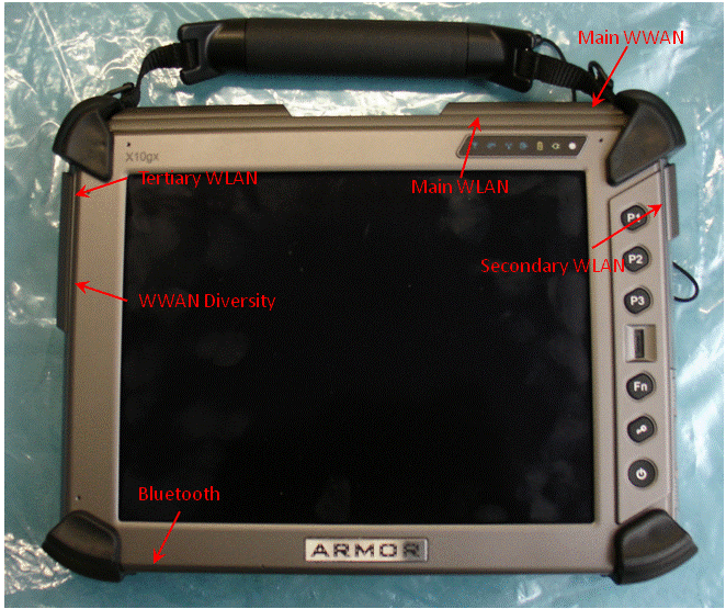
DRS Tactical Systems ARMOR X10gx Tablet PC External Photos Figure 1 Front View Figure 2 Back View Figure 3 Bottom View – Bluetooth Antenna Figure 4 Left View – WWAN Diversity/WLAN Tertiary Antennas Figure 5 Top View – WWAN Main/ WLAN Main Figure 6 Right View – WLAN Secondary

ID Label/Location Info

ARMOR X10gx Label & Location Size: 3”x2.375” SN and PN printed at time of manufacture

ID Label/Location Info

FCC ID: RK9-BTC04R IC ID:XXXX-XXXXXXCMII ID: XXXXXXXXXXApproval No.: ETA-xx/yyyy Model: BTC04R MADE IN XXXX 12 mm 12 mm CastleNet Technology Inc.

Internal Photos

Page 2 Page 3 Brand: WGT/ Model: L390x Page 4 Page 5 Brand: FVC/ Model: M570x Page 6 Page 7 Brand: FVC/ Model: M735x Page 8 Page 9 Brand: FVC/ Model: M860x Page 10 Page 11 Brand: FVC/ Model: M730x Page 12 Page 13 Brand: WGT/ Model: M740x Page 14 Page 15 Brand: WGT/ Model: M720x Page 16 Page 17 Brand: FVC/ Model: M760x Page 18 Page 19 Brand: FVC/ Model: TN120R Page 20 Page 21 Brand: SA/ Model: M770x Page 22 Page 23 Brand: FVC/ Model: M540x Page 24

Internal Photos

DRS Tactical Systems ARMOR X10gx Tablet PC Internal Photos Figure 1 Open Tablet Halves Figure 2 Figure 3 Main Board Figure 4 Power Board Figure 5 Flex Space Board with Radio Modules Installed Figure 6 Flex Space Board with Radios Removed Figure 7 Radio Modules

RF Exposure Info

© 2010 RF Exposure Lab, LLC This report shall not be reproduced except in full without the written approval of RF Exposure Lab, LLC. 802 N. Twin Oaks Valley Road, Suite 105 • San Marcos, CA 92069 • U.S.A. TEL (760) 737-3131 • FAX (760) 737-9131 http://www.rfexposurelab.com CERTIFICATE OF COMPLIANCE SAR EVALUATION DRS Tactical Systems Dates of Test: June 14 - 21, 2010 1110 W. Hibiscus Blvd. Test Report Number: SAR.20100604 Melbourne, FL 32901 Revision D This wireless mobile and/or portable device has been shown to be compliant for localized specific absorption rate (SAR) for uncontrolled environment/general exposure limits specified in ANSI/IEEE Std. C95.1-1999 and had been tested in accordance with the measurement procedures specified in IEEE 1528-2003, OET Bulletin 65 Supp. C, RSS-102 and Safety Code 6 (See test report). I attest to the accuracy of the data. All measurements were performed by myself or were made under my supervision and are correct to the best of my knowledge and belief. I assume full responsibility for the completeness of these measurements and vouch for the qualifications of all persons taking them. RF Exposure Lab, LLC certifies that no party to this application has been denied FCC benefits pursuant to Section 5301 of the Anti-Drug Abuse Act of 1988, 21 U.S.C. 853(a). Jay M. Moulton Vice President Certificate # 2387.01 FCC ID: UGLX10GX IC Certificate: 7888B-X10GX Model(s): X10gx WWAN Module: Sierra Wireless Gobi2000 FCC IC: N7NGOBI2 IC: 2417C-GOBI2 WLAN Module: Intel WiFi Link 5300 FCC ID: PD9533ANH IC: 1000M-533ANH BT Module: Castle Tech. BTC04R200B FCC ID: RK9-BTC04R IC: 4729A-BTC04R Test Sample: Engineering Unit same as Production Serial No.: 814GM01006G01200011M000 Equipment Type: Wireless Tablet PC Classification: Portable Transmitter Next to Body TX Frequency Range: 824.2–848.8 MHz, 1850.2–1909.8 MHz, 2402–2480 MHz, 2412–2462 MHz, 5180 – 5240 MHz, 5260 – 5320 MHz, 5500 – 5700 MHz, 5745 – 5825 MHz Frequency Tolerance: ± 25 ppm Maximum RF Output: 850 MHz (GSM) – 32.88 dBm, 850 MHz (CDMA) – 24.66 dBm, 850 MHz (WCDMA) – 24.23 dBm, 1900 MHz (GSM) – 29.46 dBm, 1900 MHz (CDMA) – 24.65 dBm, 1900 MHz (WCDMA) – 24.13 dBm, 2450 Mhz (b) – 19.73 dBm, 2450 MHz (g) – 23.88 dBm, 5200 MHz – 16.68 dBm, 5600 MHz – 16.72 dBm, 5800 MHz – 24.72 dBm Conducted Signal Modulation: GMSK, 8-PSK, CDMA, WCDMA, OFDM, DSSS Antenna Type (Length): Internal (Yageo WWAN/WLAN Main P/N CAN43139GWWI01201, WWAN/WLAN Aux P/N CAN43139GWWI01202, WLAN MIMO CAN43139GWWI01203 Battery: Std. (DRS Tactical P/N 0300-15663-2400) Battery Pack Application Type: Certification FCC Rule Parts: Part 22, 24, Sec. 15.247, Sec 15.407 Industry Canada: RSS-102, Safety Code 6 FCC ID: UGLX10GX © 2010 RF Exposure Lab, LLC Page 2 of 300 This report shall not be reproduced except in full without the written approval of RF Exposure Lab, LLC. Table of Contents 1. Introduction ........................................................................................................................................... 3 SAR Definition [5] ..................................................................................................................................... 3 2. SAR Measurement Setup ..................................................................................................................... 4 Robotic System ......................................................................................................................................... 4 System Hardware ..................................................................................................................................... 4 System Description ................................................................................................................................... 4 E-Field Probe ALS-E-020 ......................................................................................................................... 5 3. Robot Specifications ............................................................................................................................. 7 4. Probe and Dipole Calibration ............................................................................................................... 8 5. Phantom & Simulating Ti ssue Specifications ....................................................................................... 9 SAM Phantom ........................................................................................................................................... 9 Brain & Muscle Simulating Mixture Characterization ................................................................................ 9 Device Holder ........................................................................................................................................... 9 6. Definition of Referenc e Points ............................................................................................................ 10 Ear Reference Point ............................................................................................................................... 10 Device Reference Points ........................................................................................................................ 10 7. Test Configuration Pos itions .............................................................................................................. 11 Positioning for Cheek/Touch [5] .............................................................................................................. 11 Positioning for Ear / 15 ̊ Tilt [5] ............................................................................................................... 12 Body Worn Configurations ...................................................................................................................... 13 8. ANSI/IEEE C95.1 – 1999 RF Exposure Limits [2] .............................................................................. 14 Uncontrolled Env…

Text truncated - open the document above for the full version.

RF Exposure Info

FCC ID: UGLX10GX © 2010 RF Exposure Lab, LLC Page 196 of 300 This report shall not be reproduced except in full without the written approval of RF Exposure Lab, LLC. Appendix D – Probe Calibration Data Sheets NCL CALIBRATION LABORATORIES Calibration File No.: CP-1079 Client.: RFEL C E R T I F I C A T E OF C A L I B R A T I O N It is certified that the equipment identified below has been calibrated in the NCL CALIBRATION LABORATORIES by qualified personnel following recognized procedures and using transfer standards traceable to NRC/NIST. Equipment: Miniature Isotropic RF Probe 835 MHz BODY Calibration Manufacturer: APREL Laboratories Model No.: E-020 Serial No.: 217 Calibration Procedure: SSI/DRB-TP-D01-032-E020-V2 Project No: RFEL-E020-CAL-5477 Calibrated: 21 st October 2009 Released on: 28 th October 2009 NCL CALIBRATION LABORATORIES 51 SPECTRUM WAY Division of APREL Lab. NEPEAN, ONTARIO TEL: (613) 820-4988 CANADA K2R 1E6 FAX: (613) 820-4161 NCL Calibration Laboratories Division of APREL Laboratories. Page 2 of 10 This page has been reviewed for content and attested to on Page 2 of this document. Introduction This Calibration Report reproduces the results of the calibration performed in line with the SSI/DRB-TP-D01-032-E020-V2 E-Field Probe Calibration Procedure. The results contained within this report are for APREL E-Field Probe E-020 217. References SSI/DRB-TP-D01-032-E020-V2 E-Field Probe Calibration Procedure IEEE 1528 “Recommended Practice for Determining the Peak Spatial-Average Specific Absorption Rate (SAR) in the Human Body Due to Wireless Communications Devices: Experimental Techniques” SSI-TP-011 Tissue Calibration Procedure IEC 62209 “Human exposure to radio frequency fields from hand-held and body- mounted wireless communication devices – Human models, instrumentation, and procedures –Part 1 & 2: Procedure to determine the Specific Absorption Rate (SAR) for hand-held devices used in close proximity of the ear (frequency range of 300 MHz to 3 GHz)” IEEE 1309 Draft Standard for Calibration of Electromagnetic Field Sensors and Probes, Excluding Antennas, from 9kHz to 40GHz Conditions Probe 217 was a re-calibration. Ambient Temperature of the Laboratory: 22 °C +/- 0.5°C Temperature of the Tissue: 21 °C +/- 0.5°C NCL Calibration Laboratories Division of APREL Laboratories. Page 3 of 10 This page has been reviewed for content and attested to on Page 2 of this document. Calibration Results Summary Probe Type: E-Field Probe E-020 Serial Number: 217 Frequency: 835 MHz Sensor Offset: 1.56 mm Sensor Length: 2.5 mm Tip Enclosure: Ertalyte* Tip Diameter: <5 mm Tip Length: 60 mm Total Length: 290 mm *Resistive to recommended tissue recipes per IEEE-1528 Sensitivity in Air Channel X: 1.2 μV/(V/m) 2 Channel Y: 1.2 μV/(V/m) 2 Channel Z: 1.2 μV/(V/m) 2 Diode Compression Point: 95 mV NCL Calibration Laboratories Division of APREL Laboratories. Page 4 of 10 This page has been reviewed for content and attested to on Page 2 of this document. Sensitivity in Body Tissue Measured Frequency: 835 MHz Epsilon: 54.9 (+/-5%) Sigma: 1.04 S/m (+/-5%) ConvF Channel X: 6.1 Channel Y: 6.1 Channel Z: 6.1 Tissue sensitivity values were calculated using the load impedance of the APREL Laboratories Daq-Paq. Boundary Effect: Uncertainty resulting from the boundary effect is less than 2% for the distance between the tip of the probe and the tissue boundary, when less than 2.44mm. Spatial Resolution: The measured probe tip diameter is 5 mm (+/- 0.01 mm) and therefore meets the requirements of SSI/DRB-TP-D01-032 for spatial resolution. NCL Calibration Laboratories Division of APREL Laboratories. Page 5 of 10 This page has been reviewed for content and attested to on Page 2 of this document. Receiving Pattern 835 MHz (Air) Receiving Pattern Probe s/n 217 835MHz 0 0.2 0.4 0.6 0.8 1 1.2 0 10 20 30 40 50 60 70 80 90 100 110 120 130 140 150 160 170 180 190 200 210 220 230 240 250 260 270 280 290 300 310 320 330 340 350 Ch1Ch2Ch3Tot NCL Calibration Laboratories Division of APREL Laboratories. Page 6 of 10 This page has been reviewed for content and attested to on Page 2 of this document. Isotropy Error 835 MHz (Air) Isotropy Error Probe s/n 217 835MHz -10 -9 -8 -7 -6 -5 -4 -3 -2 -1 0 1 2 3 4 5 6 7 8 9 10 0100200300 Error [dB] Isotropy Plot Probe s/n 217 835MHz 0 0.1 0.2 0.3 0.4 0.5 0.6 0.7 0.8 0100200300 Degrees (x10) Voltage (mV) Ch1Ch2Ch3 Isotropicity Tissue: 0.10 dB NCL Calibration Laboratories Division of APREL Laboratories. Page 7 of 10 This page has been reviewed for content and attested to on Page 2 of this document. Dynamic Range Probe 217 Dynamic Range 0.01 0.1 1 10 100 1000 10000 1.0010.00100.001,000.0010,000.00100,000.001,000,000.0010,000,000.00 Electric Field [(V/m)^2] Voltage [microV…

Text truncated - open the document above for the full version.

Contact Information

Applicant

Albert Fernandez(Test Engineer)
[email protected]321-727-3672Fax: 321-676-6189

Technical Contact

DRS Tactical Systems, Inc.David Ball
[email protected]321 727 3672

1100 West Hibiscus Blvd. · Melbourne, Florida · United States

Non-Technical Contact

DRS Tactical Systems, Inc.David Ball
[email protected]321 727 3672

Test Firm

Bureau Veritas CPS (H.K.) Ltd. Taoyuan BranchTommy Wu
[email protected]886-2-2605-2180-3Fax: 886-2-2605-2943

Technical Specifications

#Rule PartsFrequency RangePower Output
115C2.40 GHz - 2.48 GHz3.00 mW
Confidentiality
Long Term
Grant Notes
Power Output listed is conducted. The antenna(s) used for this transmitter must not be co-located or operating in conjunction with any other antenna or transmitter except as described in this filing. End-users must be provided with transmitter operating conditions for satisfying RF exposure compliance. The highest reported Body SAR values: 1.169 W/kg.

Other Applications from DRS Tactical Systems, Inc.
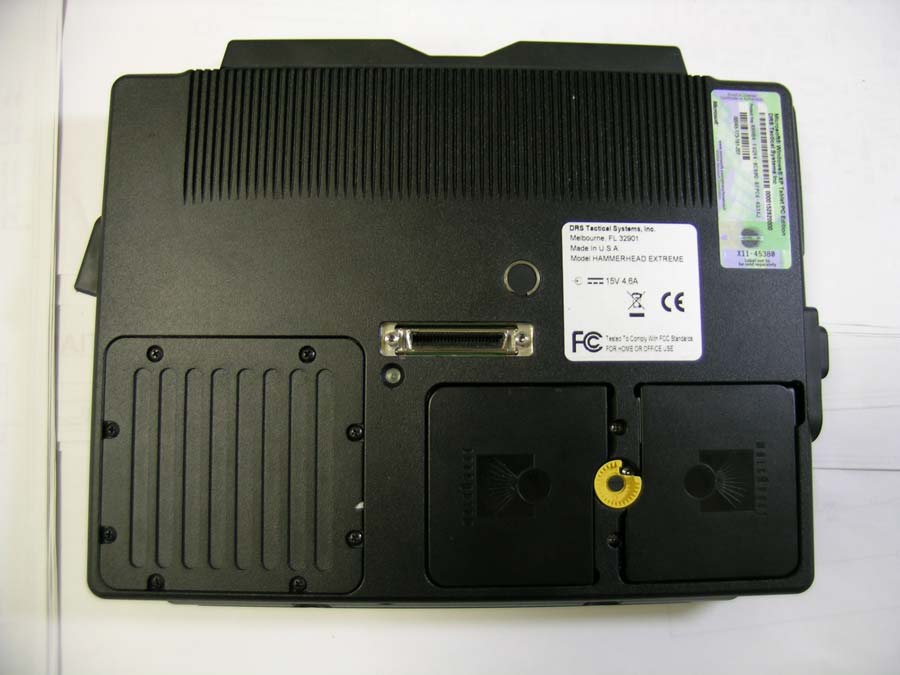
TABLET PC - FCC ID UGL9800178540001 - DRS Tactical Systems, Inc.
UGL9800178540001

TABLET PC

Dec 14, 2006

Equipment Class

DSS - Part 15 Spread Spectrum Transmitter