UGP-WSW001Wireless 1 Channel Low Voltage Switch
BTX Holdings Inc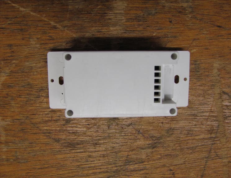
Click to zoom
Application Details
- Equipment Class
- DSR - Part 15 Remote Control/Security Device Transceiver
- Date of Grant
- Jun 29, 2010
- Application Purpose
- Original Equipment
- Date of Application
- Jun 28, 2010
- Equipment Note
- Wireless 1 Channel Low Voltage Switch
- Frequency Range
- 433.92000000 - 433.92000000
- Company
- BTX Holdings Inc
- Country
- United States
Documents & Files
Document Text
Text extracted from the exhibit documents filed with the FCC. Open a document above to read the original.
Users Manual
Operation Instructions for MMC Control System MMC Control Instructions to the User for FCC This equipment has been tested and found to comply with the limits for a class B digital device pursuant to part 15 of the FCC Rules. These limits are designed to provide reasonable protection against harmful interference in a residential installation. This equipment generates, uses and can radiate radio frequency energy and if not installed and used in accordance with the instructions, may cause harmful interference to radio communications. However, there is no guarantee that interference will not occur in a particu- lar installation. If this equipment does cause harmful interference to radio or television reception, which can be determined by turning the equipment off and on, the user is encouraged to try to correct the interference by one or more of the following measures: • Reorient or relocate the receiving antenna. • Increase the separation between the equipment and receiver. • Connect the equipment into an outlet on a circuit different from that to which the receiver is connected. • Consult the dealer or an experienced radio/TV technician for help. Operation with non-approved equipment or unshielded cables is likely to result in interference to radio and TV reception. The user is cautioned that changes and modifications made to the equipment without the approval of the manufacturer could void the user’s authority to operate the equipment. This device complies with Part 15 of the FCC Rules. Operation is subject to the following two conditions: (1) This device may not cause harmful interference and (2) this device must accept any interference received, including interference that may cause undesired operation. Information for Canadian Users (IC Notice) Operation is subject to the following two conditions: (1) This device may not cause interference, and (2) this device must accept any interference, including interference that may cause undesired operation of the device. Dip Switch Table for MMC RF Board 111Maintained on123Open is Open and Close is Close If switch 3 is off, the action is ‘open is open and close is close’. If switch 3 is on, the action is ‘open is close and close is open’. 11Momentary to 1Maintained on123Open is Open and Close is Close 11Momentary 1 on123Open is Open and Close is Close 11Maintained 1 on123Open is Close and Close is Open 1Momentary to 11Maintained on123Open is Close and Close is Open 1Momentary 11 on123Open is Close and Close is Open Basic Wiring of MMC-RF Board Functional Explanation for Dip Switch Switch Pin Out for MMC MMC Programming 1) Programming the Handsender for One Motor Note: To put MMC into program mode, unplug the MMC for 30 seconds and then reconnect. The program mode is now engaged for the first three minutes the MMC has been plugged in. When pro- gramming a new system, any Tumo systems within range that have been programmed within the last three minutes must be unplugged to prevent them from becoming reconfigured to match the new system. Each MMC can learn up to four channels. To delete all channels from a programmed motor, make sure the MMC is in program mode and press the STOP and DOWN buttons simultaneously . The MMC handsender can control up to 6 MMC’s or 6 groups of MMC’s. Before using the handsender, the MMC needs to recognize the handsender. Put MMC into program mode and press the channel selection button. This will light up the last channel that was selected. Press again and the next channel will be selected and light up, etc. Continue pressing the channel selection button until the channel you wish to program is selected and the corresponding channel number LED lights up, then press the stop button. Before the MMC leaves program mode, press and hold the UP and DOWN buttons simultaneously. The selected channel number will light up with a slow flash. The MMC will then react with a movement to indicate that the re- ceiver is receiving the signal from the handsender and to confirm that communication between MMC and handsender is established. Press the LEFT or RIGHT button to test. The channel has now been programmed. 2) Programming one Handsender to Control Multiple Receivers or Multiple Groups of Receivers. Note: When programming a new system, any Tumo systems within range that have been programmed within the last three minutes must be unplugged to prevent them from becoming reconfigured to match the new system. Select channel on the handsender (for example, channel 2) by repeatedly pressing the channel selection button until the "2" is lit. To program another MMC to recognize this same channel(2) repeat the same programming procedure in step 1 for the new MMC. Six MMC’s can be programmed to be controlled by the same handsender this way. Select this channel to confirm that a particular receiver has been pro- grammed to communicate with this channel by pressing LEFT or RIGHT. You should see the system react. Continue this procedure until all six channel number LEDs light up. All the MMC’s will now respond when you press the LEFT or RIGHT button. Any one of the six channels can be programmed this way for a group of receivers. In this case, each channel will control all the receivers in that group at the same time. Right Up Channel Indicator Stop Left Down Channel Selection Button MMC Programming 3) Delete Channel Settings at the MMC Using the CHANNEL SELECTION button, select the channel programmed to the MMC for which you wish to cancel the channel setting. Press and hold the UP and STOP buttons until the receiver reacts with 4 clicks. This channel setting has now been deleted from the MMC. If you now press or hold any of the directional buttons for that channel, the MMC should not click. 4) Replacing the Handsender Battery The handsender is powered by two lithium-ion button batteries, model number: CR24300. This battery style is fairly common and should be easy to find at most retail stores that sell electronic equipment or accessories. The ba…
Text truncated - open the document above for the full version.
Attestation Statements
.. utomatlng the • World's WlndowsTM ~ . www.a-w:JClnc.com • Window Automalion • Motorization Supply • Export Division • Corporate Offices 10763 Sonden Drive Dollas, lX 75238·1336 (214) 340·2800 (800) 422-8839 FAX (214) 343-2252 www.btxinuom btxwindow@btxinc(om January 25,2010 CETCB 114 Olinda Drive Brea, CA 92823 Gentlemen: This is a letter of authorization to accept Compatible Electronics, Inc., specifically including the employees of Compatible Electronics, as an Agent for BTX Holdings, Inc., for a period of one year, to sign applications before the Commission on our behalf, to make representations to you on our behalf, and to receive arid exchange data between our company and the Cotnm:ission in connection with certification of the following BTX product: Transmitters and Receiver under FCC Docket Number 20780 and General Docket Number 80-284 pursuant to Part 15 of FCC Rules and Regulations. Please also accept this letter as an attestation that neither BTX nor any of its officers, directors, or persons holding 5% or more of the ou,tstanding stock or shares, voting or non-voting, have been denied federal benefits under section 5301 of the Anti-Drug-Abuse act of 1988,21 US.c. 853(a). In addition, BTX will notify the Federal Communications Commission if, at any time, the situation changes causing BTX to be denied federal benefits. If you have any further questions or need additional information, please feel free to give me a call at 214-340-2800. Sincerely, 7-7~ 7--= Kevin Keenan Business Development Manager
Attestation Statements
- utomating the ~ W. orld's WindowsTM www.B..-:x:lnc.com • Window Automation • Motorization Supply • Export Division • Corporate Offices 10763 Sanden Drive Dallas, TX 75238-1336 (214) 340-2800 (800) 422-8839 FAX (214) 343-2252 www.btxinc.com [email protected] • April 6, 2010 Compatible Electronics TCB 114 Olinda Drive Brea, California 92823 Subject: TCB application submittal Gentlemen: We, BTX Holdings Inc., would like to declare that the application being submitted forthe device with FCC ID: UGP-WSW001, has not been submitted to another TCB or FCC for certification. If you have any questions, please do not hesitate to contact us at (214-340 2800). Sincerely, /-~~ Kevin Keenan Business Development Manager
Cover Letter(s)
utomating the World's ,Windows"' ~ www.BTXI"c.coon • Window Automation • Motorization Supply • Export Division • Corporate Offices 10763 Sanden Drive Dallas, TX 75238-1336 (214) 340·2800 (800) 422-8839 FAX (214) 343-2252 www.blxinuom [email protected] • January 25, 2010 Compatible Electronics TCB 114 Olinda Drive Brea, California 92823 Subject: Request for withholding from public disclosure the schematics, block diagrams, and operational description pursuant to an application for certification Gentlemen: We, BTX Holdings Inc., would like to request that all schematics, block diagrams, and operational descriptions submitted with the application for certification be withheld from public disclosure as per Section 0.459 ofFCC Rules. . This request is made under the provisions of Section 0.457 (d) ofthe Commission's Rules, and Section 552 (b)(4) of the Freedom ofInformation Act. These sections authorize the withholding from public inspection, those materials which would be privileged as a matter of law if retained by the person submitting them, and materials which would not customarily be released to the public by that person. Ifyou have any questions, please do not hesitate to contact us at 214-340-2800. Sincerely, ~K'~ Kevin Keenan Business Development Manager
Cover Letter(s)
1 Scott McCutchan From: Scott McCutchan [[email protected]] Sent: Thursday, May 27, 2010 7:18 PM To: '[email protected]' Cc: '[email protected]'; '[email protected]' Subject: FCC ID: UGP-WSW001 Mr. Fujimoto: In order for processing of this certification application (FCC ID: UGP-WSW001) to continue, the following issue(s) will have to be addressed: 1) The two-condition statement contained in section 15.31(a)(3) of the FCC rules does not appear on the device label. Per section 15.31(a)(5), when the device is so small that it is not practicable to put this statement on the device, it can alternatively be placed in the instruction manual. Please submit either a revised label, or a revised user’s manual, with the statement included. 2) The schematic diagrams submitted are incomplete. Please submit the full set of schematics 3) The FCC ID printed on the example label is “UGP-W5W001”, which does not match the FCC ID on the rest of the application. Please correct the label, or if the label is correct, please submit the application with the correct identifier. 4) Based on the submitted duty cycle plots, the on-time used for the duty cycle calculation is incorrect. Please correct. The item(s) indicated above must be submitted before processing can continue on the above referenced application. Failure to provide the requested information within 60 days of the original e-mail date may result in application dismissal and forfeiture of the filing fee. Also, please note that partial responses increase processing time and should not be submitted. Please upload responses and/or exhibits to the electronic filing website. Your correspondence number is FCC ID: UGP-WSW001-1. Best regards, Scott McCutchan Operations Manager Compatible Electronics TCB
Cover Letter(s)
Correspondence by Project Project Number: 1977480606 Correspondence Number Memo UGP-WSW001-1 1) The two-condition statement contained in section 15.31(a)(3) of the FCC rules does not appear on the device label. Per section 15.31(a)(5), when the device is so small that it is not practicable to put this statement on the device, it can alternatively be placed in the instruction manual. Please submit either a revised label, or a revised user’s manual, with the statement included. Response: A photo has been taken to show the unit is smaller than a person's hand and also the owner's manual has been revised to include the FCC statement. 2) The schematic diagrams submitted are incomplete. Please submit the full set of schematics Response: The Schematics have been revised. 3) The FCC ID printed on the example label is “UGP-W5W001”, which does not match the FCC ID on the rest of the application. Please correct the label, or if the label is correct, please submit the application with the correct identifier. Response: The FCC ID has been revised to show the correct FCC ID. 4) Based on the submitted duty cycle plots, the on-time used for the duty cycle calculation is incorrect. Please correct. Response: The duty cycle information has been revised to show the correct calculation.
Test Report
Report Number: B91229D1 FCC Part 15 Subpart B and FCC Section 15.231 Test Report Wireless 1 Channel Low Voltage Switch Model: WSW001 Brea Division 114 Olinda Drive Brea, CA 92823 (714) 579-0500 Agoura Division 2337 Troutdale Drive Agoura, CA 91301 (818) 597-0600 Silverado Division 19121 El Toro Road Silverado, CA 92676 (949) 589-0700 Lake Forest Division 20621 Pascal Way Lake Forest, CA 92630 (949) 587-0400 Page 1 of 17 FCC PART 15 SUBPART B and C TEST REPORT for WIRELESS 1 CHANNEL LOW VOLTAGE SWITCH Model: WSW001 Prepared for BTX, INC. 10763 SANDEN DRIVE DALLAS, TEXAS 75238-1336 Prepared by:_____________________ KYLE FUJIMOTO Approved by:____________________ JAMES ROSS COMPATIBLE ELECTRONICS INC. 114 OLINDA DRIVE BREA, CALIFORNIA 92823 (714) 579-0500 DATE: FEBRUARY 17, 2010 REPORT APPENDICES TOTAL BODY A B C D E PAGES 17 2 2 2 11 10 44 This report shall not be reproduced except in full, without the written approval of Compatible Electronics. Report Number: B91229D1 FCC Part 15 Subpart B and FCC Section 15.231 Test Report Wireless 1 Channel Low Voltage Switch Model: WSW001 Brea Division 114 Olinda Drive Brea, CA 92823 (714) 579-0500 Agoura Division 2337 Troutdale Drive Agoura, CA 91301 (818) 597-0600 Silverado Division 19121 El Toro Road Silverado, CA 92676 (949) 589-0700 Lake Forest Division 20621 Pascal Way Lake Forest, CA 92630 (949) 587-0400 Page 2 of 17 TABLE OF CONTENTS Section / Title PAGE GENERAL REPORT SUMMARY 4 SUMMARY OF TEST RESULTS 4 1. PURPOSE 5 2. ADMINISTRATIVE DATA 6 2.1 Location of Testing 6 2.2 Traceability Statement 6 2.3 Cognizant Personnel 6 2.4 Date Test Sample was Received 6 2.5 Disposition of the Test Sample 6 2.6 Abbreviations and Acronyms 6 3. APPLICABLE DOCUMENTS 7 4. DESCRIPTION OF TEST CONFIGURATION 8 4.1 Description of Test Configuration – EMI 8 4.1.1 Cable Construction and Termination 9 5. LISTS OF EUT, ACCESSORIES AND TEST EQUIPMENT 10 5.1 EUT and Accessory List 10 5.2 EMI Test Equipment 11 6. TEST SITE DESCRIPTION 12 6.1 Test Facility Description 12 6.2 EUT Mounting, Bonding and Grounding 12 6.3 Facility Environmental Characteristics 12 7. TEST PROCEDURES 13 7.1 RF Emissions 13 7.1.1 Conducted Emissions Test 13 7.1.2 Radiated Emissions (Spurious and Harmonics) Test 14 7.2 Bandwidth of the Fundamental 16 8. CONCLUSIONS 17 Report Number: B91229D1 FCC Part 15 Subpart B and FCC Section 15.231 Test Report Wireless 1 Channel Low Voltage Switch Model: WSW001 Brea Division 114 Olinda Drive Brea, CA 92823 (714) 579-0500 Agoura Division 2337 Troutdale Drive Agoura, CA 91301 (818) 597-0600 Silverado Division 19121 El Toro Road Silverado, CA 92676 (949) 589-0700 Lake Forest Division 20621 Pascal Way Lake Forest, CA 92630 (949) 587-0400 Page 3 of 17 LIST OF APPENDICES APPENDIX TITLE A Laboratory Recognitions B Modifications to the EUT C Additional Models Covered Under This Report D Diagram, Charts, and Photos • Test Setup Diagram • Antenna and Amplifier Factors • Radiated Emissions Photos E Data Sheets LIST OF FIGURES FIGURE TITLE 1 Conducted Emissions Test Setup 2 Plot Map And Layout of Radiated Test Site – 3 Meters Report Number: B91229D1 FCC Part 15 Subpart B and FCC Section 15.231 Test Report Wireless 1 Channel Low Voltage Switch Model: WSW001 Brea Division 114 Olinda Drive Brea, CA 92823 (714) 579-0500 Agoura Division 2337 Troutdale Drive Agoura, CA 91301 (818) 597-0600 Silverado Division 19121 El Toro Road Silverado, CA 92676 (949) 589-0700 Lake Forest Division 20621 Pascal Way Lake Forest, CA 92630 (949) 587-0400 Page 4 of 17 GENERAL REPORT SUMMARY Compatible Electronics Inc. generates this electromagnetic emission test report, which is an independent testing and consulting firm. The test report is based on testing performed by Compatible Electronics personnel according to the measurement procedures described in the test specifications given below and in the "Test Procedures" section of this report. The measurement data and conclusions appearing herein relate only to the sample tested and this report may not be reproduced without the written permission of Compatible Electronics, unless done so in full. This report must not be used to claim product endorsement by NVLAP, NIST or any other agency of the U.S. Government. Device Tested: Wireless 1 Channel Low Voltage Switch Model: WSW001 S/N: N/A Product Description: See Expository Statement Modifications: The EUT was not modified in order to meet the specifications. Customer: BTX, Inc. 10763 Sanden Drive Dallas, Texas 75238-1336 Test Date(s): December 28 and 29, 2009 Test Specifications: EMI requirements CFR Title 47, Part 15, Subpart B Test Procedure: ANSI C63.4 Test Deviations: The test procedure was not deviated from during the testing. SUMMARY OF TEST RESULTS TEST DESCRIPTION RESULTS 1 Conducted RF Emissions, 150 kHz – 30 MHz The EUT does not directly or indirectly connect to the AC mains, thus this test was not performed. 2 Radiated RF Emissions 10 kHz – 4400 MHz (Transmitter Portion) Complies with the limits of CFR Title 47, Part 15, Subpart C, sections 15.205, 15.209, and 15.231. Highest reading in relation to spec limit: 72.67 (Avg) dBuV @ 433.92 MHz (*U = 4.22 dB) 3 Radiated RF Emissions 10 kHz – 4400 MHz (Digital Portion) Complies with the Class B limits of CFR Title 47, Part 15, Subpart B. Highest reading in relation to spec limit: 28.54 dBuV @ 41.358 MHz (*U = 4.03 dB) *U = Expanded Uncertainty with a coverage factor of k=2 Report Number: B91229D1 FCC Part 15 Subpart B and FCC Section 15.231 Test Report Wireless 1 Channel Low Voltage Switch Model: WSW001 Brea Division 114 Olinda Drive Brea, CA 92823 (714) 579-0500 Agoura Division 2337 Troutdale Drive Agoura, CA 91301 (818) 597-0600 Silverado Division 19121 El Toro Road Silverado, CA 92676 (949) 589-0700 Lake Forest Division 20621 Pascal Way Lake Forest, CA 92630 (949) 587-0400 Page 5 of 17 1. PURPOSE This document is a qualification test report based on the Electromagnetic Interference (EMI) tests performed on the Wireless 1 Channel Low Voltage Switch,…
Text truncated - open the document above for the full version.
Contact Information
Applicant
Ben Woodall(GM)
Technical Contact
Compatible Electronics, Inc.Kyle Fujimoto
[email protected]714-579-0500
114 Olinda Drive · Brea, California · United States
Test Firm
Compatible Electronics, Inc.Michael Christensen
Technical Specifications
| # | Rule Parts | Frequency Range | Power Output |
|---|---|---|---|
| 1 | 15.231 | 433.92 MHz - 433.92 MHz | - |
Other Applications from BTX Holdings Inc
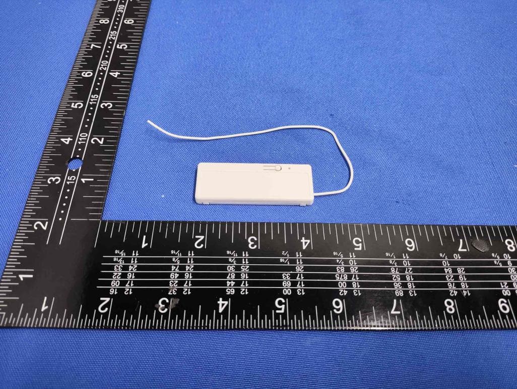
UGP-4049270
Dec 17, 2025BTX Smart Link Pro
Equipment Class
DTS - Digital Transmission System
UGP-SMTCH001
Jun 29, 2010Smart Touch Transmitter
Equipment Class
DSC - Part 15 Security/Remote Control Transmitter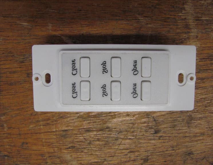
UGP-WSW002
Jun 28, 2010Wireless 2 Channel Low Voltage Switch
Equipment Class
DSC - Part 15 Security/Remote Control Transmitter