FCCID.CO- FCC ID Database
HomeCompaniesEquipment ClassesSearch

© 2026 FCC ID Database. All rights reserved.

AboutContactData sourced from FCC public records
  1. Home/
  2. H-ITT, LLC/
  3. UH9RX4000

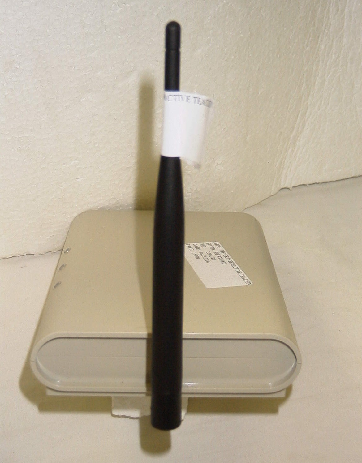
UH9RX4000RF BASE

H-ITT, LLC
RF BASE - FCC ID UH9RX4000 - H-ITT, LLC
Click to zoom

Application Details

Equipment Class
DXX - Part 15 Low Power Communication Device Transmitter
Date of Grant
Nov 02, 2006
Application Purpose
Original Equipment
Date of Application
Nov 02, 2006
Equipment Note
RF BASE
Frequency Range
2401.00000000 - 2462.30000000
Company
H-ITT, LLC
Country
United States

Documents & Files

Select a file to view

Users Manual

↗

Cover Letter(s)

↗
↗

External Photos

↗

ID Label/Location Info

↗
↗

Internal Photos

↗

Test Report

↗

Test Setup Photos

↗
↗

Document Text

Text extracted from the exhibit documents filed with the FCC. Open a document above to read the original.

Users Manual

Figure 1 H-ITT RFbase H-ITT RFbase, model number 4000 instruction manual GENERAL: The RFbase communicates with all H-ITT RF clickers. The H-ITT acquisition program, version 1.9.1 or higher must be installed on your PC. There is no limit to the number of RF clickers (or RF links) that can be used with a single RFbase. The RFbase has 62 RF channels that can be selected, and has 4 selectable baud rates. The 62 RF channels are provided so that a classroom can have its unique RF channel so as not to interfere with adjacent classrooms, or other fixed frequency devices already installed in the classroom. INITIAL SET-UP: The unit provides both USB and Serial communications ports. Connect either of these ports to your classroom PC (do not connect both). The USB connection provides power to the unit, so this is the only connection needed. If the serial port is used, the unit must have an external power supply connected, use H-ITT part number #2003. On power up, the YELLOW indicator light will turn on and both the PC com and RF com indicators will blink 4 times. If the RF com indicator blinks more at a faster rate than the 4 initial blinks, this can indicate that the RF channel selected may have another fixed frequency transmitter operating on the same channel within the range of the base. If this occurs, it is recommended that a different channel be selected. Additionally, the RF channel should be selected based on a cooperative effort with nearby classrooms so that each classroom within about 500 feet operates the H-ITT CRS on a unique RF channel selection. CHANGING THE RF CHANNEL: The RFbase snap on cover must be removed to access the RF channel selector switch. To remove the cover, squeeze the bottom sides near the ends, and lift the top cover, it will un-snap. With the cover removed, Figure 1 shows the internal location of the 10- position DIP switch used for set up. Switch positions 1 through 6 set the RF channel. Table 1 shows the numeric value of the 62 selectable channels. In general, the 6 switches represent a 6 bit binary number. To decode this binary number, switch 1 is the LSB and switch 6 is the MSB. When the switch is ON the binary value is zero, and when the switch is OFF the binary value is one. The switch setting of 00 (all on) and 11 (all off) should not be used. In order for the student’s clickers to operate on the same RF channel as the RFbase, the selected RF channel must be published, or otherwise be made known to the students in the classroom where the H-ITT CRS is being used. A description of Student “log-in” for the classroom RF channel is provided in the clickers users guide and also in appendix A herein. 1 2 3 4 5 6 7 8 9 10 Switch positions 1 through 6 select the RF channel. Switch 7 is reserved Switch positions 8 and 9 select the baud rate Switch 10 sets the operating mode Circuit board, reference location for the10 position DIP switch ANTENNA Switch settings shown are the factory default: 1. RF channel is 07 2. Baud rate is 19.2K 3. Clicker mode USB Port Serial Port DC power jack Power indicator Antenna PC com indicator RF com indicator TABLE 1, SWITCH SETTINGS and resulting CHANNEL NUMBER SWITCH SETTING SWITCH SETTING Channel #6 #5 #4 #3 #2 #1 Channel #6 #5 #4 #3 #2 #1 01 ON ON ON ON ON OFF 33 OFF ON ON ON ON OFF 02 ON ON ON ON OFF ON 34 OFF ON ON ON OFF ON 03 ON ON ON ON OFF OFF 35 OFF ON ON ON OFF OFF 04 ON ON ON OFF ON ON 36 OFF ON ON OFF ON ON 05 ON ON ON OFF ON OFF 37 OFF ON ON OFF ON OFF 06 ON ON ON OFF OFF ON 38 OFF ON ON OFF OFF ON 07 ON ON ON OFF OFF OFF 39 OFF ON ON OFF OFF OFF 08 ON ON OFF ON ON ON 40 OFF ON OFF ON ON ON 09 ON ON OFF ON ON OFF 41 OFF ON OFF ON ON OFF 10 ON ON OFF ON OFF ON 42 OFF ON OFF ON OFF ON 11 ON ON OFF ON OFF OFF 43 OFF ON OFF ON OFF OFF 12 ON ON OFF OFF ON ON 44 OFF ON OFF OFF ON ON 13 ON ON OFF OFF ON OFF 45 OFF ON OFF OFF ON OFF 14 ON ON OFF OFF OFF ON 46 OFF ON OFF OFF OFF ON 15 ON ON OFF OFF OFF OFF 47 OFF ON OFF OFF OFF OFF 16 ON OFF ON ON ON ON 48 OFF OFF ON ON ON ON 17 ON OFF ON ON ON OFF 49 OFF OFF ON ON ON OFF 18 ON OFF ON ON OFF ON 50 OFF OFF ON ON OFF ON 19 ON OFF ON ON OFF OFF 51 OFF OFF ON ON OFF OFF 20 ON OFF ON OFF ON ON 52 OFF OFF ON OFF ON ON 21 ON OFF ON OFF ON OFF 53 OFF OFF ON OFF ON OFF 22 ON OFF ON OFF OFF ON 54 OFF OFF ON OFF OFF ON 23 ON OFF ON OFF OFF OFF 55 OFF OFF ON OFF OFF OFF 24 ON OFF OFF ON ON ON 56 OFF OFF OFF ON ON ON 25 ON OFF OFF ON ON OFF 57 OFF OFF OFF ON ON OFF 26 ON OFF OFF ON OFF ON 58 OFF OFF OFF ON OFF ON 27 ON OFF OFF ON OFF OFF 59 OFF OFF OFF ON OFF OFF 28 ON OFF OFF OFF ON ON 60 OFF OFF OFF OFF ON ON 29 ON OFF OFF OFF ON OFF 61 OFF OFF OFF OFF ON OFF 30 ON OFF OFF OFF OFF ON 62 OFF OFF OFF OFF OFF ON 31 ON OFF OFF OFF OFF OFF 32 OFF ON ON ON ON ON SETTING THE BAUD RATE: The DIP switch positions 8 and 9 are used to set the baud rate of the RFbase. Reference figure 1 to locate the DIP switch, and table 2 for setting the desired baud rate. Table 2, SWITCH SETTINGS and resulting BAUD RATES. DIP SWITCH BAUD RATE 9 8 19.2K ON ON 38.4K ON OFF 57.6K OFF ON 115.2K OFF OFF OPERATING MODE: The RFbase has 2 operating modes: 1. Operating with H-ITT RF clickers. 2. Not used currently. DIP switch position10 is used to select the desired mode: ON is the RF clicker mode. The RFbase is factory set for operation with the H-ITT RF clickers. All above instructions apply when used for a H-ITT full RF based CRS. MOUNTING THE RFBASE. Before mounting the unit, connect the antenna to the screw on SMA connector on the end of the unit. The unit can be simply set on a table top, or mounted to a wall using the “key-hole” on the back of the unit to hang it. Position the antenna based on how the units is going to be mounted. Tests show the range is better when the unit is wall mounted with the antenna pointing up. For best performance: 1. The antenna should be vertical, or pointing up. 2. Avoid setting the unit on a metal table. 3. Mount the unit so it has a clear line-of-sight to the seats in the classroom. APPENDIX …

Text truncated - open the document above for the full version.

Cover Letter(s)

849 NW State Road 45 • P. O. Box 370 • Newberry, Florida 32669 USA Telephone (352) 472-5500 • (888) 472-2424 • FAX (352) 472-2030 • email: [email protected] TIMCO ENGINEERING INC. TCB & FCB 849 NW State Road 45 FCC Approvals Newberry, Florida 32669 Industry Canada Approvals http://www.timcoengr.com Notified Body for Europe 888.472.2424 352 472 5500 Fax. 352.472.2030 email: [email protected] November 10, 2006 Ref.: Request to supercede exhibit To Whom It May Concern: We would like to request the following exhibit be superceded from the below filing- LABEL SAMPLE. The wrong Label was uploaded during submission. Once this exhibit is superceded we will upload the correct Label Sample. HYPER-INTERACTIVE TEACHING TECHNOLOGY LLC FCC ID: UH9RX4000 Date Granted: 11/03/2006 CONF #: TC450946 If you need any further information feel free to contact us. Best Regards, Gretchen Torres

External Photos

HYPER-INTERACTIVE TEACH TECHNOLOGY LLC FCC ID: UH9RX4000 EXTERNAL PHOTOS

ID Label/Location Info

HITT-RX model 4000 FCC label Date: 8-8-06 Initial: REV A, start serial numbers at 00101 Material: 5 mil Vinyl, Laminate coating, adhesive backing Color, Label: White Color, Text and outlines: Black Packaging: Rolls Size.1” X 2.5” H-ITT MODEL: RX 4000 SN: XXXXX FCC ID UH9RX4000 THIS DEVICE COMPLIES WITH PART 15 OF THE FCC RULES. OPERATION IS SUBJECT TO THE FOLLOWING TWO CONDITIONS: (1) THIS DEVICE MAY NOT CAUSE HARMFUL INTERFERENCE, AND (2) THIS DEVICE MUST ACCEPT AN Y INTERFERENCE RECEIVED, INCLUDING INTERFERENCE THAT MAY CAUSE UNDESIRED OPERATION.

Internal Photos

HYPER-INTERACTIVE TEACH TECHNOLOGY LLC FCC ID: UH9RX4000 INTERNAL PHOTOS

Test Report

FCC PART 15.249 TEST REPORT UNLICENSED INTENTIONAL RADIATOR Applicant HYPER-INTERACTIVE TEACHING TECHNOLOGY LLC Address 1625 RIDGEWAY DRIVE FAYETTEVILLE ARKANSAS 72701 FCC ID UH9RX4000 Model Number RX 4000 Product Description TRANSCEIVER Date Sample Received 8/7/2006 Date Tested 8/23/2006 Tested By Nam Nguyen Approved By Mario de Aranzeta Report Number H\HYPER\2296BUT6\2296BUT6TestReport.doc Total Pages 16 Test Results PASS FAIL THE ATTACHED REPORT SHALL NOT BE REPRODUCED EXCEPT IN FULL WITHOUT THE WRITTEN APPROVAL OF TIMCO ENGINEERING, INC. 849 NW State Road 45 Newberry, FL 32669 USA Ph: 888.472.2424 or 352.472.5500 Fax: 352.472.2030 Email: [email protected] Website: www.timcoengr.com Certificate # 0955-01 Certificate # 0955-01 APPLICANT: HYPER-INTERACTIVE TEACHING TECHNOLOGY LLC FCC ID: UH9RX4000 REPORT #: H\HYPER\2296BUT6\2296BUT6TestReport.doc Page 2 of 16 TABLE OF CONTENT STATEMENT OF COMPLIANCE.................................................................................. 3 GENERAL INFORMATION .......................................................................................... 4 EMC EQUIPMENT LIST ............................................................................................. 5 TEST PROCEDURES ................................................................................................. 6 RADIATION INTERFERENCE ..................................................................................... 7 OCCUPIED BANDWIDTH ........................................................................................... 9 CALCULATION OF DUTY CYCLE ............................................................................. 10 POWER LINE CONDUCTED INTERFERENCE........................................................... 14 Certificate # 0955-01 APPLICANT: HYPER-INTERACTIVE TEACHING TECHNOLOGY LLC FCC ID: UH9RX4000 REPORT #: H\HYPER\2296BUT6\2296BUT6TestReport.doc Page 3 of 16 STATEMENT OF COMPLIANCE This equipment has been tested in accordance with the standards identified in the referenced test report. To the best of my knowledge and belief, these tests were performed using the measurement procedures described in this report and demonstrate that the equipment complies with the appropriate standards. No modifications were made to the equipment during testing in order to demonstrate compliance with these standards. I attest that the necessary measurements were made by me or under my supervision, at TIMCO ENGINEERING, INC. at 849 N.W. State Road 45, Newberry, Florida 32669. Authorized by: Mario de Aranzeta Signature: < Mario de Aranzeta> Function: Engineer Date: 8/23/2006 Certificate # 0955-01 APPLICANT: HYPER-INTERACTIVE TEACHING TECHNOLOGY LLC FCC ID: UH9RX4000 REPORT #: H\HYPER\2296BUT6\2296BUT6TestReport.doc Page 4 of 16 GENERAL INFORMATION DUT Specification The test results relate only to the items tested. Applicable Standard Part 15.249 DUT Description TRANSCEIVER FCC ID UH9RX4000 Model Number RX 4000 Serial Number N/A Operating Frequency 2400-2483.5 MHz No. of Channels 62 110–120Vac/50– 60Hz DC Power DUT Power Source Battery Operated Exclusively Test Item Prototype Pre-Production Production Type of Equipment Fixed Mobile Portable Test Conditions Temperature - 26ºC Humidity – 50% Modifications None Required Test Exercise The DUT was placed in continuous transmit mode of operation Test Standards ANSI C63.4 - 2003 Certificate # 0955-01 APPLICANT: HYPER-INTERACTIVE TEACHING TECHNOLOGY LLC FCC ID: UH9RX4000 REPORT #: H\HYPER\2296BUT6\2296BUT6TestReport.doc Page 5 of 16 EMC EQUIPMENT LIST Device Manufacturer Model Serial Number Cal/Char Date Due Date 3/10-Meter OATS TEI N/A N/A Listed 3/27/04 3/26/07 3-Meter OATS TEI N/A N/A Listed 1/11/06 1/10/09 Antenna: Biconnical Eaton 94455-1 1057 CAL 12/12/05 12/12/07 Antenna: Biconnical Electro- Metrics BIA-25 1171 CAL 4/29/05 4/29/07 Analyzer Blue Tower Quasi-Peak Adapter HP 85650A 2811A01279 CAL 4/13/05 4/13/07 Analyzer Blue Tower RF Preselector HP 85685A 2926A00983 CAL 9/5/05 9/5/07 Analyzer Blue Tower Spectrum Analyzer HP 8568B 2928A04729 2848A18049 CAL 4/13/05 4/13/07 LISN Electro- Metrics ANS-25/2 2604 CAL 10/5/06 10/5/08 LISN Electro- Metrics EM-7820 2682 CAL 4/28/05 4/28/07 Antenna: Log-Periodic Eaton 96005 1243 CAL 12/14/05 12/14/07 Certificate # 0955-01 APPLICANT: HYPER-INTERACTIVE TEACHING TECHNOLOGY LLC FCC ID: UH9RX4000 REPORT: H\HYPER\2296BUT6\2296BUT6TestReport.doc Page 6 of 16 TEST PROCEDURES Radiation Interference: ANSI Standard C63.4-2003 using a spectrum analyzer, a preselector, a quasi-peak adapter, and an appropriate antenna. The analyzer was calibrated in dB above a microvolt at the output of the antenna. The resolution bandwidth was 100kHz with an appropriate sweep speed and the video bandwidth was 300kHz up to 1.0GHz and 1.0MHz with a video BW of 3.0MHz above 1.0GHz. When an emission was found, the table was rotated to produce the maximum signal strength. The antenna was placed in both the horizontal and vertical planes and the worse case emissions were reported. The spectrum was searched to at least the tenth (10) harmonic of the fundamental. Formula Of Conversion Factors: The Field Strength at 3m was established by adding the meter reading of the spectrum analyzer (which is set to read in units of dBuV) to the antenna correction factor supplied by the antenna manufacturer. The antenna correction factors are stated in terms of dB. The gain of the preselector was accounted for in the Spectrum Analyzer Meter Reading. Example: Freq (MHz) Meter Reading + ACF + CL = FS 33 20 dBuV + 10.36 dB + 0.5 = 30.86 dBuV/m @ 3m Power Line Conducted Interference: The procedure used was ANSI Standard C63.4-2003 using a 50uH LISN. Both lines were observed. The bandwidth of the spectrum analyzer was 10kHz with an appropriate sweep speed. The spectrum was scanned from 0.15 to 30 MHz. Occupied Bandwidth: A small sample of the transmitter output was fed into the spectrum analyzer and the attached plot was printed. The vertical sca…

Text truncated - open the document above for the full version.

Contact Information

Applicant

Rande Newberry(SECRETARY/TREASURER)
[email protected]321-576-0396Fax: 321-576-0397

Test Firm

Timco Engineering, Inc.Sid Sanders
[email protected]352-472-5500Fax: 352-472-2030

Technical Specifications

#Rule PartsFrequency RangePower Output
115C2.40 GHz - 2.46 GHz-
Confidentiality
Long Term

Other Applications from H-ITT, LLC

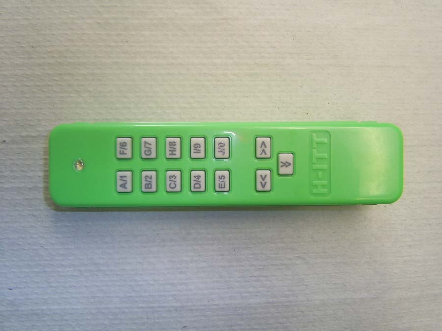
REMOTE - FCC ID UH9TX3000 - H-ITT, LLC
UH9TX3000

REMOTE

Nov 07, 2006

Equipment Class

DXX - Part 15 Low Power Communication Device Transmitter