UIQE1000FlipStart E-1000 Series
Vulcan Portals Inc.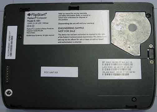
Click to zoom
Application Details
- Equipment Class
- PCB - PCS Licensed Transmitter
- Date of Grant
- Mar 25, 2007
- Application Purpose
- Original Equipment
- Date of Application
- Mar 08, 2007
- Equipment Note
- FlipStart E-1000 Series
- Frequency Range
- 1851.25000000 - 1908.75000000
- Company
- Vulcan Portals Inc.
- Country
- United States
Documents & Files
Document Text
Text extracted from the exhibit documents filed with the FCC. Open a document above to read the original.
Users Manual
User Guide © 2007 FlipStart Labs. All rights reserved. Reproduction of any part of this manual without the prior written permission of Vulcan Portals Inc. is strictly prohibited. Information in this document is subject to change without notice. Screen images simulated. Actual product may differ. FlipStart, the FlipStart logo, InfoPane, FlipStart Navigator, FlipStart Zoom, and FlipStart Control Center are trademarks of Vulcan Portals Inc. Microsoft, Windows, Vista and Outlook are trademarks of Microsoft Corporation. The Bluetooth word mark and logos are owned by the Bluetooth SIG, Inc. and any use of such marks by Vulcan Portals Inc. is under license. Other trademarks and trade names in this document refer to the entities claiming the marks and names or their products. FlipStart Labs disclaims any proprietary interest in trademarks and trade names other than its own. The FlipStart ® device, accessories bearing the FlipStart logo and FlipStart proprietary software are protected by copyright, international treaties and patents, including the following U.S. patents: 6,839,231 and 6,977,811. Additional patents are registered or pending in countries around the world. Part no. 600-0118-01 i Contents Introduction 1 Typographical conventions and icons used in this manual ........................................................... 2 Safety precautions .............................................................................................................................................. 3 General precautions ............................................................................................................................... 3 AC adapter.................................................................................................................................................. 4 Batteries ....................................................................................................................................................... 4 Airplane travel and hospitals ............................................................................................................. 4 Using FlipStart Help Central ........................................................................................................................... 5 Getting help from FlipStart ............................................................................................................................. 6 Getting to know your FlipStart 7 Welcome to FlipStart! ....................................................................................................................................... 7 The productivity of a PC ...................................................................................................................... 7 Familiar form factor ............................................................................................................................... 7 Easy access ................................................................................................................................................ 7 Straightforward connectivity ............................................................................................................ 7 What's in the box? ............................................................................................................................................... 9 Front view with display open ...................................................................................................................... 10 Top view with display closed ....................................................................................................................... 12 Right side view ..................................................................................................................................................... 13 Back view ............................................................................................................................................................... 14 Setting up 15 Quick Start ............................................................................................................................................................ 16 Turning the FlipStart on for the first time .............................................................................................. 17 Charging the battery before using unplugged .......................................................................18 How to hold the FlipStart .............................................................................................................................. 19 Using input devices .......................................................................................................................................... 20 Using the keyboard ............................................................................................................................. 20 Using the mouse controls ................................................................................................................ 23 Direction pad (D-pad) ....................................................................................................................... 23 Zoom key .................................................................................................................................................. 24 Using the Jog Dial ................................................................................................................................ 24 Getting connected to the Internet ........................................................................................................... 26 Connecting for the first time .......................................................................................................... 26 Configuring Wi-Fi (802.11b/g) wireless networking ........................................................... 26 Configuring cellular wireless broadband networking .........…
Text truncated - open the document above for the full version.
Cover Letter(s)
Appendix A Non-Conformities for US Radio Equipment Authorization Non-Conformities FCC ID: UIQE 1000 (CKC CS Ref # E07-000020-01) The items listed below represent requests for information following review of this application for certification under United S tates (FCC) regulations. . Further question may arise pending review of responses to these items. OK # Non-Conformity or Co mment Submitted Response Respondent / Date of Response Part 15 Devices X 1 The confidentiality letter provided includes a request for temporary confidentiality for test setup photos an d label placement. These items are not allowed to be held confidential in accordance with DA04-1705. Please provide a revised temporar y confidentiality letter. Temporary confidentiality request repealed CKC Labs 3/13/07 X 2 Temporary Confidentiality letter includes a reference to DA04-170. This document is not a valid reference. This appears to be a typo, please clarify. Temporary confidentiality request repealed CKC Labs 3/13/07 X 3 From the internal photos, it appears that the antennas are located near the bottom front of the equipment. Antenna positioning during testing appears to have equipment antenna near RF absorp ing material. Please clarify whether maximum emissions were measured from equipment under test while EUT antennas are separated from the table. Only LAN and BT cards have antennas in the bottom of the host; WAN antennas are in the lid. Test lab remeasured spurious emissions from host with device raised off the table. CKC Labs 3/13/07 X 4 Compliance with 15.247(e) is unclear. There are several plots included in the report however, they are not normalized to 3kHz bandwidth. Please clarify purpose of plots on pages 35 – 52. Compliance appears to have been met with plots on pages 53-58. Updated test report provided CKC Labs 3/13/07 X 5 Additionally, Bluetooth devices are not required to meet 15.247(e); plesae clarify intent of the plots included on pages 59 – 61. Updated test report provided CKC Labs 3/13/07 X 6 Please clarify version of Bluetooth used and type of modulation investigated during testing. Bluetooth Version: 2.0 +EDR Modulation: 8DPSK (enhanced data rate) CKC Labs 3/13/07 X 7 Please clarify compliance with 15.2 7, special accessories. The use of shielded cables is specified in the us ers manual on page 82. Please provide evidence or statement(s) of compli ance with this part. REFERENCE Excperpt:”§ 15.27 Special accesso ries. (a) Equipment marketed to a consumer must be capable of complying with the necessary regulations in the Updated users manual provided. “Shielded cables were not used.” CKC Labs 3/13/07 configuration in which th e equipment is marketed. Where special accessories, such as shielded cables and/or special connectors, are required to enable an unintentional or intentional radiator to comply with the emission limits in this part, the equipment must be marketed with, i.e., shipped and sold with, those special accessories. ” Part 22/24 Device X 8 Operational description for the part 22/24 radio is not included, please provide. Operational description provided. CKC Labs 3/13/07 X 9 Please clarify available modes of opera tion. Ie, does the device operate in modes other than CDMA? WAN is CDMA only. (1XEVDO) CKC Labs 3/13/07 X 10 From the internal photos, it appears that the antennas are located near the bottom front of the equipment. Antenna positioning during testing appears to have equipment antenna near RF absorp ing material. Please clarify whether maximum emissions were measured from equipment under test while EUT antennas are separated from the table. See item 3 above. CKC Labs 3/13/07 RF Exposure X 11 The RF power output is not consistent between the EMC and SAR reports: Please explain why RFX report indicates conducted output power for part 24E lower than the EMC report. Pleas e explain why RFX report indicates conducted output power for part 22H and 15C higher than EMC report.. Revised RF Exposure report provided. CKC CS notes that the conducted power output is in good agreement between test reports. CKC Labs 3/13/07 X 12 Page 1 of SAR report indicates FCC part 15 E rule part. Please confirm whether part 15C testing was performed. Revised RF Exposure report provided. CKC Labs 3/13/07 X 13 The RF Exposure Report (part 1 page 20) indicates testing only on channel 6 for 802.11b/g. Please clarify how compliance to FCC 802.11b/g SAR measurement procedures have been satisfied (REF 80211-SAR-1006 rev1d1.pdf updated OCT 2006) with channels 1 and 11. Revised RF Exposure report provided. CKC Labs 3/13/07 NC 14 TCB cannot locate RF Exposure stat ement in Users manual. Please provide an updated users manual including necessary warning statements. See NC-2 X 15 Specific Device operating conditions do not appear to be defined for the 802.11 / Bluetooth device; please clarify operating conditions for this test. Revised RF Exposure report provided. CKC Labs 3/13/07 General X 16 The schematics, block diagrams and operational descriptions must be provided for the WAN module as well as the BT and LAN devices. Please provide all necessary documents in accordance with 2.1033. Documents provided. CKC Labs 3/13/07 NC 17 Please provide updated test setup photos exhibit showing revised testing with the device off the table. See NC-2 X 18 Please clarify power output measurements: power output to be listed on part 22 and 24 reports is ERP and EIPR respectively. The test reports do not specify. Updated test reports provided CKC Labs 3/21/07 Non-Conformities FCC ID: UIQE 1000 (CKC CS Ref # E07-000020-02) The items listed below represent requests for information following review of this application for certification under United S tates (FCC) regulations. . Further question may arise pending review of responses to these items. OK # Non-Conformity or Co mment Submitted Response Respondent / Date of Response X 1 NC-01Item 14 not closed: TCB cannot locate RF Exposure statement in Users manual. Please provide an updated…
Text truncated - open the document above for the full version.
Cover Letter(s)
Date: February 21, 2007 CKC Certification Services 4933 Sierra Pines Dr. Mariposa, CA 95338 Attn: TCB Manager Ref: FCC ID: UIQE1000 Applicant: Vulcan Portals Inc. Dear Examiner, Sierra Wireless Inc., hereby authorize Vulcan Portals Inc., to use the Conducted Test report exhibit filed by Sierra Wireless with the FCC for FCCID: N7N-MC5725. Reference Report #06U10171-1 (May 12, 2006). The conducted test data from this report may be reproduced in certification filing by Vulcan Portals Inc., on all applicable products that contain this module. If you have any questions regarding this authorization, please feel free to contact me. Sincerely, Todd Van Cleave Manager, Engineering Services Carlsbad Research & Development Sierra Wireless America, Inc.
External Photos
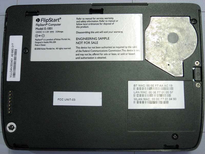
Front Back with port replicator Back with no port replicator Top Top with port replicator Bottom with port replicator Bottom Battery on Bottom battery removed Left Left with port replicator Right Right with port replicator
RF Exposure Info
© 2006 RF Exposure Lab, LLC This report shall not be reproduced except in full without the written approval of RF Exposure Lab, LLC. 2867 Progress Place, Suite 4D • Escondido, CA 92029 • U.S.A. TEL (760) 737-3131 • FAX (760) 737-9131 http://www.rfexposurelab.com CERTIFICATE OF COMPLIANCE SAR EVALUATION Vulcan Portals Inc. Dates of Test: February 21-23, 2007 505 Fifth Ave. S Test Report Number: SAR.20070201 Seattle, WA 98104 This wireless mobile and/or portable device has been shown to be compliant for localized specific absorption rate (SAR) for uncontrolled environment/general exposure limits specified in ANSI/IEEE Std. C95.1-1999 and had been tested in accordance with the measurement procedures specified in IEEE 1528-2003, OET Bulletin 65 Supp. C, RSS-102 and Safety Code 6 (See test report). I attest to the accuracy of the data. All measurements were performed by myself or were made under my supervision and are correct to the best of my knowledge and belief. I assume full responsibility for the completeness of these measurements and vouch for the qualifications of all persons taking them. RF Exposure Lab, LLC certifies that no party to this application has been denied FCC benefits pursuant to Section 5301 of the Anti-Drug Abuse Act of 1988, 21 U.S.C. 853(a). Jay M. Moulton Vice President Certificate # 2387.01 FCC ID: UIQE1000 Model(s): FlipStart Computer Model: E-1001 Test Sample: Pre-Production Unit same as Production Serial No.: 6BD01Y Equipment Type: Wireless Computer Classification: Portable Transmitter Next to Body TX Frequency Range: 824.7 – 848.31 MHz, 1851.25 – 1908.75 MHz, 2412 – 2462 MHz Frequency Tolerance: ± 25 ppm Maximum RF Output: 835 MHz – 25.15 dBm, 1900 MHz – 24.83 dBm 2450 MHz – 14.09 dBm Signal Modulation: DSSS, OFDM, CDMA Antenna Type (Length): Internal 2450 MHz(Universal Scientific Industrial Co., Ltd P/N 200-0038-01{Main}, 200-0039-01{Aux}), 835/1900 MHz(Located on Mother Board) Battery: Std. (Vulcan P/N 200-0026-xx), Ext. (Vulcan P/N 200-0251-xx) Battery Pack Application Type: Certification FCC Rule Parts: Part 15C, 22, 24 FCC ID: UIQE1000 © 2006 RF Exposure Lab, LLC Page 2 of 224 This report shall not be reproduced except in full without the written approval of RF Exposure Lab, LLC. Table of Contents 1. Introduction ...........................................................................................................................3 SAR Definition [5]......................................................................................................................3 2. SAR Measurement Setup .....................................................................................................4 Robotic System .........................................................................................................................4 System Hardware .....................................................................................................................4 System Description ...................................................................................................................4 E-Field Probe ALS-E-020 ......................................................................................................... 5 3. Robot Specifications .............................................................................................................7 4. Probe and Dipole Calibration ................................................................................................8 5. Phantom & Simulating Tissue Specifications........................................................................9 SAM Phantom ...........................................................................................................................9 Brain & Muscle Simulating Mixture Characterization ................................................................9 Device Holder ...........................................................................................................................9 6. Definition of Reference Points.............................................................................................10 Ear Reference Point................................................................................................................10 Device Reference Points ........................................................................................................10 7. Test Configuration Positions ...............................................................................................11 Positioning for Cheek/Touch [5] ..............................................................................................11 Positioning for Ear / 15 ̊ Tilt [5]................................................................................................12 Body Worn Configurations ......................................................................................................13 8. ANSI/IEEE C95.1 – 1999 RF Exposure Limits [2]...............................................................14 Uncontrolled Environment.......................................................................................................14 Controlled Environment .......................................................................................................... 14 9. Measurement Uncertainty ...................................................................................................15 10. System Validation ........................................................................................................... 16 Tissue Verification...................................................................................................................16 Test System Verification ......................................................................................................... 16 11. SAR Test Data Summary ................................................................................................18 Procedures Used To Establish Test Signal................…
Text truncated - open the document above for the full version.
RF Exposure Info
FCC ID: UIQE1000 © 2006 RF Exposure Lab, LLC Page 151 of 224 This report shall not be reproduced except in full without the written approval of RF Exposure Lab, LLC. PWB Circuit Side With LAN Module Shielding Below Keyboard FCC ID: UIQE1000 © 2006 RF Exposure Lab, LLC Page 152 of 224 This report shall not be reproduced except in full without the written approval of RF Exposure Lab, LLC. PWB Circuit Side LAN Module in Place FCC ID: UIQE1000 © 2006 RF Exposure Lab, LLC Page 153 of 224 This report shall not be reproduced except in full without the written approval of RF Exposure Lab, LLC. LAN Module Back LAN Module Front FCC ID: UIQE1000 © 2006 RF Exposure Lab, LLC Page 154 of 224 This report shall not be reproduced except in full without the written approval of RF Exposure Lab, LLC. Cover Removed Behind LCD With WAN Module Module On PCB FCC ID: UIQE1000 © 2006 RF Exposure Lab, LLC Page 155 of 224 This report shall not be reproduced except in full without the written approval of RF Exposure Lab, LLC. WAN Module Back WAN Module Front FCC ID: UIQE1000 © 2006 RF Exposure Lab, LLC Page 156 of 224 This report shall not be reproduced except in full without the written approval of RF Exposure Lab, LLC. Standard Battery Front Standard Battery Back FCC ID: UIQE1000 © 2006 RF Exposure Lab, LLC Page 157 of 224 This report shall not be reproduced except in full without the written approval of RF Exposure Lab, LLC. Extended Battery Front Extended Battery Back FCC ID: UIQE1000 © 2006 RF Exposure Lab, LLC Page 158 of 224 This report shall not be reproduced except in full without the written approval of RF Exposure Lab, LLC. Appendix D – Probe Calibration Data Sheets NCL CALIBRATION LABORATORIES Calibration File No.: CP-681 Client.: RFEL C E R T I F I C A T E OF C A L I B R A T I O N It is certified that the equipment identified below has been calibrated in the NCL CALIBRATION LABORATORIES by qualified personnel following recognized procedures and using transfer standards traceable to NRC/NIST. Equipment: Miniature Isotropic RF Probe 835 MHz BODY Calibration Manufacturer: APREL Laboratories Model No.: E-020 Serial No.: 217 Calibration Procedure: SSI/DRB-TP-D01-032-E020-V2 Project No: RFEB-E020CAL-5232 Calibrated: 30 th May 2006 Released on: 2 nd June 2006 APREL Laboratories Certified Under Laboratory 48 of SCC NCL CALIBRATION LABORATORIES 51 SPECTRUM WAY Division of APREL Lab. NEPEAN, ONTARIO TEL: (613) 820-4988 CANADA K2R 1E6 FAX: (613) 820-4161 NCL Calibration Laboratories Division of APREL Laboratories. Page 2 of 10 This page has been reviewed for content and attested to on Page 2 of this document. Introduction This Calibration Report reproduces the results of the calibration performed in line with the SSI/DRB-TP-D01-032-E020-V2 E-Field Probe Calibration Procedure. The results contained within this report are for APREL E-Field Probe E-020 217. References SSI/DRB-TP-D01-032-E020-V2 E-Field Probe Calibration Procedure IEEE 1528 “Recommended Practice for Determining the Peak Spatial-Average Specific Absorption Rate (SAR) in the Human Body Due to Wireless Communications Devices: Experimental Techniques” SSI-TP-011 Tissue Calibration Procedure IEC 62209 “Human exposure to radio frequency fields from hand-held and body- mounted wireless communication devices – Human models, instrumentation, and procedures –Part 1 & 2: Procedure to determine the Specific Absorption Rate (SAR) for hand-held devices used in close proximity of the ear (frequency range of 300 MHz to 3 GHz)” IEEE 1309 Draft Standard for Calibration of Electromagnetic Field Sensors and Probes, Excluding Antennas, from 9kHz to 40GHz Conditions Probe 217 was a re-calibration. Ambient Temperature of the Laboratory: 22 °C +/- 0.5°C Temperature of the Tissue: 21 °C +/- 0.5°C NCL Calibration Laboratories Division of APREL Laboratories. Page 3 of 10 This page has been reviewed for content and attested to on Page 2 of this document. Calibration Results Summary Probe Type: E-Field Probe E-020 Serial Number: 217 Frequency: 835 MHz Sensor Offset: 1.56 mm Sensor Length: 2.5 mm Tip Enclosure: Ertalyte* Tip Diameter: <5 mm Tip Length: 60 mm Total Length: 290 mm *Resistive to recommended tissue recipes per IEEE-1528 Sensitivity in Air Channel X: 1.2 μV/(V/m) 2 Channel Y: 1.2 μV/(V/m) 2 Channel Z: 1.2 μV/(V/m) 2 Diode Compression Point: 95 mV NCL Calibration Laboratories Division of APREL Laboratories. Page 4 of 10 This page has been reviewed for content and attested to on Page 2 of this document. Sensitivity in Body Tissue Frequency: 835 MHz Epsilon: 55.2 (+/-5%) Sigma: 1.05 S/m (+/-10%) ConvF Channel X: 6.1 Channel Y: 6.1 Channel Z: 6.1 Tissue sensitivity values were calculated using the load impedance of the APREL Laboratories Daq-Paq. Boundary Effect: Uncertainty resulting from the boundary effect is less than 2% for the distance between the tip of the probe and the tissue boundary, when less than 2.44mm. Spatial Resolution: The measured probe tip diameter is 5 mm (+/- 0.01 mm) and therefore meets the requirements of SSI/DRB-TP-D01-032 for spatial resolution. NCL Calibration Laboratories Division of APREL Laboratories. Page 5 of 10 This page has been reviewed for content and attested to on Page 2 of this document. Receiving Pattern 835 MHz (Air) Receiving Pattern Probe s/n 217 835MHz 0 0.2 0.4 0.6 0.8 1 1.2 0 10 20 30 40 50 60 70 80 90 100 110 120 130 140 150 160 170 180 190 200 210 220 230 240 250 260 270 280 290 300 310 320 330 340 350 Ch1Ch2Ch3Tot NCL Calibration Laboratories Division of APREL Laboratories. Page 6 of 10 This page has been reviewed for content and attested to on Page 2 of this document. Isotropy Error 835 MHz (Air) Isotropy Error Probe s/n 217 835MHz -10 -9 -8 -7 -6 -5 -4 -3 -2 -1 0 1 2 3 4 5 6 7 8 9 10 0100200300 Error [dB] Isotropy Plot Probe s/n 217 835MHz 0 0.1 0.2 0.3 0.4 0.5 0.6 0.7 0.8 0100200300 Degrees (x10) Voltage (mV) Ch1Ch2Ch3 Isotropicity Tissue: 0.10 dB NCL Calibration Laboratories Division of APREL Laboratories. Page 7 of 10 T…
Text truncated - open the document above for the full version.
Test Report
Page 1 of 14 Report No.: FC07-011A ADDENDUM TO VULCAN PORTALS, INC. TEST REPORT FC07-011 FOR THE FLIPSTART E-1000 SERIES FCC PART 22 COMPLIANCE DATE OF ISSUE: MARCH 21, 2007 PREPARED FOR: Vulcan Portals, Inc. 505 5th Ave. South, Ste. 900 Seattle, WA 98104 PREPARED BY: Mary Ellen Clayton CKC Laboratories, Inc. 5046 Sierra Pines Drive Mariposa, CA 95338 P.O. No.: 2018500907 W.O. No.: 86066 Date of test: January 29-31, 2007 Report No.: FC07-011A This report contains a total of 14 pages and may be reproduced in full only. Partial reproduction may only be done with the written consent of CKC Laboratories, Inc. The results in this report apply only to the items tested, as identified herein. Page 2 of 14 Report No.: FC07-011A TABLE OF CONTENTS Administrative Information .............................................................................................3 Conditions for Compliance ..............................................................................................4 Approvals .........................................................................................................................4 Equipment Under Test (EUT) Description ......................................................................4 Equipment Under Test .....................................................................................................5 Peripheral Devices ...........................................................................................................5 Temperature and Humidity During Testing.....................................................................6 FCC 2.1033(c)(3) User’s Manual ....................................................................................6 FCC 2.1033(c)(4) Type of Emissions ..............................................................................6 FCC 2.1033(c)(5) Frequency Range................................................................................6 FCC 2.1033(c)(6) Operating Power.................................................................................6 FCC 2.1033(c)(7) Maximum Power Rating ....................................................................6 FCC 2.1033(c)(8) DC Voltages .......................................................................................6 FCC 2.1033(c)(9) Tune-Up Procedure ............................................................................6 FCC 2.1033(c)(10) Schematics and Circuitry Description..............................................6 FCC 2.1033(c)(11) Label and Placement ........................................................................6 FCC 2.1033(c)(12) Submittal Photos ..............................................................................6 FCC 2.1033(c)(13) Modulation Information ...................................................................6 FCC 2.1033(c)(14)/2.1046/22.913 - RF Power Output ...................................................7 FCC 22.917 Bandedge .....................................................................................................9 FCC 2.1033(c)(14)/2.1053/22.917(a) - Field Strength of Spurious Radiation ................13 Page 3 of 14 Report No.: FC07-011A ADMINISTRATIVE INFORMATION DATE OF TEST: January 29-31, 2007 DATE OF RECEIPT: January 29, 2007 FREQUENCY RANGE TESTED: 1-10 GHz MANUFACTURER: Universal Scientific Industrial Co., Ltd. 141, Lane 351, Taiping Road, Sec. 1 Tsao Tuen, Nan-Tou, Taiwan REPRESENTATIVE: Daniel Oar TEST LOCATION: CKC Laboratories, Inc. 22116 23rd Drive S.E., Suite A Bothell, WA 98021-4413 TEST METHOD: FCC Part 22 PURPOSE OF TEST: Original Report: To demonstrate the compliance of the FlipStart E-1000 series with the requirements for FCC Part 22 devices. Addendum A: To clarify the RF Power output on page 7 with no new testing. Page 4 of 14 Report No.: FC07-011A CONDITIONS FOR COMPLIANCE No modifications to the EUT were necessary to comply. APPROVALS Steve Behm, Director of Engineering Services QUALITY ASSURANCE:TEST PERSONNEL: Joyce Walker, Quality Assurance Administrative Manager Ryan Rutledge, Test Technologist Katie Molina, Senior EMC Engineer/Lab Manager EQUIPMENT UNDER TEST (EUT) DESCRIPTION The customer declares the EUT tested by CKC Laboratories was representative of a production unit. FlipStart is a super compact PC with the form factor that’s proven to work for mobile professionals, including everything you expect from your laptop – effortless application usage, communications, entertainment and Internet connectivity. Its familiar clamshell design is packed with innovative features that deliver unprecedented flexibility and productivity to mobile users. Built on the Intel platform, FlipStart has a QWERTY thumb keypad, 1024 X 600 high-resolution 5.6" display in a protective clamshell design. Built-in WiFi and Bluetooth®, and multiple carrier 3G WAN support allow users to stay connected. The following model was tested by CKC Laboratories: FlipStart Computer, E-1001 The customer declares that the actual model tested was E-1001s…
Text truncated - open the document above for the full version.
Contact Information
Applicant
Daniel Oar
Technical Contact
CKC Laboratories, Inc.Mary Ellen Clayton
[email protected]209-742-6133
5046 Sierra Pines Drive · Mariposa, California · United States
Non-Technical Contact
CKC Laboratories, Inc.Mary Ellen Clayton
[email protected]209-966-5240
Test Firm
CKC Laboratories, Inc.Steve Behm
Technical Specifications
| # | Rule Parts | Frequency Range | Power Output | Emission | Tolerance |
|---|---|---|---|---|---|
| 2 | 24E | 1.85 GHz - 1.91 GHz | 1.07 W | 1M40F9W | 2.5 ppm |
Other Applications from Vulcan Portals Inc.
UIQE1500
Dec 20, 2007FlipStart E-1500 series with HSDPA
Equipment Class
DTS - Digital Transmission System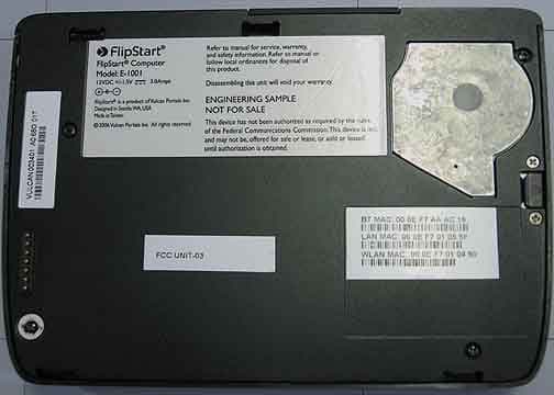
UIQE1WR0
Mar 25, 2007FlipStart E-1000 Series
Equipment Class
DSS - Part 15 Spread Spectrum Transmitter