UJYMS0100MicroSync Transmitter & Receiver
Tamrac, Inc.
Click to zoom
Application Details
- Equipment Class
- DSC - Part 15 Security/Remote Control Transmitter
- Date of Grant
- Sep 14, 2006
- Application Purpose
- Original Equipment
- Date of Application
- Sep 12, 2006
- Equipment Note
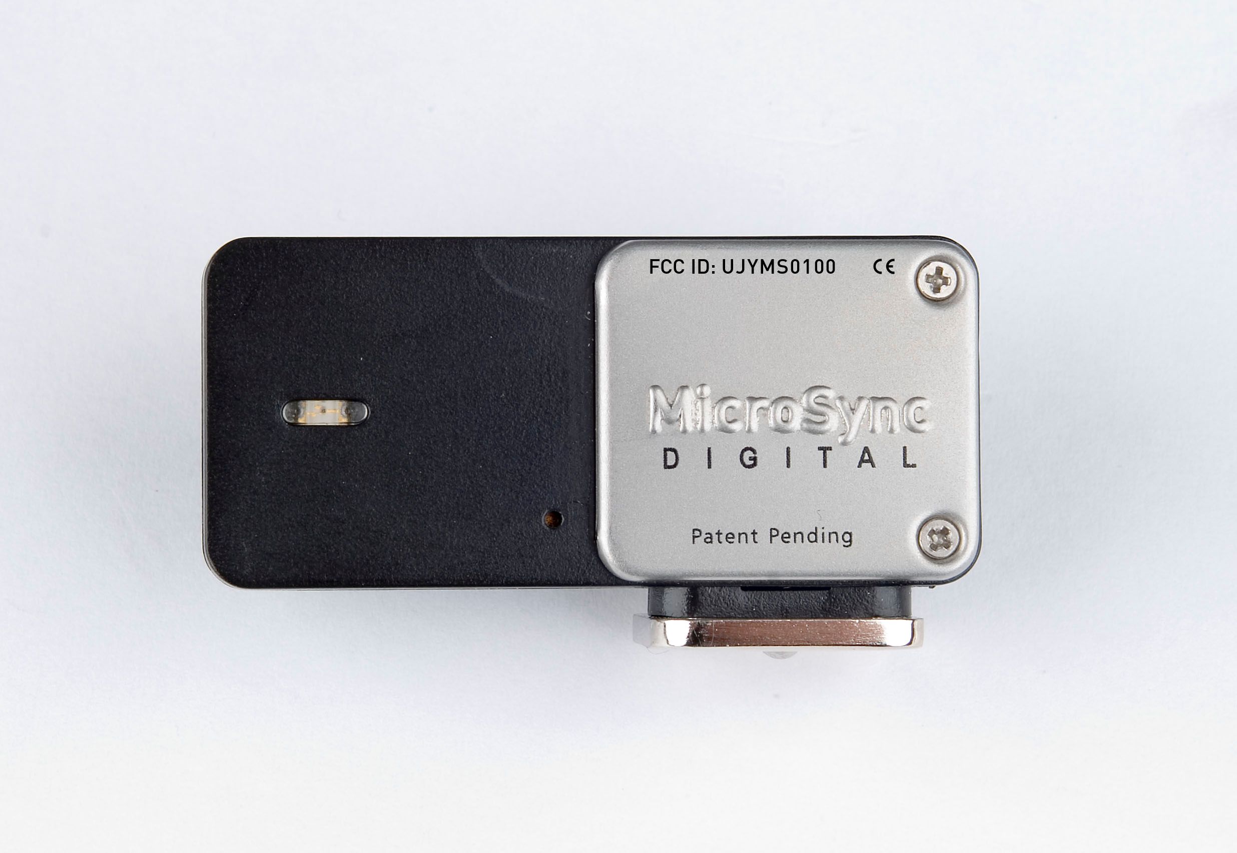
- MicroSync Transmitter & Receiver
- Frequency Range
- 433.90000000 - 433.90000000
- Company
- Tamrac, Inc.
- Country
- United States
Documents & Files
Document Text
Text extracted from the exhibit documents filed with the FCC. Open a document above to read the original.
Users Manual
083006 1130 MicroSync User’s Guide Thank you for purchasing the MicroSync Digital – the smallest, smartest wireless solution for triggering strobes and cameras. It is built to exacting standards to provide years of professional-level, creative work. Directions To Fire Strobes To fire strobe lights using the MicroSync, you need a MicroSync transmitter and a MicroSync receiver. Follow these easy steps: 1. Insert the transmitter into the hot shoe of your camera (if your camera doesn’t have a hot shoe, visit www.microsyncdigital.com to learn how to fire strobes without a hot shoe). 2. Open the receiver battery compartment by pulling down on the slotted side of the receiver. 3. Install the 2 included “AA” batteries (observe the polarity of the batteries as indicated). 4. Plug the receiver into the sync socket of your power pack or monolight. If the plugs are not compatible, you can connect the receiver with a cable. Visit www.microsyncdigital.com for information about cables. 5. Shoot! Changing Channels The MicroSync has 4 channels. To operate, the transmitter and receiver must be on the same channel. Both the transmitter and the receiver are set to channel 1 at the factory. The receiver also automatically resets to channel 1 when the batteries are removed and re-installed. To change the channel, follow these steps: 1. Plug the receiver into the sync socket of the power pack or monolight, with the strobe turned on. 2. Stand within three feet of the receiver. 3. Firmly insert the end of a paper clip into the channel select opening to set the transmitter to the next channel. This must be done within 10 seconds of plugging in the receiver. The transmitter’s LED will flash to confirm your channel selection. For example, when the transmitter is set to channel 3, the LED will blink 3 times to confirm this channel selection. The transmitter will automatically synchronize the receiver to the channel you select. The receiver’s LED will simultaneously flash to confirm your channel selection. Please note that after 10 seconds, the receiver will lock itself to the last selected channel. This feature ensures that another MicroSync user cannot inadvertently change the channel of your MicroSync receiver. Tips and troubleshooting My MicroSync won’t fire. The most common reasons are unsynchronized channels or dead batteries. Test the strobe independently to be sure it is firing. If the strobe works, but the MicroSync doesn’t, turn the strobe off and on again with the receiver connected. The receiver should blink to confirm startup. If not, replace the batteries, observing the polarity. Within 10 seconds after the receiver startup confirmation, firmly insert the end of a paper clip into the channel select opening to synchronize the channels (transmitter must be within three feet of receiver). The transmitter LED should blink to confirm the channel selection. If not, replace the battery, observing the polarity. I can’t get enough range. The MicroSync has been tested to 100 feet. Radio reflections and obstructions may reduce the range significantly, so observe the following guidelines to achieve the best range: Position the receiver antenna vertically, and as high as possible. Keep your hands from covering the transmitter antenna. Avoid having metal, concrete, or water obstructions between the transmitter and receiver. Relocate the receiver to avoid possible local reflections. Often moving the transmitter a few feet will solve the problem. Remotely Trigger Cameras (cables required) With the addition of an accessory cable (not included), the MicroSync transmitter and receiver can be used to remotely trigger most cameras. The camera that you have determines the cable that you need. Your camera must have an electronic shutter release input (which most modern, professional cameras have). You will also need a special cable to connect the MicroSync receiver to your camera’s electronic shutter release input. For information about which cable is right for your camera, please visit our website at www.microsyncdigital.com. Once you obtain the proper cable, follow these easy steps: 1. Locate the electronic shutter release input on your camera. 2. Plug the corresponding end of the cable into the camera’s electronic shutter release input. 3. Plug the cable’s sub mini phone plug into the MicroSync receiver output. 4. Holding the transmitter, press the test fire button to fire the camera. Please Note: For cameras with a “pre-focus” feature, you will need to press the test fire button for a couple seconds for the camera to focus and then fire. 083006 1130 Specifications: Transmitter Batteries / approx. life: CR2032 / 3 yrs Plugs: hotfoot 2.5 mm Ports: sub-mini phono input Size: 27 x 51 x 11 mm Weight incl. Batteries: 30 g Max range: 100 ft Max sync speed: 1/180 sec Channels: 4 Frequency: 433 MHz Receiver Batteries / approx. life: 2 AA / 1 yr Plugs: mono plug or household plug Ports: sub-mini phono output Size: 35 x 111 x 22 mm Weight incl. Batteries: 180 g 1 YEAR LIMITED WARRANTY This MicroSync™ Digital product is fully warranted to the original retail purchaser against defects in materials and workmanship for 1 year, except as noted below. This warranty shall apply to those products which have been put to the use intended by the manufacturer and does not apply to products damaged by misuse or neglect. Service under this warranty is available by forwarding the product freight prepaid, with dated proof of purchase to Tamrac’s Service Department, 9240 Jordan Avenue, Chatsworth, CA 91311, USA. If our inspection finds the product to be defective in either materials or workmanship, we will repair or replace it at our option and return it freight collect. This procedure shall be the exclusive remedy for any breach of this limited warranty. Tamrac shall not be liable for consequential or incidental damages. There are no other expressed or implied warranties, including merchantability or fitness for particular purpose, that extend beyo…
Text truncated - open the document above for the full version.
Cover Letter(s)
August 22, 2006 American TCB 6731 Whittier Avenue, Suite C110 McLean, VA. 22101 Gentlemen: The enclosed documents constitute a formal submittal and application for a Grant of Equipment Authorization pursuant to the following: Subpart B of Part 15 of FCC Rules (CFR 47) – Requirements for receivers Subpart C of Part 15 of FCC Rules (CFR 47) Data within this report demonstrates that the equipment tested complies with the relevant limits for unlicensed wireless devices. Please note that a grant for limited modular approval is being requested. Elliott Laboratories, as duly authorized agent prepared this submittal. A copy of the letter of our appointment as agent is enclosed. If there are any questions or if further information is needed, please contact Elliott Laboratories for assistance. Sincerely, Mark Briggs Principal Engineer MB/dmg Enclosures: Agent Authorization Letter Emissions Test Report with Exhibits
Test Report
File: R65067, Rev. 1 Page 1 of 20 2016-01 Electromagnetic Emissions Test Report and Application for Grant of Equipment Authorization pursuant to FCC Part 15 Subpart C on the Tamrac Transmitter Model: MicroSync Transmitter and Receiver FCC ID: UJYMS0100 GRANTEE: Tamrac 9240 Jordan Avenue Chatsworth, CA 91311 TEST SITE: Elliott Laboratories, Inc. 684 W. Maude Ave Sunnyvale, CA 94086 REPORT DATE: August 22, 2006 FINAL TEST DATE: March 22 and March 24, 2006 AUTHORIZED SIGNATORY: ______________________________ Mark Briggs Principal Engineer Elliott Laboratories, Inc. is accredited by the A2LA, certificate number 2016-01, to perform the test(s) listed in this report. This report shall not be reproduced, except in its entirety, without the written approval of Elliott Laboratories, Inc. Elliott Laboratories, Inc. -- EMC Department Test Report Report Date: August 22, 2006 File: R65067, Rev. 1 Page 2 of 20 pages REVISION HISTORY Revision # Date Comments Modified By 1 September 8, 2006 Initial Release David Guidotti Elliott Laboratories, Inc. -- EMC Department Test Report Report Date: August 22, 2006 File: R65067, Rev. 1 Page 3 of 20 pages \ TABLE OF CONTENTS COVER PAGE............................................................................................................................................................. 1 Elliott Laboratories, Inc. -- EMC Department Test Report Report Date: August 22, 2006 File: R65067, Rev. 1 Page 4 of 20 pages SCOPE An electromagnetic emissions test has been performed on the Tamrac model MicroSync Transmitter and Receiver pursuant to the following rules: FCC Part 15 Subpart B (Receivers) FCC Part 15 Subpart C FCC Part 15 Subpart C requirements for momentarily operated devices Conducted and radiated emissions data has been collected, reduced, and analyzed within this report in accordance with measurement guidelines set forth in the following reference standards and as outlined in Elliott Laboratories test procedures: ANSI C63.4:2003 The intentional radiator above has been tested in a simulated typical installation to demonstrate compliance with the relevant Industry Canada performance and procedural standards. Final system data was gathered in a mode that tended to maximize emissions by varying orientation of EUT, orientation of power and I/O cabling, antenna search height, and antenna polarization. Every practical effort was made to perform an impartial test using appropriate test equipment of known calibration. All pertinent factors have been applied to reach the determination of compliance. The test results recorded herein are based on a single type test of the Tamrac model MicroSync Transmitter and Receiver and therefore apply only to the tested sample. The sample was selected and prepared by Paul Finkel of Paul Finkel Consulting Elliott Laboratories, Inc. -- EMC Department Test Report Report Date: August 22, 2006 File: R65067, Rev. 1 Page 5 of 20 pages OBJECTIVE The primary objective of the manufacturer is compliance with the regulations outlined in the previous section. Certification of these devices is required as a prerequisite to marketing in the US. The primary objective of the manufacturer is compliance with the regulations outlined in the previous section. Certification of these devices is required as a prerequisite to marketing in the US. Devices categorized as Class II equipment do not require certification by Industry Canada. Certification is a procedure where the manufacturer submits test data and technical information to a certification body and receives a certificate or grant of equipment authorization upon successful completion of the certification body’s review of the submitted documents. Once the equipment authorization has been obtained, the label indicating compliance must be attached to all identical units, which are subsequently manufactured. Maintenance of compliance is the responsibility of the manufacturer. Any modification of the product which may result in increased emissions should be checked to ensure compliance has been maintained (i.e., printed circuit board layout changes, different line filter, different power supply, harnessing or I/O cable changes, etc.). STATEMENT OF COMPLIANCE The tested sample of Tamrac model MicroSync Transmitter and Receiver complied with the requirements of the following regulations: FCC Part 15 Subpart B (Receivers) FCC Part 15 Subpart C FCC Part 15 Subpart C requirements for momentarily operated devices Maintenance of compliance is the responsibility of the manufacturer. Any modification of the product which may result in increased emissions should be checked to ensure compliance has been maintained (i.e., printed circuit board layout changes, different line filter, different power supply, harnessing or I/O cable changes, etc.). Elliott Laboratories, Inc. -- EMC Department Test Report Report Date: August 22, 2006 File: R65067, Rev. 1 Page 6 of 20 pages TEST RESULTS SUMMARY – MicroSync Transmitter MOMENTARILY OPERATED DEVICES – CONTROL SIGNALS FCC Part 15 Reference RSS Reference Description Measured Value / Comments Limit / Requirement Result 15.231 (a) (1) RSS 210 A1.1.1 (1) Duration of manually activated transmissions 350ms < 5 seconds Complies 15.231 (a) (2) RSS 210 A1.1.1 (2) Duration of automatically activated transmissions Not applicable - all transmissions manually activated. < 5 seconds Complies 15.231 (a) (3) RSS 210 A1.1.1 (3) Transmissions at predetermined / regular intervals No such transmissions Such transmissions are not permitted Complies 15.231 (a) (4) RSS 210 A1.1.1 (4) Pendency of transmissions used during emergencies No such transmissions Complies 15.231 (b) RSS 210 Table 4 Fundamental Signal Strength @ 433.9 MHz 71.1dBμ V/m (3589.2μ V/m) (-9.7dB) Complies 15.231 (b) / 15.209 RSS 210 Table 2 / 4 Radiated Spurious Emissions, 30 - 4300 MHz 79.4dBμ V/m (9375.6μ V/m) @ 2167.5MHz (-1.4dB) Complies 15.231 (c) RSS 210 A1.1.3 Bandwidth 250 kHz Complies 15.231 (d) RSS 210 A1.1.4 Frequency …
Text truncated - open the document above for the full version.
Test Setup Photos
Radiated Emissions Test Configuration Photographs Radiated Emissions Test Configuration Photographs
Contact Information
Applicant
Ryan J. Cyr(Executive Vice President)
Technical Contact
Elliott LabeJuan Martinez
[email protected]408 245 7800
684 West Maude Ave · Sunnyvale, California · United States
Test Firm
Elliott Laboratories Inc.David Bare
Technical Specifications
| # | Rule Parts | Frequency Range | Power Output |
|---|---|---|---|
| 1 | 15.231 | 433.9 MHz - 433.9 MHz | - |
Other Applications from Tamrac, Inc.
UJYMS0200
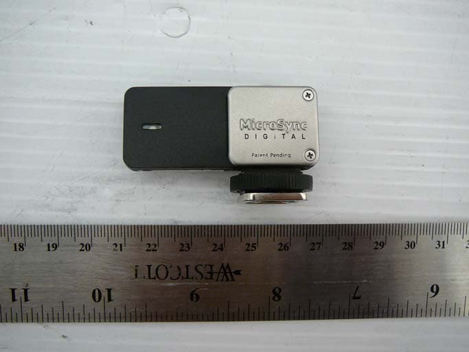
Sep 14, 2010Wireless radio controller to trigger cameras and/or strobes.
Equipment Class
DSC - Part 15 Security/Remote Control Transmitter