UKOTAG3THTag for EGOProSafe system
Advanced Microwave Engineering s.r.l.
Click to zoom
Application Details
- Equipment Class
- DSC - Part 15 Security/Remote Control Transmitter
- Date of Grant
- Feb 03, 2020
- Application Purpose
- Original Equipment
- Date of Application
- Feb 03, 2020
- Equipment Note
- Tag for EGOProSafe system
- Frequency Range
- 433.92000000 - 433.92000000
- Country
- Italy
Documents & Files
Document Text
Text extracted from the exhibit documents filed with the FCC. Open a document above to read the original.
Users Manual
EGOpro Safe MOVE 4.0 Use and Installation Manual (V01) TABLE OF REVISIONS 2 The technical materials and information contained in this document are strictly confidential and the exclusive property of Advanced Microwave Engineering s.r.l. These materials and information are intended solely for the purpose designated and may not be used otherwise. It is not permitted to disclose or reproduce them in whole or in part without express written permission. TABLE OF CONTENTS 1 TABLE OF REVISIONS 6 2 CONFORMITY 7 3 SAFETY INSTRUCTIONS 7 3.1 DISPOSAL 7 3.2 LIMITATIONS FOR USE 7 3.3 STATEMENTS FOR THE USE IN NORTH AMERICA 7 3.3.1 STATEMENTS FOR PLXSAFEMOVESENS4 AND PLXSAFEMOVESEN4M. 8 4 INTRODUCTION 8 4.1 INTENDED USE 8 4.2 SYMBOLS 8 5 BASIC KIT COMPONENTS 9 6 SYSTEM OPERATION 10 6.1 PEDESTRIAN WORKER PRE-WARNING 10 6.2 PEDESTRIAN WORKER WARNING 10 6.3 VEHICLE-VEHICLE WARNING 10 7 PLACING TAGS 11 7.1 HELMET TAG FITTING 11 7.2 WEARABLE TAG ACCESSORIES 11 7.3 PROCEDURE FOR CHANGING THE BATTERY 12 8 INSTALLATION ON THE VEHICLE 13 8.1 SYSTEM ARCHITECTURE AND GENERAL INSTRUCTIONS 13 8.2 POSITIONING THE DEVICES 15 8.2.1 POSITIONING THE CONTROL UNIT (CPU) 16 8.2.2 POSITIONING THE DISPLAY 17 8.2.3 POSITIONING THE SENSORS 17 8.2.4 POSITIONING THE HUB 18 8.3 CONNECTIONS 19 8.3.1 GENERAL INSTRUCTIONS 19 8.3.2 CPU WIRING 21 8.3.3 CONNECTING SENSORS 22 8.3.4 CONNECTING THE HUB 24 TABLE OF REVISIONS 3 The technical materials and information contained in this document are strictly confidential and the exclusive property of Advanced Microwave Engineering s.r.l. These materials and information are intended solely for the purpose designated and may not be used otherwise. It is not permitted to disclose or reproduce them in whole or in part without express written permission. 8.4 INSTALLING THE SYSTEM WITH M12 CONNECTORS 26 8.4.1 LENGTH OF CONNECTIONS 27 8.5 EXPANSION OF THE NUMBER OF SENSORS 28 8.6 STOPPING DISTANCES AND ACTIVATION DISTANCES 29 8.7 VEHICLE DECELERATION AND DRIVER'S RESPONSE DISTANCES 29 8.8 SYSTEM ACTIVATION DISTANCES. SETTING THE POWERS TRANSMITTED 31 8.9 CALCULATING THE DISTANCE IN CASE OF VEHICLE-VEHICLE COLLISION. 32 9 TURNING-ON AND CONFIGURATION 33 9.1 TURNING ON THE SYSTEM 33 9.2 CONFIGURATION 34 9.2.1 STEP 1 | CONFIGURATION MENU 34 9.2.2 STEP 2 | ENTERING THE PASSWORD 34 9.2.3 STEP 3 | SENSORS 35 9.2.4 STEP 4 | SENSORS SEARCH 36 9.2.5 STEP 5 | SEARCHING SENSORS BY ID 37 9.2.6 STEP 6 | SEARCHING SENSORS BY POSITION 40 9.2.7 SEARCHING SENSORS WITHOUT ID 41 9.3 TEST 41 9.3.1 SENSOR CHECK 41 9.3.2 TAG DETECTION TEST 42 10 OPERATION MODES 43 10.1 DISPLAY OVERVIEW 43 10.2 PEDESTRIAN WORKER’S TAG DISPLAY ALARM: PRE-WARNING 44 10.3 PEDESTRIAN WORKER’S TAG DISPLAY ALARM: WARNING 45 10.4 SENSORS AND HUB DIAGNOSIS 46 10.5 DRIVER LOGIN 47 10.6 DATA ACCESS 49 11 BASIC CONFIGURATION 50 11.1 ACCESS TO MENU 50 11.2 REBOOT 51 11.3 CONFIGURATION MENU 52 11.4 CLOCK & DATE 53 11.4.1 MANUAL 53 11.4.2 AUTOMATIC 54 11.5 ALARM CONFIGURATION 55 11.6 SENSORS CONFIGURATION 57 11.6.1 SENSORS SEARCH 57 11.6.2 SENSORS POWER 58 11.6.3 LR SENSORS POWER 59 11.6.4 SR SENSORS POWER 60 TABLE OF REVISIONS 4 The technical materials and information contained in this document are strictly confidential and the exclusive property of Advanced Microwave Engineering s.r.l. These materials and information are intended solely for the purpose designated and may not be used otherwise. It is not permitted to disclose or reproduce them in whole or in part without express written permission. 11.6.5 TAG SETTINGS 61 11.7 LANGUAGE 62 11.8 USERS 63 11.8.1 ADDING/EDITING USERS 64 11.8.2 IMPORTING/EXPORTING USERS 65 12 OPTIONAL MODULES 67 12.1 DISPLAY OVERVIEW WITH ACTIVE MODULES 67 12.2 NON-ACTIVE MODULE ALARM 68 13 VEHICLE-VEHICLE ANTI-COLLISION MODULE 69 13.1 INSTALLATION 69 13.2 ALARM VISUALISATION 69 13.3 SENSORS POWER 70 14 FILTER MODULE 71 14.1 INSTALLATION 71 14.2 CONNECTIONS AND HW CONFIGURATIONS 72 14.3 VISUALISATION 73 14.4 CONFIGURATION 74 14.5 AUTO LOGIN 75 15 BADGE MODULE 76 15.1 INSTALLATION 76 15.1.1 SERIAL READER 76 15.1.2 USB READER 76 15.2 VISUALISATION 76 15.3 BADGE ASSOCIATION 77 16 TRACKING ADAPTIVE RANGE MODULE 79 16.1 VISUALISATION 79 16.2 ADAPTIVE SENSOR POWER 80 16.2.1 SENSORS NORMALIZATION 83 16.2.2 EMERGENCY LEVEL 84 17 GPS MODULE 85 17.1 INSTALLATION 85 17.2 GPS VISUALISATION 86 TABLE OF REVISIONS 5 The technical materials and information contained in this document are strictly confidential and the exclusive property of Advanced Microwave Engineering s.r.l. These materials and information are intended solely for the purpose designated and may not be used otherwise. It is not permitted to disclose or reproduce them in whole or in part without express written permission. 18 AISLE MODULE 87 18.1 INSTALLATION 87 18.2 VISUALISATION 88 18.3 AISLE POWER SETTING 89 18.4 AISLE POWER SETTING | VEHICLE- VEHICLE 90 19 WI-FI MODULE 91 19.1 INSTALLATION 91 19.1.1 WI-FI ANTENNA 91 19.1.2 CELLULAR ROUTER 92 19.2 VISUALISATION 96 19.3 DATA TRANSFER 97 19.4 REMOTE CONTROL 98 20 CHECKLIST MODULE 99 20.1 VISUALISATION 99 20.2 TEST RESULT 102 20.3 CONFIGURATION 103 20.3.1 UPLOADING SETTINGS 104 21 INDOOR SPEED MODULE 105 21.1 INSTALLATION 105 21.2 INDOOR SPEED VISUALISATION 106 21.3 CONFIGURATION 107 22 SHOCK SENSOR MODULE 109 22.1 INSTALLATION 109 22.2 VISUALISATION 110 22.3 CONFIGURATION 111 22.4 SHOCK SENSOR TEST 113 23 MAINTENANCE 114 23.1 SOLVING COMMON PROBLEMS 114 23.1.1 SENSORS DIAGNOSIS 114 23.1.2 SOLUTION TO COMMON PROBLEMS 114 23.2 RECOMMENDED CHECK INTERVALS 116 23.3 CLEANING COMPONENTS 117 24 WIRING DIAGRAMS 118 TABLE OF REVISIONS 6 The technical materials and information contained in this document are strictly confidential and the exclusive property of Advanced Microwave Engineering s.r.l. These materials and information are intended solely for the purpose designated and may not be used otherwise. It is not permitted to disclose or reproduce them in whole or in part without express written permission. 24.1 CABLES OF SENSORS 118…
Text truncated - open the document above for the full version.
Users Manual
BASIC CONFIGURATION 53 The technical materials and information contained in this document are strictly confidential and the exclusive property of Advanced Microwave Engineering s.r.l. These materials and information are intended solely for the purpose designated and may not be used otherwise. It is not permitted to disclose or reproduce them in whole or in part without express written permission. 11.4 CLOCK & DATE Press the CLOCK & DATE icon to access the settings 11.4.1 MANUAL In manual mode, the internal clock of the system must be set by filling in all the fields manually. On the display, touch the field to be changed and use the numerical keyboard located on the right to delete the old value and set the new one. 1. ‘Save settings’: Key to save the changed settings (to be used at the end of the operations). 2. ‘Back’ Key to return to the previous menu without saving the changes. If the time is changed, the reboot of the CPU will be requested. BASIC CONFIGURATION 54 The technical materials and information contained in this document are strictly confidential and the exclusive property of Advanced Microwave Engineering s.r.l. These materials and information are intended solely for the purpose designated and may not be used otherwise. It is not permitted to disclose or reproduce them in whole or in part without express written permission. 11.4.2 AUTOMATIC In automatic mode, the internal clock of the system becomes automatically synchronised by means of the network (if available) or the GPS module, if installed. Use the side arrows to scroll the list and select the correct time zone, the system will update the time automatically. 1. ‘Save settings’: Key to save the changed settings (to be used at the end of the operations). 2. ‘Back’ Key to return to the previous menu without saving the changes. If the time is changed, the reboot of the CPU will be requested. BASIC CONFIGURATION 55 The technical materials and information contained in this document are strictly confidential and the exclusive property of Advanced Microwave Engineering s.r.l. These materials and information are intended solely for the purpose designated and may not be used otherwise. It is not permitted to disclose or reproduce them in whole or in part without express written permission. 11.5 ALARM CONFIGURATION Press the ALARM CONFIGURATION icon to access the settings The alarm modes are set by means of this interface. 1. VOLUME LEVEL Press keys and to increase or decrease the volume of the loudspeaker. Press ‘Audio Test’ to start a test (the 'Tag In' sound and the 'Tag Stay' sound will be reproduced consecutively). Press ‘Stop’ to finish the test. 1 2 3 BASIC CONFIGURATION 56 The technical materials and information contained in this document are strictly confidential and the exclusive property of Advanced Microwave Engineering s.r.l. These materials and information are intended solely for the purpose designated and may not be used otherwise. It is not permitted to disclose or reproduce them in whole or in part without express written permission. 2. ALARM MODES It defines the mode in which the driver is warned about the presence of personnel wearing an active PPE (TAG) within a dangerous area. The value, between 1 and 5, defines 5 modes referring to the time elapsed between one alarm sound and the next when a dangerous condition remains. The time set is displayed with a message in yellow. (e.g., Sound alarm repetition time: 5) To set the value, touch the editable field, which becomes yellow, and set a value between 1 and 5. Press ‘Audio Test’ to start a test (the 'Tag In' sound and the 'Tag Stay' sound will be reproduced consecutively). Press ‘Stop’ to finish the test. The five alarm modes are summarised in the table below: ALARM MODES SOUND ALARM REPETITION TIME (S) TAG LAST RECEPTION TIME (S) TIME THAT THE ALARM REMAINS IN VIDEO (S) TIME THAT THE ALARM REMAINS IN THE LISTS (S) 1 5 3 3 10 2 15 3 3 30 3 30 3 3 60 4 60 3 5 60 5 1000 3 5 120 3. SOUND TYPE The system manages 2 sound types: Tag In Sound (Tag detected) Tag Stay Sound (Tag already present in the activation range) To set one of the 4 sets of pairs of sounds available, press on the editable 'Sound Type' field and set a value between 1 and 4. Press ‘Audio Test’ to start a test (the 'Tag In' sound and the 'Tag Stay' sound will be reproduced consecutively). Press ‘Stop’ to finish the test. BASIC CONFIGURATION 57 The technical materials and information contained in this document are strictly confidential and the exclusive property of Advanced Microwave Engineering s.r.l. These materials and information are intended solely for the purpose designated and may not be used otherwise. It is not permitted to disclose or reproduce them in whole or in part without express written permission. 11.6 SENSORS CONFIGURATION Press the SENSORS CONFIGURATION icon to access the settings The sensors configuration menu includes 4 STEPS: 1. Sensors Search Tool to detect and save the sensors fitted. 2. Sensors Power Tool to set the system operating range. 3. Tag Settings It configures some parameters on the pedestrian worker’s Tag. 11.6.1 SENSORS SEARCH Press the SENSORS SEARCH icon to access the settings See sections 9.2.4, 9.2.5, 9.2.6, 9.2.7. BASIC CONFIGURATION 58 The technical materials and information contained in this document are strictly confidential and the exclusive property of Advanced Microwave Engineering s.r.l. These materials and information are intended solely for the purpose designated and may not be used otherwise. It is not permitted to disclose or reproduce them in whole or in part without express written permission. 11.6.2 SENSORS POWER Press the SENSORS POWER icon to access the settings Select LR SENSORS POWER to configure the Pre-warning alarm range Select SR SENSORS POWER to configure the Warning alarm range Before adjusting the system power, carefully read chapter 8.6: STOPPING DISTANCES. BASIC CONFIGURATION 59 The technical materials and informat…
Text truncated - open the document above for the full version.
Users Manual
SHOCK SENSOR MODULE 109 The technical materials and information contained in this document are strictly confidential and the exclusive property of Advanced Microwave Engineering s.r.l. These materials and information are intended solely for the purpose designated and may not be used otherwise. It is not permitted to disclose or reproduce them in whole or in part without express written permission. 22 SHOCK SENSOR MODULE P LX SEN SK 22.1 INSTALLATION The shock module includes the shock sensor that must be fitted correctly on the vehicle. The shock sensor must be installed horizontally or vertically using the fixing bores in the box. In this way the device is rigidly joined to the vehicle. Fixing bores: Ø 4.2 mm. Screws to be used: M4. The device should be installed with the cablegland turned downwards. The shock sensor must NOT be installed in a damped section of the vehicle (e.g. the driver's cabin) but in an area rigidly connected to the vehicle and parallel to the anchoring point (e.g. ballast). The shock sensor is supplied with a 5-m UTP cable which must end with an RJ45 connector (see section 8.3.1) and must be connected either directly to a sensor port of the CPU or to a splitter. SHOCK SENSOR MODULE 110 The technical materials and information contained in this document are strictly confidential and the exclusive property of Advanced Microwave Engineering s.r.l. These materials and information are intended solely for the purpose designated and may not be used otherwise. It is not permitted to disclose or reproduce them in whole or in part without express written permission. 22.2 VISUALISATION With this device, the system can acquire the three components of the acceleration vector (Ax, Ay, Az) that will be used to determine whether a shock was detected or not. The icon of the SHOCKS module is green: the system is receiving data from the sensor. The icon of the SHOCKS module is red: the system is not receiving data (communication error or a problem in the sensor itself). In case of a shock, the system warns the user with a sound and a message in red shown on the lower left-side corner, which also displays the axis on which the shock occurred. The system automatically saves the 100 measurements before the shock and the 100 measurements after the shock to provide the dynamics of the event. The data related to the shocks recorded are: Date and time Intensity Position on the map (if the GPS is active) Vehicle speed (if the GPS or the speed indoor sensor is active) SHOCK SENSOR MODULE 111 The technical materials and information contained in this document are strictly confidential and the exclusive property of Advanced Microwave Engineering s.r.l. These materials and information are intended solely for the purpose designated and may not be used otherwise. It is not permitted to disclose or reproduce them in whole or in part without express written permission. 22.3 CONFIGURATION To adjust the speed sensor, configure the settings in the 'SENSORS SEARCH' sub-menu in the 'SENSORS CONFIGURATION' menu. These are the options in the 'Sensor search' submenu: MOVE SENSORS: It defines active sensors. SHOCK SENSOR: It configures the shock sensor. Press the 'SHOCK SENSOR' key and access the configuration menu. SHOCK SENSOR MODULE 112 The technical materials and information contained in this document are strictly confidential and the exclusive property of Advanced Microwave Engineering s.r.l. These materials and information are intended solely for the purpose designated and may not be used otherwise. It is not permitted to disclose or reproduce them in whole or in part without express written permission. This screen displays the current value of the sensor (Value) and also allows setting the thresholds for the three axes (THR). Thresholds are always referred to the average value. Therefore, the shock is determined as a sudden variation in reference to the average. Ax, Ay and Az can have values of about ±8192, and depend on how the sensor is oriented in reference to the surface. If the sensor is placed over a surface, the vector related to that direction is about 1 g (2048). The signal is positive or negative according to the direction. X, y and z values serve to check that the position of the shock sensor is the correct one. If the sensor has been mounted correctly, that is, fixed to the vehicle (not in a damped section) and parallel to the anchoring point, the data of the axes should follow these values: The value of one axis must be between +1848 and +2048 The value of the other two axes must be between -200 and +200 The THR value is editable so it can be changed. SHOCK SENSOR MODULE 113 The technical materials and information contained in this document are strictly confidential and the exclusive property of Advanced Microwave Engineering s.r.l. These materials and information are intended solely for the purpose designated and may not be used otherwise. It is not permitted to disclose or reproduce them in whole or in part without express written permission. 22.4 SHOCK SENSOR TEST Access the menu of test of the sensor by pressing 'Sensor Test'. 3 values are reported for each axis: A: current value B: maximum peak width C: threshold (THR) If a shock occurs, value B becomes red and an alarm sound is triggered. Moreover, a diagram is shown for each axis, in which: White: real-time value Green: average of the last samples Red: lower and upper threshold In order to display values in an appropriate scale, the software uses the 'Autoscale' function. To display the graph in a position centred on the average value, and therefore easier to read, use the and keys. Each time the key is pressed, the offset increases or decreases by 100. 'Stop' interrupts the capture; the 'Reset' key interrupts the recording process and deletes the diagram. A B C A B C A B C MAINTENANCE 114 The technical materials and information contained in this document are strictly confidential and the exclusive proper…
Text truncated - open the document above for the full version.
Users Manual
WIRING DIAGRAMS 128 The technical materials and information contained in this document are strictly confidential and the exclusive property of Advanced Microwave Engineering s.r.l. These materials and information are intended solely for the purpose designated and may not be used otherwise. It is not permitted to disclose or reproduce them in whole or in part without express written permission. 24.11 AISLE SENSORS CONNECTION WIRING DIAGRAMS 129 The technical materials and information contained in this document are strictly confidential and the exclusive property of Advanced Microwave Engineering s.r.l. These materials and information are intended solely for the purpose designated and may not be used otherwise. It is not permitted to disclose or reproduce them in whole or in part without express written permission. 24.12 SPEED SENSOR CONNECTION WIRING DIAGRAMS 130 The technical materials and information contained in this document are strictly confidential and the exclusive property of Advanced Microwave Engineering s.r.l. These materials and information are intended solely for the purpose designated and may not be used otherwise. It is not permitted to disclose or reproduce them in whole or in part without express written permission. 24.13 SHOCK SENSOR CONNECTION DATA SHEET OF THE COMPONENTS OF THE SYSTEM 131 The technical materials and information contained in this document are strictly confidential and the exclusive property of Advanced Microwave Engineering s.r.l. These materials and information are intended solely for the purpose designated and may not be used otherwise. It is not permitted to disclose or reproduce them in whole or in part without express written permission. 25 DATA SHEET OF THE COMPONENTS OF THE SYSTEM 25.1 SENSOR Code PLX SAFEMOVE SENS 4 The Sensor is positioned around the vehicle, and generates 2 alarm/detection zones around the vehicle: Pre-Warning up to 50 m Warning up to 5 m The sensor also detects the presence of other vehicles in the Pre-Warning area up to 100 m. This function is enabled only after activating the SOFTWARE LICENCE and purchasing the Vehicle-vehicle Module. The number of sensors may vary depending on the needs. The basic KIT includes 3 sensors, but there can be up to 8 sensors with an additional module. The sensor does NOT work if it is not connected to the HUB: P LX SAFEMOVEHUB 4. TECHNICAL SPECIFICATIONS SUPPLY VOLTAGE 12-24 V MAXIMUM POWER (absorbed by HUB) 18W OPERATING TEMPERATURE -20°C +60°C DEGREE OF PROTECTION IP67 WEIGHT 0.3 kg DIMENSIONS 157mm x 95mm x 54mm ACCESSORIES INCLUDED 74271132S Black snap ferrite PSMSN002M002 Double-U joint DATA SHEET OF THE COMPONENTS OF THE SYSTEM 132 The technical materials and information contained in this document are strictly confidential and the exclusive property of Advanced Microwave Engineering s.r.l. These materials and information are intended solely for the purpose designated and may not be used otherwise. It is not permitted to disclose or reproduce them in whole or in part without express written permission. 25.2 HUB Code PLX SAFEMOVE HUB 4 The HUB is the device in charge of managing the sensors. It has a communication connection towards the CPU and 3 connections towards the sensors. The number of sensors managed can be extended up to 8 with suitable expansion devices. TECHNICAL SPECIFICATIONS SUPPLY VOLTAGE 12-24 V MAXIMUM POWER (1-4 sensors) 20W MAXIMUM POWER (5-8 sensors) 40W OPERATING TEMPERATURE -20°C +60°C DEGREE OF PROTECTION IP65 WEIGHT 0.9 kg DIMENSIONS 122mm x 145mm x 82mm RELAY CHARACTERISTICS MAXIMUM COMMUTABLE VOLTAGE 30 V MAXIMUM CURRENT 1 A SERVICE LIFE 5 000 000 CYCLES COMMUTATION SPEED 18000 CYCLES /h ACCESSORIES INCLUDED 74271132S Black snap ferrite SALXANT433EXSF0002 External antenna, 433 MHz DATA SHEET OF THE COMPONENTS OF THE SYSTEM 133 The technical materials and information contained in this document are strictly confidential and the exclusive property of Advanced Microwave Engineering s.r.l. These materials and information are intended solely for the purpose designated and may not be used otherwise. It is not permitted to disclose or reproduce them in whole or in part without express written permission. 25.3 WEARABLE TAG Code PLX TAGSAFETY 3T Clip for band Slot for strap Snap fastener Use the screws supplied: 2.2 X7 Use the screws supplied: 2.2 X6 Use the screws supplied: 2.2 X7 With the wearable Tag, pedestrian workers can be detected by the EGOpro Safe MOVE 4.0 system either in Pre-Warning or in Warning. The Tag is powered by a lithium button cell battery that is easy to replace. The case is ergonomic and its upper cover is made of rubber. It is supplied together with a series of accessories thanks to which it can be worn in different ways, such as neck strap, waist clip and snap fastener. TECHNICAL SPECIFICATIONS SUPPLY VOLTAGE 3 V MAXIMUM POWER 50mW BATTERY TYPE 2450 OPERATING TEMPERATURE -20°C +60°C DEGREE OF PROTECTION IP 55 WEIGHT 65g DIMENSIONS 50mm X 24mm X 66mm ACCESSORIES INCLUDED WAIST CLIP RING FOR STRAP SNAP FASTENER CR2450 BATTERY DATA SHEET OF THE COMPONENTS OF THE SYSTEM 134 The technical materials and information contained in this document are strictly confidential and the exclusive property of Advanced Microwave Engineering s.r.l. These materials and information are intended solely for the purpose designated and may not be used otherwise. It is not permitted to disclose or reproduce them in whole or in part without express written permission. 25.4 HELMET TAG Code PLX TAGSAFETY 3TH The helmet Tag has the same functions as the wearable Tag, but it has been designed to be affixed to safety helmets. It uses two-antenna architecture for Pre-Warning located inside flexible wings fitted with suitable adhesive for polyethylene and HD polyethylene, the material with which safety helmets are made. It is powered by a 2450 button cell battery that is easy to replace. The Tag is put on the helmet in the way described in section 7.1. TECHNICAL SPECIFICATIONS SUPP…
Text truncated - open the document above for the full version.
Cover Letter(s)
Advanced Microwave Engineering Via Lucca 50-54, 50142 Firenze (FI) Italy Equipment Autorisation Division Federal Communications Commission 7435 Oakland Mills Road Columbia, MD 21046 FCC ID: UKOTAG3TH Product Name: PLXTAGSAFETY3TH Request for Confidentiality Pursuant to Sections 0.457(d) and 0.459 of the commissions rules, we hereby request that the following documents be held confidential: Schematics Block diagrams Operation Description Part list These materials contain trade secrets and proprietary information and are not customarily released to the public. The public disclosure of this information might be harmful to the company and provide unjustified benefits to our competitors. In addition, according to “KDB 726920 D01”, we hereby request the following exhibits contained in this application to be temporary (short term confidentiality) withheld from the public disclosure for an initial period of 180 days until: ____________ not applicable External Photos Internal Photos User’s Manual The applicant understands that pursuant to rule 0.457(d), disclosure of the application and all accompanying documentation will not be made before the date of the GRANT for this application. Dated this 06 Day of December 20 19 By: Filippo Bonifacio Signature Printed Title: General Manager On behalf of : Advanced Microwave Engineering Telephone: +39 05573921
Cover Letter(s)
Advanced Microwave Engineering Via Lucca 50,54 50142 Firenze (FI) Italy Nemko Canada Inc 303 River Road Ottawa, Ontario, Canada K1V 1H2 Attn: Director of Certification Authority to Act as Agent On our behalf, I appoint Nemko Canada Inc. to act as our agent in the preparation of this application for equipment certification. I certify that submitted documents properly describe the device or system for which equipment certification is sought. I also certify that each unit manufactured, imported or marketed, as defined in Industry Canada’s regulations will have affixed to it a lab identical to that submitted for approval with this application. For instances where our authorized agent signs the application for certification on our behalf, I acknowledge that all responsibility for complying with the terms and conditions for certification, as specified by Nemko Canada Inc, still resides with Advanced Microwave Engineering, via Lucca 50,54 50142 Firenze (FI) Italy. Dated this 22 Day of November 20 19 Agency agreement expiration date: June 30 th of 2020 By: Filippo Bonifacio Signature Printed Title: General Manager On behalf of : Advanced Microwave Engineering Telephone: +39(0)5573921
External Photos
Limitatamente alle attività di: ricerca, sviluppo, progettazione, realizzazione, manutenzione ed assistenza post-vendita di sistemi elettronici 1/3 Advanced Microwave Engineering S.r.l. Sede Legale: Via Lucca 50-54, 50142 Firenze - C.F/P.IVA/n. iscr. Reg. Impr. di Firenze 05016620485 – R.E.A. 509057 Tel.: +39 055 73921 Web: www.ameol.it Email: [email protected] PLXTAGSAFETY3TH , PLXTAGSAFETY3THV External Photos rev. 01 Toc Toc ..................................................................................................................................................................... 1 1 PLXTAGSAFETY 3TH External photos .................................................................................................. 2 Project: PLX TAGSAFETY 3TH Committed by: AME Author: Filippo Zani Date: 12/12/2019 Revision Date Author Rev Notes File 12/12/2019 Filippo Zani 01 First release Limitatamente alle attività di: ricerca, sviluppo, progettazione, realizzazione, manutenzione ed assistenza post-vendita di sistemi elettronici 2/3 Advanced Microwave Engineering S.r.l. Sede Legale: Via Lucca 50-54, 50142 Firenze - C.F/P.IVA/n. iscr. Reg. Impr. di Firenze 05016620485 – R.E.A. 509057 Tel.: +39 055 73921 Web: www.ameol.it Email: [email protected] 1 PLXTAGSAFETY 3TH External photos Limitatamente alle attività di: ricerca, sviluppo, progettazione, realizzazione, manutenzione ed assistenza post-vendita di sistemi elettronici 3/3 Advanced Microwave Engineering S.r.l. Sede Legale: Via Lucca 50-54, 50142 Firenze - C.F/P.IVA/n. iscr. Reg. Impr. di Firenze 05016620485 – R.E.A. 509057 Tel.: +39 055 73921 Web: www.ameol.it Email: [email protected]
ID Label/Location Info
Limitatamente alle attività di: ricerca, sviluppo, progettazione, realizzazione, manutenzione ed assistenza post-vendita di sistemi elettronici 1/2 Advanced Microwave Engineering S.r.l. Sede Legale: Via Lucca 50-54, 50142 Firenze - C.F/P.IVA/n. iscr. Reg. Impr. di Firenze 05016620485 – R.E.A. 509057 Tel.: +39 055 73921 Web: www.ameol.it Email: [email protected] PLXTAGSAFETY3TH label rev. 01 Toc Toc ..................................................................................................................................................................... 1 1 PLXTAGSAFETY 3TH External photos .................................................................................................. 2 Project: PLX TAGSAFETY 3TH Committed by: AME Author: Filippo Zani Date: 12/12/2019 Revision Date Author Rev Notes File 12/12/2019 Filippo Zani 01 First release Limitatamente alle attività di: ricerca, sviluppo, progettazione, realizzazione, manutenzione ed assistenza post-vendita di sistemi elettronici 2/2 Advanced Microwave Engineering S.r.l. Sede Legale: Via Lucca 50-54, 50142 Firenze - C.F/P.IVA/n. iscr. Reg. Impr. di Firenze 05016620485 – R.E.A. 509057 Tel.: +39 055 73921 Web: www.ameol.it Email: [email protected] 1 PLXTAGSAFETY3TH label 2 PLXTAGSAFETY3TH label positioning
Internal Photos
Limitatamente alle attività di: ricerca, sviluppo, progettazione, realizzazione, manutenzione ed assistenza post-vendita di sistemi elettronici 1/3 Advanced Microwave Engineering S.r.l. Sede Legale: Via Lucca 50-54, 50142 Firenze - C.F/P.IVA/n. iscr. Reg. Impr. di Firenze 05016620485 – R.E.A. 509057 Tel.: +39 055 73921 Web: www.ameol.it Email: [email protected] PLXTAGSAFETY3TH , PLXTAGSAFETY3THV Internal Photos rev. 01 TOC TOC ...........................................................................................…
Text truncated - open the document above for the full version.
Contact Information
Applicant
Filippo Bonifacio
Test Firm
Nemko S.p.A.Roberto Giampaglia
Technical Specifications
| # | Rule Parts | Frequency Range | Power Output |
|---|---|---|---|
| 1 | 15.231 | 433.92 MHz - 433.92 MHz | - |
Other Applications from Advanced Microwave Engineering s.r.l.
UKOPLXTAGTRK
May 29, 2026AMESPHERE Tracking Tag
Equipment Class
DSC - Part 15 Security/Remote Control Transmitter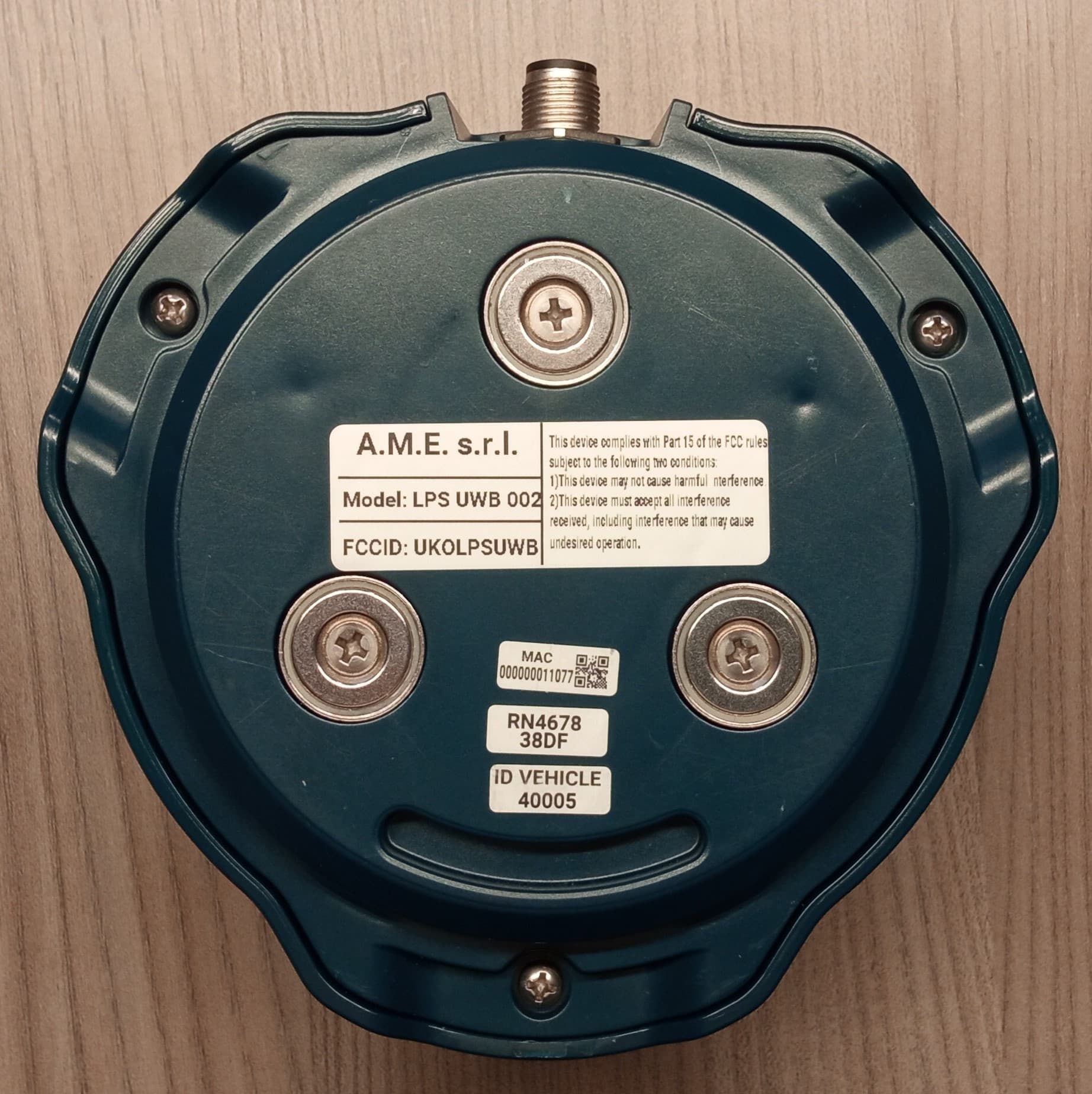
UKOLPSUWB-BT
Jul 23, 2023Sensor for detection and localization
Equipment Class
UWB - Ultra Wideband Transmitter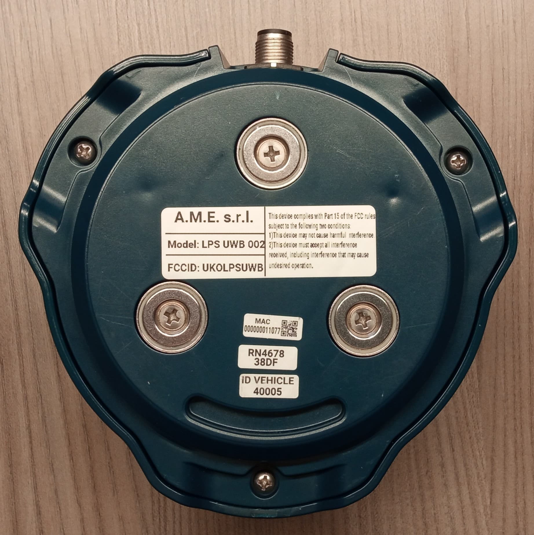
UKOLPSUWB
Feb 14, 2023Sensor for detection ad localization
Equipment Class
WBT - Wideband Transmitter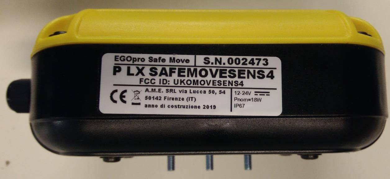
UKOMOVESENS4
Feb 03, 2020Sensor for EGOProSafe System
Equipment Class
DCD - Part 15 Low Power Transmitter Below 1705 kHz
UKOTAG3T
Feb 03, 2020Tag for EGOProSafe system
Equipment Class
DSC - Part 15 Security/Remote Control Transmitter