ULP-IQ6924LOW POWER TRANSMITTER (2400-2483.5 MHz)
Interactive Technologies, Inc.
Click to zoom
Application Details
- Equipment Class
- DXX - Part 15 Low Power Communication Device Transmitter
- Date of Grant
- Feb 04, 2013
- Application Purpose
- Original Equipment
- Date of Application
- Feb 04, 2013
- Equipment Note
- LOW POWER TRANSMITTER (2400-2483.5 MHz)
- Frequency Range
- 2405.00000000 - 2480.00000000
- Country
- United States
Documents & Files
Document Text
Text extracted from the exhibit documents filed with the FCC. Open a document above to read the original.
Users Manual
OEM MANUAL Refer to Freescale MC13213 operations manuals for complete descriptions. Microcontroller Features • Low voltage MCU with 40 MHz low power HCS08 CPU core • Up to 60K flash memory with block protection and security and 4K RAM — MC13211: 16KB Flash, 1KB RAM — MC13212: 32KB Flash, 2KB RAM — MC13213: 60KB Flash, 4KB RAM • Low power modes (Wait plus three Stop modes) • Dedicated serial peripheral interface (SPI) connected internally to 802.15.4 modem • One external 4-channel (5-channel internal) 16-bit timer/pulse width modulator (TPM) module and one external 1-channel (3-channel internal) 16-bit timer/pulse width modulator module, each with selectable input capture, output capture, and PWM capability. • 8-bit port keyboard interrupt (KBI) • 8-channel 8-10-bit ADC • Two independent serial communication interfaces (SCI) • Multiple clock source options — Internal clock generator (ICG) with 243 kHz oscillator that has +/-0.2% trimming resolution and +/-0.5% deviation across voltage. — Start-up oscillator of approximately 8 MHz — External crystal or resonator — External source from modem clock for very high accuracy source or system low-cost option • Inter-integrated circuit (IIC) interface with 100 kbps operation • In-circuit debug and flash programming available via on-chip background debug module (BDM) — Two comparator and 9 trigger modes — Eight deep FIFO for storing change-of-flow addresses and event-only data — Tag and force breakpoints — In-circuit debugging with single breakpoint • System protection features — Programmable low voltage interrupt (LVI) — Optional watchdog timer (COP) — Illegal opcode detection • Up to 32 MCU GPIO with programmable pull-ups RF Modem Features • Fully compliant 802.15.4 Standard transceiver supports 250 kbps O-QPSK data in 5.0 MHz channels and full spread-spectrum encode and decode • Operates on one of 16 selectable channels in the 2.4 GHz ISM band • -1 to 0 dBm nominal output power, programmable from -27 dBm to +3 dBm typical • Receive sensitivity of <-92 dBm (typical) at 1% PER, 20-byte packet, much better than the 802.15.4 Standard of -85 dBm • Integrated transmit/receive switch VOLTAGE INFORMATION: MODULE PINOUTS: Connector is 2 each 2x20 pins, 1mm x 1mm pitch MC13213 PORT BOARD CONNECTIONS: P1: 1 – D5 2 – D6 3 – D4 4 – D7 5 – GND 6 – B0 7 – GND 8 – B1 9 – VCC 10 – B2 11 – VCC 12 – B3 13 – VCC 14 – B4 15 – VCC 16 – B5 17 – GND 18 – B6 19 – GND 20 – B7 P2: 1 – A0 2 – A1 3 – E1 (RXD1) 4 – A2 5 – D0 (TXD1) 6 – A3 7 – C7 8 – A4 9 – C6 10 – A5 11 – C5 12 – A6 13 – C4 14 – A7 15 – C3 (SCL) 16 – BKGD 17 – C2 (SDA) 18 – RESET 19 –.C1 (RXD2) 20 – C0 (TXD2) BOARD LAYOUT: BOTTOM VIEW (TO BE MOUNTED FACE DOWN ON HEADER PINS): CHANNEL NUMBER TO FREQUENCY RANGE: * Channel number (0-15) * Channel frequencies : * 0 : 2.405GHz * 1 : 2.410GHz * 2 : 2.415GHz * 3 : 2.420GHz * 4 : 2.425GHz * 5 : 2.430GHz * 6 : 2.435GHz * 7 : 2.440GHz * 8 : 2.445GHz * 9 : 2.450GHz * 10: 2.455GHz * 11: 2.460GHz * 12: 2.465GHz * 13: 2.470GHz * 14: 2.475GHz * 15: 2.480GHz § 15.19 Labeling requirements (a) In addition to the requirements in part 2 of this chapter, a device subject to certification, or verification shall be labeled as follows: (3) All other devices shall bear the following statement in a conspicuous location on the device: This device complies with part 15 of the FCC Rules. Operation is subject to the following two conditions: (1) This device may not cause harmful interference, and (2) this device must accept any interference received, including interference that may cause undesired operation. § 15.21 Information to user The users manual or instruction manual for an intentional or unintentional radiator shall caution the user that changes or modifications not expressly approved by the party responsible for compliance could void the user's authority to operate the equipment. In cases where the manual is provided only in a form other than paper, such as on a computer disk or over the Internet, the information required by this section may be included in the manual in that alternative form, provided the user can reasonably be expected to have the capability to access information in that form.
Cover Letter(s)
15655 S. Mahaffie Street Olathe, KS 66062 Ja nuary 22, 2013 Federal Communications Commission Equipment Approval Services Post Offi ce Box 358315 Pittsburgh, Pennsylvania 15215-5315 To Whom It May Concern: Please be advised that Interactive Technologies, Inc. has authorized Scot Rogers of Rogers Labs, Inc. to act on behalf in all matters relating to application for equipment authorization, including the signing of all documents relating to these matters and submittals. All acts carried out by Rogers Labs, Inc. on our behalf shall have the same effects as our own. Rogers Labs, Inc. is authorized to receive and exc hange data between our company and the Commission. This Authorization is made pursuant to Paragraph 2.911 of FCC Rules CFR 47. This Authorization is in effect until otherwise notified in writing. Rob Dorrell President Interactive Technologies, Inc.
Cover Letter(s)
Page 1 of 2 January 30, 2013 Timco Engineering Inc. 849 NW State Road 45 Newberry, FL 32669 Applicant: Interactive Technologies, Inc. 15655 South Mahaffie Street Olathe, KS 66062 Re: Confidentiality for submittal information regarding FCC ID number ULP-IQ6924 PRODUCT: Low power Transmitters operated under paragraph 15.249. Dear Sirs: Interactive Technologies, Inc. requests that the material in the Schematics, Block Diagram, and Operational Description be withheld from public disclosure pursuant to Sections 0.457 and 0.459 of the Commission’s Rules following grant of the application. In support of this request, Interactive Technologies, Inc. submits the following information. CONFIDENTIAL FILES Conf BlkDia IQ6924.pdf Conf OpDes IQ6924.pdf Conf Schem IQ6924.pdf 1. Identification of the specific information for which confidential treatment is sought: The materials set forth in the Operational Description, block diagram, parts list, and Schematics, which are segregated, from the non-confidential exhibits of the application, are those for which confidentiality is sought. 2. Identification of the Commission proceeding in which the information was submitted or a description of the circumstances giving rise to the submission: The proceeding is that involving the application for equipment authorization (certification) under FCC ID No: ULP-IQ6924 3. Explanation of the degree to which the information is commercial or financial, or contains a trade secret or is privileged: This material includes a detailed theory of operation, circuit diagrams, and schematic. As such, this material is treated as highly confidential business information. ROGERS LABS, INC. 4405 West 259 th Terrace Louisburg, KS 66053 913 837-3214 Page 2 of 2 4. Explanation of the degree to which the information concerns a service that is subject to competition: The material for which confidentiality is sought is employed in the design and manufacture of this transmitting equipment that is offered on a highly competitive basis. Customers for this equipment have a variety of competing sources. 5. Explanation of how disclosure of the information could result in substantial competitive harm: Disclosure would, in effect, give away the fruits of the labors of Interactive Technologies, Inc.’s engineering personnel, who have designed the equipment and the manufacturing process. Disclosure would also offer competitors additional unwarranted insight into the state of the product development, thereby allowing competitors an advantage, not available to Interactive Technologies, Inc. 6. Identification of any measures taken by the submitting party to prevent unauthorized disclosure: The information for which confidential treatment is sought is kept confidential by Interactive Technologies, Inc. and not made available to third parties except pursuant to non-disclosure agreements. 7. Identification of whether the information is available to the public and the extent of any previous disclosure of the information to third parties: To the knowledge of those preparing this application, the information has not been disclosed publicly heretofore. While the general theory of operation of this equipment has been the subject of numerous disclosures in industry and standards groups as well as in rule making proceedings of the FCC, the protection sought is narrowly drawn and pertains to certain specific implementations of this radio technology. 8. Justification of the period during which the submitting party asserts that the material should not be available for public disclosure: This material should not be disclosed for at least 25 years. While improvements in design are made relatively frequently, disclosure of the design information would lead to insights into both design and manufacturing techniques that could have an adverse competitive effect for many years to come. As such, it is important that the design not be made available to unauthorized persons who might attempt to use knowledge of the design to compromise the applications for which the equipment will be employed. Should you require any further information, please contact the undersigned. Thank you for your consideration in this matter. Sincerely, Scot Rogers
Cover Letter(s)
February 1, 2013 Applicant: Interactive Technologies, Inc. 15655 South Mahaffie Street Olathe, KS 66062 Subject: Cover Letter requesting Modular Certification Equipment: FCC ID: ULP-IQ6924 FCC Rules: Part 2 and 15.249 (Single Modular Low Power Transmitter) Gentlemen: In accordance with Public Notice DA00-1407 regarding Part 15 unlicensed modular transmitter approval, the following information has been addressed. The transmitter module is a complete RF transmitter containing its own reference oscillator, antenna etc. The connections available on the module are for power and data interface. Below please find information, addressing each paragraph from DA00-1407, requested about the unit. 1.) The unit has shield effectively preventing coupling between the RF circuitry of the module and any wires or circuits in the device into which the module is installed. Photographs of the unit are included in an exhibit with the application. 2.) The unit incorporates a buffer stage on the inputs to limit over-modulation. 3.) The unit has power regulation incorporated in the circuitry to ensure continued compliance regardless of the design of the power supplying circuitry. 4.) The unit utilizes a unique antenna configuration embedded in the printed circuit board and complies with the antenna requirements. 5.) The module was tested while placed in the open and attached to a development interface board during testing. The module complies with part 15 emissions limits regardless of the device into which it is eventually installed. 6.) The module has the FCC ID number permanently affixed to the equipment and instruction offered addressing required information and placement on the exterior of enclosures in which the equipment is contained. 7.) The unit complies with CFR47 regulations as stated in the user manual. Adequate instructions are supplied with the unit to explain requirements. 8.) The unit complies with the RF exposure requirements as stated in 2.1091, 2.1093, and part 15. Should you require any further information, please contact the undersigned. Thank you for your consideration in this matter. Sincerely, Scot D. Rogers Rogers Labs, Inc. ROGERS LABS, INC. 4405 West 259 th Terrace Louisburg, KS 66053 Phone / Fax (913) 837-3214
Cover Letter(s)
January 30, 2013 Timco Engineering Inc. 849 NW State Road 45 Newberry, FL 32669 Applicant: Interactive Technologies, Inc. FCC ID: ULP-IQ6924 15655 South Mahaffie Street CORES number: 0015 49 1277 Olathe, KS 66062 FCC Rules: Parts 2 and 15.249 To Whom It May Concern: The form 731 and application have been electronically submitted and any attachments will be up loaded to your web site for use in obtaining a grant of certification. Confidentiality is requested as outlined below. Permanent Interactive Technologies, Inc. requests that the material in the Schematics, Block Diagram, and Operational Description be withheld from public disclosure pursuant to Sections 0.457 and 0.459 of the Commission’s Rules following grant of the application. A statement of confidentiality will be attached with the application at the time of submittal. Exhibit File Schematics Conf Schem IQ6924.pdf Block diagram Conf BlkDia IQ6924.pdf Operational Description Conf OpDes IQ6924.pdf Should you require any further information, please contact the undersigned. Thank you for your consideration in this matter. Sincerely, Scot Rogers Rogers Labs, Inc. Enclosures ROGERS LABS, INC. 4405 West 259 th Terrace Louisburg, KS 66053 Phone / Fax (913) 837-3214
External Photos
Rogers Labs, Inc. Interactive Technologies, Inc. 4405 West 259 th Terrace Model: IQ69-2.4 FCC ID: ULP-IQ6924 Louisburg, KS 66053 Test #: 130103 SN: ENG1 Phone/Fax: (913) 837-3214 Test to: FCC CFR 47 15.249, RSS 210 Date: January 22, 2013 Revision 1 File: ExtPho IQ6924 Page 1 of 1 External Photos Rogers Labs, Inc. Interactive Technologies, Inc. 4405 West 259 th Terrace Model: IQ69-2.4 FCC ID: ULP-IQ6924 Louisburg, KS 66053 Test #: 130103 SN: ENG1 Phone/Fax: (913) 837-3214 Test to: FCC CFR 47 15.249, RSS 210 Date: January 22, 2013 Revision 1 File: ExtPho IQ6924 Page 2 of 1 EUT placed on development board Rogers Labs, Inc. Interactive Technologies, Inc. 4405 West 259 th Terrace Model: IQ69-2.4 FCC ID: ULP-IQ6924 Louisburg, KS 66053 Test #: 130103 SN: ENG1 Phone/Fax: (913) 837-3214 Test to: FCC CFR 47 15.249, RSS 210 Date: January 22, 2013 Revision 1 File: ExtPho IQ6924 Page 3 of 1 Support Development Board
ID Label/Location Info
Rogers Labs, Inc. Interactive Technologies, Inc. 4405 West 259 th Terrace Model: IQ69-2.4 FCC ID: ULP-IQ6924 Louisburg, KS 66053 Test #: 130103 SN: ENG1 Phone/Fax: (913) 837-3214 Test to: FCC CFR 47 15.249, RSS 210 Date: January 22, 2013 Revision 1 File: LabelSmpl IQ6924 Page 1 of 1 FCC ID label and location
Internal Photos
Rogers Labs, Inc. Interactive Technologies, Inc. 4405 West 259 th Terrace Model: IQ69-2.4 FCC ID: ULP-IQ6924 Louisburg, KS 66053 Test #: 130103 SN: ENG1 Phone/Fax: (913) 837-3214 Test to: FCC CFR 47 15.249, RSS 210 Date: February 1, 2013 Revision 1 File: IntPho IQ6924 Page 1 of 1 Internal Photographs
Test Report
NVLAP Lab Code 200087-0 Rogers Labs, Inc. Interactive Technologies, Inc. 4405 West 259 th Terrace Model: IQ69-2.4 FCC ID: ULP-IQ6924 Louisburg, KS 66053 Test #: 130103 SN: ENG1 Phone/Fax: (913) 837-3214 Test to: FCC CFR 47 15.249, RSS 210 Date: February 2, 2013 Revision 1 File: Interactive Tech IQ6924m TstRpt 130103 Page 1 of 28 Test Report for CFR47 15C FOR Interactive Technologies, Inc. 15655 South Mahaffie Street Olathe, KS 66062 Model: IQ69-2.4 Low Power Transmitter Module FCC ID: ULP-IQ6924 Test Report Number 130103 Authorized Signatory: Scot D. Rogers NVLAP Lab Code 200087-0 Rogers Labs, Inc. Interactive Technologies, Inc. 4405 West 259 th Terrace Model: IQ69-2.4 FCC ID: ULP-IQ6924 Louisburg, KS 66053 Test #: 130103 SN: ENG1 Phone/Fax: (913) 837-3214 Test to: FCC CFR 47 15.249, RSS 210 Date: February 2, 2013 Revision 1 File: Interactive Tech IQ6924m TstRpt 130103 Page 2 of 28 Test Report for Application of Certification For Interactive Technologies, Inc. 15655 South Mahaffie Street Olathe, KS 66062 Phone: (913) 254-0887 111 Mr. Rob Dorrell President Model: IQ69-2.4 Low Power Transmitter Frequency Range: 2,405-2,480 MHz FCC ID: ULP-IQ6924 Test Report Number: 130103 Test Date: January 3, 2013 Authorized Signatory: Scot D. Rogers Rogers Labs, Inc. 4405 West 259th Terrace Louisburg, KS 66053 Telephone/Facsimile: (913) 837-3214 This report shall not be reproduced except in full, without the written approval of the laboratory. This report must not be used by the client to claim product endorsement by NVLAP, NIST, or any agency of the Federal Government. ROGERS LABS, INC. 4405 West 259 th Terrace Louisburg, KS 66053 Phone / Fax (913) 837-3214 NVLAP Lab Code 200087-0 Rogers Labs, Inc. Interactive Technologies, Inc. 4405 West 259 th Terrace Model: IQ69-2.4 FCC ID: ULP-IQ6924 Louisburg, KS 66053 Test #: 130103 SN: ENG1 Phone/Fax: (913) 837-3214 Test to: FCC CFR 47 15.249, RSS 210 Date: February 2, 2013 Revision 1 File: Interactive Tech IQ6924m TstRpt 130103 Page 3 of 28 Table of Contents TABLE OF CONTENTS .................................................................................................... 3 REVISIONS ....................................................................................................................... 4 FORWARD ....................................................................................................................... 5 OPINION / INTERPRETATION OF RESULTS ................................................................. 5 ENVIRONMENTAL CONDITIONS.................................................................................... 5 STATEMENT OF MODIFICATIONS AND DEVIATIONS ................................................. 5 APPLICATION FOR CERTIFICATION ............................................................................. 6 EQUIPMENT TESTED SETUP, FUNCTION AND CONFIGURATIONS .......................... 7 Equipment Function and Test Setup ....................................................................................................................... 7 Limited Modular Compliance Statements .............................................................................................................. 7 EUT Configuration ................................................................................................................................................... 7 LIST OF TEST EQUIPMENT ............................................................................................ 8 UNITS OF MEASUREMENTS .......................................................................................... 9 TEST SITE LOCATIONS .................................................................................................. 9 APPLICABLE STANDARDS & TEST PROCEDURES .................................................... 9 AC Line Conducted Emission Test Procedure ....................................................................................................... 10 Diagram 1 Test arrangement for Conducted emissions .......................................................................................... 10 Radiated Emission Test Procedure ......................................................................................................................... 11 Diagram 2 Test arrangement for radiated emissions of tabletop equipment .......................................................... 12 Diagram 3 Test arrangement for radiated emissions tested on Open Area Test Site (OATS) ............................... 13 INTENTIONAL RADIATORS ............................................................................................ 13 Antenna Requirements ............................................................................................................................................. 13 Restricted Bands of Operation ................................................................................................................................ 14 Table 1 Radiated Emissions in Restricted Bands Data (worst-case) .................................................................... 14 Summary of Results for Radiated Emissions in Restricted Bands ....................................................................... 15 General Radiated EMI Testing Procedure ............................................................................................................. 15 Table 2 General Radiated Emissions from EUT Data (Highest Emissions) ........................................................ 16 NVLAP Lab Code 200087-0 Rogers Labs, Inc. Interactive Technologies, Inc. 4405 West 259 th Terrace Model: IQ69-2.4 FCC ID: ULP-IQ6924 Louisburg, KS 66053 Test #: 130103 SN: ENG1 Phone/Fax: (913) 837-3214 Test to: FCC CFR 47 15.249, RSS 210 Date: February 2, 2013 Revision 1 File: Interactive Tech IQ6924m TstRpt 130103 Page 4 of 28 Summary of Results for General Radiated Emissions .....................................................................................…
Text truncated - open the document above for the full version.
Test Setup Photos
Rogers Labs, Inc. Interactive Technologies, Inc. 4405 West 259 th Terrace Model: IQ69-2.4 FCC ID: ULP-IQ6924 Louisburg, KS 66053 Test #: 130103 SN: ENG1 Phone/Fax: (913) 837-3214 Test to: FCC CFR 47 15.249, RSS 210 Date: January 22, 2013 Revision 1 File: TSup IQ6924 Page 1 of 1 Test Setup Photographs
Contact Information
Applicant
Rob Dorrell(President)
Test Firm
Rogers Labs, Inc.Scot Rogers
Technical Specifications
| # | Rule Parts | Frequency Range | Power Output |
|---|---|---|---|
| 1 | 15C | 2.40 GHz - 2.48 GHz | - |
Other Applications from Interactive Technologies, Inc.

ULP-24IQ58
Jul 20, 20158 Button Remote
Equipment Class
DTS - Digital Transmission System
ULPIQ58-433
Apr 07, 2008PERIODIC OPERATION CONTROL SIGNAL TRANSMITTER
Equipment Class
DSC - Part 15 Security/Remote Control Transmitter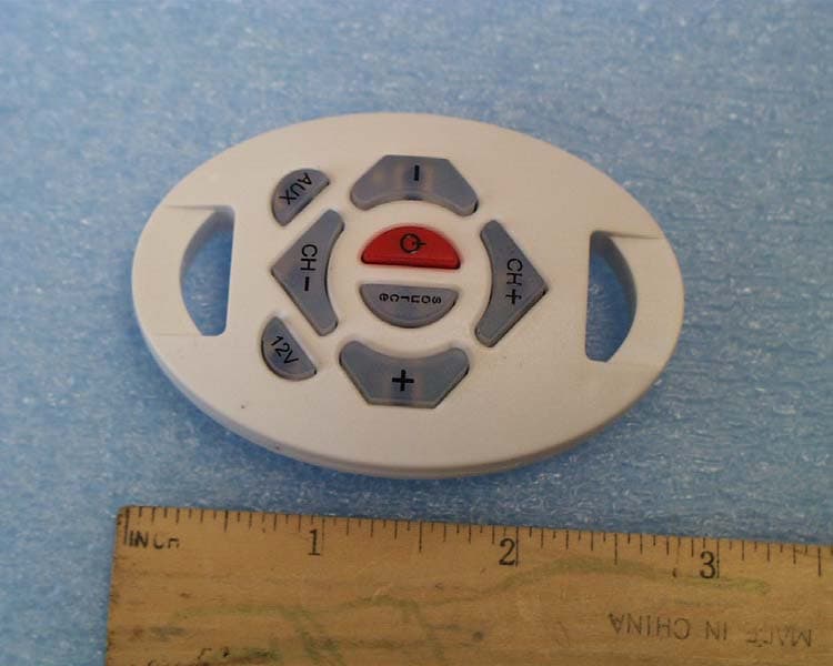
ULPIQ58
Dec 06, 2006PERIODIC OPERATION CONTROL SIGNAL TRANSMITTER
Equipment Class
DSC - Part 15 Security/Remote Control Transmitter