UNWFWT-200FIXED WIRELESS PHONE
Greenfield Invest & Trade Inc.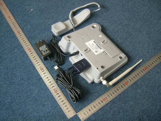
Click to zoom
Application Details
- Equipment Class
- PCB - PCS Licensed Transmitter
- Date of Grant
- Nov 01, 2006
- Application Purpose
- Original Equipment
- Date of Application
- Oct 30, 2006
- Equipment Note
- FIXED WIRELESS PHONE
- Frequency Range
- 1851.25000000 - 1908.75000000
- Country
- Panama
Documents & Files
Document Text
Text extracted from the exhibit documents filed with the FCC. Open a document above to read the original.
Users Manual
CDMA Cellular Wireless Phone 1 Read this manual carefully before operating the instrument. Ver 1.0 User Guide 2 CONTENTS INTRODUCTION...........................................................................4 IMPORTANT INFORMATION........................................................5 DO’S & DON’TS............................................................................6 VIEWS...........................................................................................8 PHONE FUNCTIONS AND FEATURES.......................................9 INSTALLATION...........................................................................18 BASIC OPERATIONS.................................................................20 MENU FUNCTION.......................................................................25 MENU STRUCTURE...............................................................25 MENU DESCRIPTION............................................................29 DATA SERVICES.........................................................................43 3 APPENDIX A: TEXT INPIDEUT METHOD GU...........................51 APPENDIX B: PRODUCT SPECIFICATION...............................51 APPENDIX C: CHARGER SPECIFICATION..............................52 APPENDIX D: PACKING LIST....................................................52 INTR Congratulations on your purchase of the CDMA Cellular Wireless Phone (Herei the las (CDMA). The CDMA technology has many advanced features and provides an excelle The P • Choice of 15 ring sounds, Power On/Off • Two Way SMS, Voice Mail and caller ID • Large ergonomically designed Keyboard • Long Battery stand-by and talk time • Menu driven interface for easy operation and configuration • Last Number Redial • Adjustable ring and voice volume • AC Power Supply • Indoor and Outdoor Antenna • Speaker Phone • CDMA technology allows privacy of the call • Optional accessories available for greater convenience and enhanced functionality • Easy Service and Repair • Subscriber Call Charge Meter ODUCTION nafter referred to as Phone). The Phone has been designed to operate with test digital communication technology, Code Division Multiple Acces nt voice quality hone has advanced features as follows: • Large, easy to read, backlit LCD with status icons 4 IMPORTANT INFORMATION e to the phone. Check the contents of the box as per the acking list and report any discrepancies immediately to the store from where This user guide provides information on the use and operation of your phone. Kindly read all the information contained in this user guide carefully prior to using the phone. This will help you in getting the best performance and shall prevent any unintended damag p phone has been purchased. 5 DO’S & DON’TS • Do not clean the phone while in operation. Before attempting to clean the Phone, turn the Phone off, disconnect the external power adapter and take out the battery or disconnect the external power supply if used. Before moving the Phone, disconnect the external power adapter or power supply in use. Use a Damp cloth for cleaning. Do not use liquid or aerosol cleaners. • Do not hold the antenna. This may affect call quality and cause telephone to operate at unintended power levels. • Keep the antenna free from obstructions and position the antenna straight up. This will ensure best call quality. • Do not use a damaged antenna. Have this replaced through a qualified technician. Use only antenna approved by the manufacturer. Unapproved antenna may impair the call quality as well as cause damage to the phone. • Only use the battery and the power adapter or the Power Supply provided with the Instrument. The instrument might get damaged if any other accessories are used. This will also void the warranty. • It is highly recommended to charge the battery before initial use. The battery might have been discharged during storage and delivery. • Do not use with car battery. It may lead to electric shock or breakdown. • Do not throw battery. Batteries are not to be disposed off by putting them in fire. It may explode or catch fire. • Do not attempt to change the security codes or components. User is responsible for any consequences arising out of such attempt. • Avoid Shock or Impact. Rough handling can cause damage to the body as well as internal circuits. • Do not paint. • During lightening, do not touch power plug or phone line. This can cause electric shock or death. Do not touch the external antenna. 6 • Your phone is to w connecting. ork with 90-300 V AC. Check the voltage before • Do not plug many power cords in the outlet. • • working for any reason, do not attempt to repair the • • e Instrument in a dry place and do not expose to moisture. • ron turned • Do not touch the plug with wet hands. Always grasp and pull the plug, not the cord. Do not put heavy things on the power cord or bend it too much. Do not take out the backup battery without the guide of qualified service personnel. If the unit is not Instrument. The Instrument should be serviced by qualified service personnel only. • Place the Instrument and the power supply in a properly ventilated place. Do not place the Instrument near high temperature objects, under direct sunlight, near source of water, near fire or near inflammable and explosive materials. Do not place any articles over the instrument. Place th • Place the Instrument away from other electronic devices like TV and Radio to avoid interference. For a better reception, do not place the Instrument in a building with i or metal roof. Hospitals or health care facilities may be using equipment sensitive to Radio Frequencies. Please ensure that your phone is off while in the vicinity of such facilities. • Do not use the unit in designated “No Cellular Phone Use” area 7 VIEWS Pho : Note: act l ne (1) The Base Instrument, (2) Handset, (3) Handset Cord, (4) Indoor Antenna The legends on picture shown may not be same as per the ua model. 8 PHONE FUNCTIONS AND FEATURES Your …
Text truncated - open the document above for the full version.
Cover Letter(s)
Date: 26 Oct, 2006 To: Federal Communications Commission, Authorization & Evaluation Division, 7435 Oakland Mills Road, Columbia, MD 21046 Re: GREENFIELD INVEST & TRADE INC. FCC ID: UNWFWT-200 FCC Part 15&24 Certification Confidentiality Request Gentlemen: This letter is to comply with 47 CFR 0.457 and 0.459 pertaining to confidentiality material. GREENFIELD INVEST & TRADE INC. requests that the following documents regarding this submission for FCC ID: UNWFWT-200 be kept confidential: Exhibit Type File Name 1. Block Diagram FWP Block diagram.pdf 2. Schematics FWP Circuit Diagram.pdf 3. Operational Description Circuit description.pdf/Specification of FWP.pdf 4. Part list/Tune-Up-Procedure BOM.pdf/Tune Up Info.pdf Those documents contain detailed system and equipment description and related information about the product which GREENFIELD INVEST & TRADE INC. considers to be confidential proprietary, a custom design and, otherwise, not releasable to the general public. Since this design is a basis form which future technological products will evolve, GREENFIELD INVEST & TRADE INC. considers this information would be of benefit to its competitors, and that the disclosure of the information in these documents would give competitors an unfair advantage in the market. Raul Castro Director GREENFIELD INVEST & TRADE INC.
External Photos
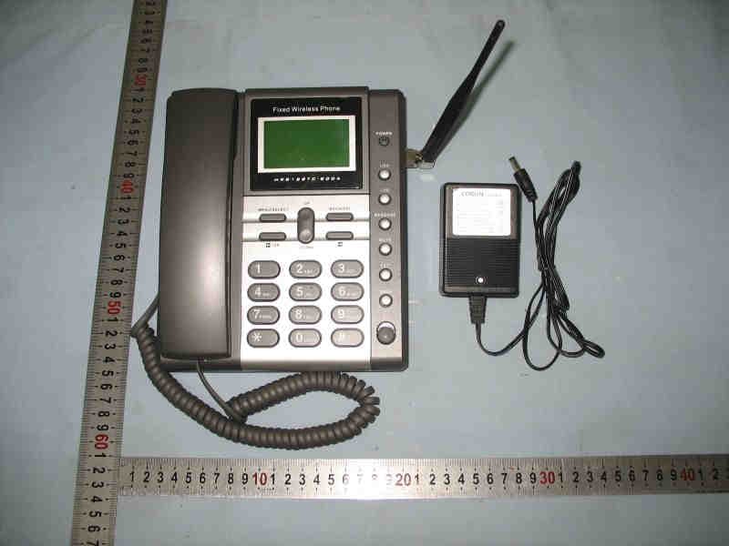
External Photos 1. Front View of EUT 2. Inside View of EUT 3. Back View of EUT
ID Label/Location Info
Label Label Location
Internal Photos
Internal Photos
RF Exposure Info
RF exposure requirements Device Type: INDIGO FWT-200 Fixed, General Population/Uncontrolled exposure Dear Sir, The transmitter is using indoor antennas that operate at 20 cm or from nearby persons. The maximum permitted level is calculated using the general equation: S=P*G/4πR 2 Here P=617mW G=3 R=20cm π= 3.1416 Solving for S, the power density at 20 cm is 0.368 mW/cm 2 . So the 1 mW/cm2 limit is kept. Please contact us if you have any additional questions. Best Regards Morlab Wu Xuewen Certification Manager
Test Report
Report No. FCC06-8079 Page 2 of 56 Table of Contents 1 Test Report Certification ...............................................................................................................5 2 General Information ......................................................................................................................6 2.1 Description of EUT ...............................................................................................................6 2.2 Objective ...............................................................................................................................7 2.3 Test Standards and Results ....................................................................................................7 2.4 List of Equipments Used .......................................................................................................8 2.5 Test Facility ...........................................................................................................................8 2.6 Environmental conditions .....................................................................................................8 3 Conducted Emission Test ..............................................................................................................9 3.1 Limits of Conducted Emission..............................................................................................9 3.2 Test Procedure .......................................................................................................................9 3.3 Test Setup ............................................................................................................................10 3.4 EUT Setup and Operating Conditions.................................................................................10 4 Radiated Emission Test ...............................................................................................................15 4.1 Limits of Radiated Emission ...............................................................................................15 4.2 Test Procedure .....................................................................................................................15 4.3 Test Setup ............................................................................................................................16 4.4 EUT Setup and Operating Conditions.................................................................................16 4.5 Test Results .........................................................................................................................16 5 Frequencies .................................................................................................................................20 5.1 Frequency Blocks Available for Broadband PCS ...............................................................20 5.2 Test Procedure .....................................................................................................................20 5.3 Test Setup ............................................................................................................................21 5.4 EUT Setup and Operating Conditions.................................................................................21 5.6 Test Results .........................................................................................................................21 6 Conducted RF Output Power Test...............................................................................................23 6.1 RF Power Output Test Requirement ...................................................................................23 6.2 Test Procedure .....................................................................................................................23 Report No. FCC06-8079 Page 3 of 56 6.3 Test Setup ............................................................................................................................23 6.4 EUT Setup and Operating Conditions.................................................................................23 6.5 Test Results .........................................................................................................................24 7 Occupied Bandwidth Test ...........................................................................................................26 7.1 Definition ............................................................................................................................26 7.2 Test Procedure .....................................................................................................................26 7.3 Test Setup ............................................................................................................................26 7.4 EUT Setup and Operating Conditions.................................................................................26 7.5 Test Results .........................................................................................................................27 8 Conducted Spurious Emission Test.............................................................................................29 8.1 Limits of Conducted Spurious Emission.............................................................................29 8.2 Test Procedure .....................................................................................................................29 8.3 Test Setup ............................................................................................................................29 8.4 EUT Setup and Operating Conditions.................................................................................29 8.5 Test Results .........................................................................................................................30 9 Transmitter Radiated Power (EIRP/ERP) Test...............................................................…
Text truncated - open the document above for the full version.
Test Setup Photos
Test Setup Photos 1. CE 2. CSE 3. RE 4. RSE
Contact Information
Applicant
Raul Castro(Mr)
Test Firm
ShenZhen Electronic Product Quality Testing CenterXingsun Lin
Technical Specifications
| # | Rule Parts | Frequency Range | Power Output | Emission | Tolerance |
|---|---|---|---|---|---|
| 1 | 24E | 1.85 GHz - 1.91 GHz | 617.00 mW | 1M25F9W | 0.1000000000 ppm |
Other Applications from Greenfield Invest & Trade Inc.
UNWTC800A
Oct 23, 2006Fixed Wireless Terminal
Equipment Class
PCB - PCS Licensed Transmitter