UNWTC800AFixed Wireless Terminal
Greenfield Invest & Trade Inc.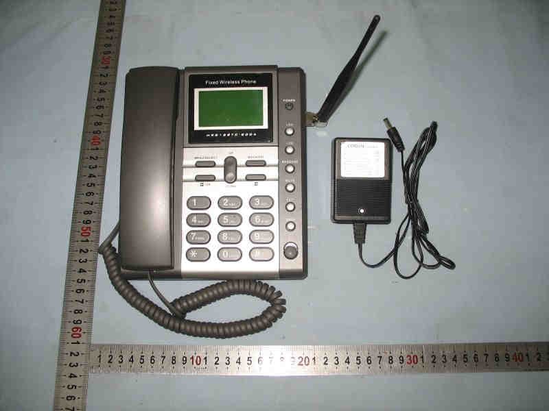
Click to zoom
Application Details
- Equipment Class
- PCB - PCS Licensed Transmitter
- Date of Grant
- Oct 23, 2006
- Application Purpose
- Original Equipment
- Date of Application
- Oct 23, 2006
- Equipment Note
- Fixed Wireless Terminal
- Frequency Range
- 1851.25000000 - 1908.75000000
- Country
- Panama
Documents & Files
Document Text
Text extracted from the exhibit documents filed with the FCC. Open a document above to read the original.
Users Manual
SILVER FWT-400 C D M A F I X E D W I R E L E S S T E R M I N A L Please read before use and save USER'S MANUAL 2 4.5.1 Horizontal Mode 4.5.2 Wall Mounting Mode Chapter 5 Basic Operations 5.1 Contacts 5.2 Messages 5.3 Call records 5.4 Tools 5.5 Settings 5.6 Additional function 5.7 Maintenance Chapter 6 troubleshooting Chapter 6 technical specification Chapter 7 Configuration 7.1 Computer Configuration 7.2 Configure FWP Chapter 8 FCC statement 8.1 FCC statement TABLE OF CONTENTS 1 Chapter 1 Precautions 1.1 Basic Cautions 1.2 Security Cautions 1.3 Installation Cautions 1.4 Maintenance Chapter 2 Introduction 2.1 Packing List 2.2 Product Features Chapter 3 Function Description 3.1 Display and Operating Elements 3.1.1 FWT Front View and Description 3.1.2 FWT Back View and Description 3.1.3 FWT Side View and Description 3.2 Display Screen Description 3.2.1 Standby State Chapter 4 Installation Description 4.1 External Power Adapter Installation 4.2 Spare Battery Detachment/Installation 4.3 Connecting the FWT to a PC 4.3.1 Connecting the FWT to a PC through a Serial Communication Cable 4. 4 Antenna and feeder 4.4.1 Indoor Omni Antenna 4.5 Mounting Mode TABLE OF CONTENTS 3 3 6 6 8 9 11 11 13 14 15 15 16 16 18 19 19 20 20 20 20 22 24 26 28 29 36 36 38 40 41 49 50 50 41 1) Before cleaning the FWT, please turn off the FWT, and then disconnect the external power adapter and take out the Battery. Before moving the FWT, please disconnect the external power adapter. 1.1 Basic Cautions To use the Fixed Wireless Terminal (hereinafter referred to as the FWT) accurately, efficiently and securely, you should notice the following cautions. CHAPTER 1 PRECAUTIONS 1.2 Security Cautions CHAPTER 1 PRECAUTIONS 2) When lightning, if you use the power adapter, please turn off the FWT and disconnect the power adapter from external power supply. If outdoor antenna is used, please turn off the FWT and do not touch the interface between FWT and antenna. 3) Do not open the chassis in normal condition. The device should be maintained by a qualified maintenance department. 4) Do select its self-contained complete battery and power adapter. Otherwise, the FWT may be damaged. 34 6) Without permission, users are not allowed to modify the architecture and security design of the FWT. Otherwise, users must bear any consequence resulted from the operation. 5) Disconnect the external power adapter and take out the spare battery when the FWT is not used for a long time. 1) Check fittings based on the packing list to make sure they are complete and undamaged. 2) Read this manual carefully before installing and using the FWT. 7) Battery If the battery fluid gets into the eyes, do not rub them. Wa- sh with clean water and seek medical assistance immedi- ately. If the battery fluid contacts skin or cloth, wash with clean water immediately to avoid irritation to the skin. Do not dispose of the battery in fire. Otherwise, the battery may ignite or explode. When installing the battery on your FWT, do not push the battery by force lest the battery fluid leak out or the battery crack. Do not connect two poles of the battery with metallic mate- rials such as cables. Do not disassemble the battery or solder the battery poles. Otherwise, fluid leakage, overheat, fire or explosion may result. If there is battery leakage, smoke, or strange smell, stop using the battery and keep it away from open flame to av- oid fire or explosion. Disconnect the power adapter and take out the spare bat- tery when FWT is not used for a long time. 1) Put the main unit and the power supply in a ventilated, shadowy and cool place. Never airproof the FWT or put some articles on it or place it. 2) Put it in a dry place and do not expose it to moisture. 1.3 Installation Cautions 3) A working FWT may affect other electronic devices, such as TV set and radio, so you are recommended to place it away from these devices. 4) Place the FWT in a place where it can receive network sig- nal well. Do not put the FWT in a building with an iron or metal roof. The distance between the FWT and other metal materials (such as metal brackets or metal doors and windows) should be greater than 25cm and the distance between FWT should be greater than 30cm. 1)Keep the FWT and its accessories away from children. 1.4 Maintenance CHAPTER 1 PRECAUTIONSCHAPTER 1 PRECAUTIONS Do select its self-contained complete battery and power adapter, otherwise, FWT may be spoiled. Dispose of used batteries according to the instructions. Dispose of the battery according to local laws or regulatio- ns. 8) Power adapter Use AC power as specified for the power adapter. Any violation of this rule may result in fire or malfunction of the power adapter. Do not short-circuit the power adapter. Short-circuiting the power adapter may cause fire or malfunction of the power adapter. Remove the dust on the power plug regularly. Do not use worn-out power cords. Otherwise, electric sho- ck, short-circuiting of the power adapter or fire may result. Do not put the power adapter near the container filled with liquid such as water. If the liquid comes into the power ad- apter, electrical leakage or other faults may result. If the liquid such as water comes into the power adapter accidentally remove the plug of the power adapter from the socket immediately. Disconnect the power adapter from the socket before cle- aning or maintaining it. Otherwise, electric shock or short- circuit of the battery or the power adapter may result. Ensure the plug of the power adapter is properly inserted into the power socket when charging the battery. Improper insertion may result in electric shock, fire or explosion. Do not place any heavy objects on the power cord of the power adapter. Do not damage, change, or pluck the power cord. 2) The FWT should be deployed in a clean and dry environm- ent. A temperature higher than 55or lower than-10maybe 5 6 damages the FWT. If the FWT is covered with dust, please cle- an it with clean fine cloth. Be sure …
Text truncated - open the document above for the full version.
External Photos
Page 1 of 3 Type Designation: SILVER FWT-400 Report Number: 17005270 001 Figure 1. Figure 2. Page 2 of 3 Type Designation: SILVER FWT-400 Report Number: 17005270 001 Figure 3. Figure 4. Page 3 of 3 Type Designation: SILVER FWT-400 Report Number: 17005270 001 Figure 5. Figure 6. END OF THIS PHOTODOC
ID Label/Location Info
Page 1 of 2 Type Designation: SILVER FWT-400 Report Number: 17005270 001 Figure 1. Figure 2. Page 2 of 2 Type Designation: SILVER FWT-400 Report Number: 17005270 001 Figure 3. END OF THIS PHOTODOC
Internal Photos
Page 1 of 7 Type Designation: SILVER FWT-400 Report Number: 17005270 001 Figure 1. Figure 2. Page 2 of 7 Type Designation: SILVER FWT-400 Report Number: 17005270 001 Figure 3. Figure 4. Page 3 of 7 Type Designation: SILVER FWT-400 Report Number: 17005270 001 Figure 5. Figure 6. Page 4 of 7 Type Designation: SILVER FWT-400 Report Number: 17005270 001 Figure 7. Figure 8. Page 5 of 7 Type Designation: SILVER FWT-400 Report Number: 17005270 001 Figure 9. Figure 10. Page 6 of 7 Type Designation: SILVER FWT-400 Report Number: 17005270 001 Figure 11. Figure 12. Page 7 of 7 Type Designation: SILVER FWT-400 Report Number: 17005270 001 Figure 13. Figure 14. END OF THIS PHOTODOC
RF Exposure Info
Page 1 of 2 Type Designation: SILVER FWT-400 Report Number: 17005270 001 Prediction of MPE limit at given distance 1. Introduction Equation from page 18 of OET Bulletin 65, Edition 97-01 Where: S = power density P = power input to the antenna G = power gain of the antenna in the direction of interest relative to an isotropic radiator R = distance to the center of radiation of the antenna 2. Limits for Maximum Permissible Exposure According to FCC Part 1.1307, systems operating under the provisions of this section shall be operated in a manner the ensures that the public is not exposed to radio frequency energy level in excess of the commission’s guidelines. According to FCC Part 1.1310 RF exposure is calculated. Limits for General Population/ Uncontrolled Exposure Page 2 of 2 Type Designation: SILVER FWT-400 Report Number: 17005270 001 3. Test result Maximum peak output power at antenna input terminal: 25.35 (dBm) Maximum peak output power at antenna input terminal: 342.77 (mW) Prediction distance: 20 (cm) Predication frequency: 1880.00 (MHz) Antenna Gain (typical): 3 (dBi) Power density at predication frequency at 20 cm: 0.204 (mW/cm 2 ) MPE limit for RF exposure at prediction frequency: 1.0 (mW/cm 2 ) 4. Conclusion Test result is passed.
Test Report
Produkte Products Prüfbericht - Nr.: Test Report No. 17005270 001 Seite 2 von 41 Page 2 of 41 TEST SUMMARY 5.1 EFFECTIVE RADIATED POWER OF TRANSMITTER RESULT: Passed 5.2 MODULATION CHARACTERISTICS RESULT: Passed 5.3 OCCUPIED BANDWIDTH RESULT: Passed 5.4 BAND EDGE RESULT: Passed 5.5 SPURIOUS EMISSION AT ANTENNA TERMINAL RESULT: Passed 5.6 FIELD STRENGTH OF SPURIOUS EMISSION RESULT: Passed 5.7 FREQUENCY STABILITY RESULT: Passed 5.8 CONDUCTED EMISSIONS RESULT: Passed 5.9 RADIATED EMISSIONS OF IDLE MODE RESULT: Passed Produkte Products Prüfbericht - Nr.: Test Report No. 17005270 001 Seite 3 von 41 Page 3 of 41 Contents 1. GENERAL REMARKS......................................................................................................... 5 1.1 COMPLEMENTARY MATERIALS.......................................................................................... 5 2. TEST SITES...................................................................................................................... 5 2.1 TEST FACILITIES............................................................................................................... 5 2.2 LIST OF TEST AND MEASUREMENT INSTRUMENTS............................................................... 6 2.3 TRACEABILITY.................................................................................................................. 7 2.4 CALIBRATION................................................................................................................... 7 2.5 MEASUREMENT UNCERTAINTY........................................................................................... 7 2.6 LOCATION OF ORIGINAL DATA........................................................................................... 7 2.7 STATUS OF FACILITY USED FOR TESTING........................................................................... 7 3. GENERAL PRODUCT INFORMATION.................................................................................... 8 3.1 PRODUCT FUNCTION AND INTENDED USE........................................................................... 8 3.2 RATINGS AND SYSTEM DETAILS........................................................................................ 8 3.3 INDEPENDENT OPERATION MODES.................................................................................... 9 3.4 NOISE GENERATING AND NOISE SUPPRESSING PARTS....................................................... 9 3.5 SUBMITTED DOCUMENTS.................................................................................................. 9 4. TEST SET-UP AND OPERATION MODES............................................................................ 10 4.1 PRINCIPLE OF CONFIGURATION SELECTION...................................................................... 10 4.2 TEST OPERATION AND TEST SOFTWARE.......................................................................... 10 4.3 SPECIAL ACCESSORIES AND AUXILIARY EQUIPMENT........................................................ 10 4.4 COUNTERMEASURES TO ACHIEVE EMC COMPLIANCE....................................................... 10 4.5 TEST SETUP DIAGRAM.................................................................................................... 11 5 . TEST RESULTS O F TR A N S M I T T E R...................................................................... 13 5.1 EFFECTIVE RADIATED POWER OF TRANSMITTER.............................................................. 13 5.2 MODULATION CHARACTERISTICS..................................................................................... 14 5.3 OCCUPIED BANDWIDTH................................................................................................... 16 5.4 BAND EDGE................................................................................................................... 19 5.5 SPURIOUS EMISSION AT ANTENNA TERMINAL................................................................... 21 5.6 FIELD STRENGTH OF SPURIOUS EMISSION......................................................................... 30 5.7 FREQUENCY STABILITY................................................................................................... 32 5.8 CONDUCTED EMISSIONS.................................................................................................. 34 5.9 RADIATED EMISSIONS OF IDLE MODE............................................................................... 36 Produkte Products Prüfbericht - Nr.: Test Report No. 17005270 001 Seite 4 von 41 Page 4 of 41 6. PHOTOGRAPHS OF THE TEST SET-UP.............................................................................. 38 7. LIST OF TABLES............................................................................................................. 41 8. LIST OF PHOTOGRAPHS.................................................................................................. 41 Produkte Products Prüfbericht - Nr.: Test Report No. 17005270 001 Seite 5 von 41 Page 5 of 41 1. General Remarks 1.1 Complementary Materials None 2. Test Sites 2.1 Test Facilities AUDIX Technology (Shenzhen) Co., Ltd. No. 6, Ke Feng Road, Block 52 Shenzhen Science & Industry Park Nantou, Shenzhen Guangdong P.R. China The tests at the test site have been conducted under the supervision of a TÜV engineer. Produkte Products Prüfbericht - Nr.: Test Report No. 17005270 001 Seite 6 von 41 Page 6 of 41 2.2 List of Test and Measurement Instruments Table 1: List of Test and Measurement Equipment Kind of Equipment Manufacturer Type S/N Calibrated until Conducted emissions Receiver R/S ESHS 20 8366001006 2007-05-14 LISN Anritsu KNW-407 8-1628-5 2007-05-14 Field strength of Spurious emissions and Radiated emissions and E.R.P Amplifier HP 8447D 2944A07794 2007-09-12 Amplifier HP 8449B 3008A00863 2007-05-14 Antenna EMCO 3115 9607-4877 2007-12-09 Spectrum analyzer Agilent E4407B MY41440292 2007-05-14 Modulation Characteristics Wireless Communication Agilent E5515C GB44300243 2007-05-15…
Text truncated - open the document above for the full version.
Test Setup Photos
Produkte Products Prüfbericht - Nr.: Test Report No. 17005270 001 Seite 38 von 41 Page 38 of 41 6. Photographs of the Test Set-Up Photograph 1: Set-up for Conducted Emissions Photograph 2: Set-up for Radiated Emissions of Idel Mode Produkte Products Prüfbericht - Nr.: Test Report No. 17005270 001 Seite 39 von 41 Page 39 of 41 Photograph 3: Set-up for Field strength of spurious emission below 1GHz Photograph 4: Set-up for Field strength of spurious emission above 1GHz Produkte Products Prüfbericht - Nr.: Test Report No. 17005270 001 Seite 40 von 41 Page 40 of 41 Photograph 5: Set-up for Frequency Stability
Contact Information
Applicant
Raul Castro(Mr)
Technical Specifications
| # | Rule Parts | Frequency Range | Power Output | Emission | Tolerance |
|---|---|---|---|---|---|
| 1 | 24E | 1.85 GHz - 1.91 GHz | 343.00 mW | 1M25F9W | 300.0000000000 Hz |
Other Applications from Greenfield Invest & Trade Inc.
UNWFWT-200
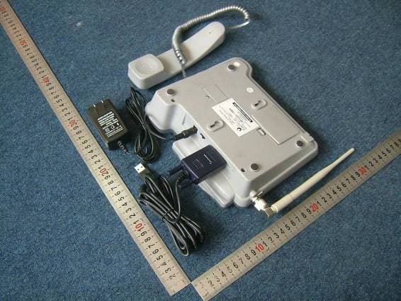
Nov 01, 2006FIXED WIRELESS PHONE
Equipment Class
PCB - PCS Licensed Transmitter