UR8100206VEHICLE BLIND SPOT DETECTION SYSTEM
Valeo Raytheon Systems, Inc.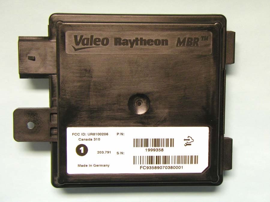
Click to zoom
Application Details
- Equipment Class
- DXX - Part 15 Low Power Communication Device Transmitter
- Date of Grant
- Feb 15, 2007
- Application Purpose
- Original Equipment
- Date of Application
- Feb 15, 2007
- Equipment Note
- VEHICLE BLIND SPOT DETECTION SYSTEM
- Frequency Range
- 24055.00000000 - 24239.00000000
- Company
- Valeo Raytheon Systems, Inc.
- Country
- United States
Documents & Files
Document Text
Text extracted from the exhibit documents filed with the FCC. Open a document above to read the original.
External Photos
External Photos: Blind Spot Detection System Front: Back:
ID Label/Location Info
1 Label Layout Identification num ber and bar code : CC component identifier PPPP part number S supplier code YYDDD date code NNNN unit number on that date Wemding Poka Yoke symbol: Service Programming Symbol Regulatory markings Part Number and barcode FCC ID: UR8100206Canada 310 1 Made in Germany P/N : 1999358 CCPPPPSYYDDDNNNN S/N: 203.791 6.4mm minimum “quiet area” before and after each bar code 2 Label Size 3 Label Placement FCC ID: UR8100206Canada 310 1 Made in Germany P/N : 1999358 CCPPPPSYYDDDNNNN S/N: 203.791 4 Picture of Unit with Label
Test Report
Compliance Worldwide, Inc. - 357 Main Street - Sandown, NH 03873 (603) 887 3903 Fax 887 6445 http://www.complianceworldwide.com COMPLIANCE WORLDWIDE INC. TEST REPORT 118-07R1 In Accordance with the Requirements of Industry Canada RSS 310, Issue 6 Federal Communications Commission CFR Title 47 Part 15.249 Subpart C Radio Communication Devices Intentional Radiators Issued to Valeo Raytheon Systems, Inc. 46 River Road Hudson, NH 03051-5227 Tel: (603) 578-8000 for Blind-Spot Detection Sensor FCC: ID UR8100206 Report Issued on February 13, 2007 This test report shall not be reproduced, except in full, without written permission from Compliance Worldwide, Inc. Test Number: 118-07R1 Issue Date: 2/13/2007 Page 2 of 18 Compliance Worldwide, Inc. - 357 Main Street - Sandown, NH 03873 (603) 887 3903 Fax 887 6445 http://www.cw-inc.com Table of Contents 1. Scope .................................................................................................................................. 3 2. Product Details.................................................................................................................... 3 2.1. Manufacturer ..............................................................................................................3 2.2. Model Number............................................................................................................ 3 2.3. Serial Number ............................................................................................................ 3 2.4. Description ................................................................................................................. 3 2.5. Power Source............................................................................................................. 3 2.6. EMC Modifications ..................................................................................................... 3 3. Product Configuration ......................................................................................................... 3 3.1. Operational Characteristics & Software ..................................................................... 3 3.2. Block Diagram ............................................................................................................ 4 4. Measurements Parameters................................................................................................. 4 4.1. Measurement Equipment Used to Perform Test ........................................................ 4 4.2. Measurement & Equipment Setup ............................................................................. 5 4.3. Measurement Procedure............................................................................................ 5 5. Measurement Summary...................................................................................................... 6 6. Measurement Data.............................................................................................................. 7 6.1. Radiated Field Strength of Fundamental ................................................................... 7 6.2. Radiated Field Strength of Harmonics ....................................................................... 8 6.3 Occupied Bandwidth ................................................................................................... 9 6.4 99% Bandwidth ......................................................................................................... 11 6.5. Band Edge Measurements....................................................................................... 13 6.6. Spurious Radiated Emissions, 30 MHz to EUT 10 th Harmonic ................................ 14 6.7. Determination of Averaging Factor .......................................................................... 17 7. Test Site Description ......................................................................................................... 18 Test Number: 118-07R1 Issue Date: 2/13/2007 Page 3 of 18 Compliance Worldwide, Inc. - 357 Main Street - Sandown, NH 03873 (603) 887 3903 Fax 887 6445 http://www.cw-inc.com 1. Scope This test report certifies that the Valeo Raytheon Systems, Inc. Blind-Spot Detection Sensor, as tested, meets the RSS 310 Rules and FCC Part 15.249, requirements. The scope of this test report is limited to the test sample provided by the client, only in as much as that sample represents other production units. If any significant changes are made to the unit, the changes shall be evaluated and a retest may be required. This report replaces 118-07 to add the determination of averaging factor. 2. Product Details 2.1. Manufacturer: Valeo Raytheon Systems, Inc. 2.2. Model Number: Blind-Spot Detection System 2.3. Serial Number: FC93409063200110 2.4. Description: The Blind-Spot Detection system utilizes multi beam radar sensors located out of sight behind the bumper fascia. These sensors monitor the adjacent lanes of traffic on the left and right sides of the vehicle and alert the driver to the presence of objects of interest, such as cars, trucks and motorcycles, in the driver's blind spots. 2.5. Power Source: 12 Volt DC (Automobile) 2.6. EMC Modifications: Snubber filters on PC board Vias 3. Product Configuration 3.1. Operational Characteristics & Software The Multi Beam Radar (MBR) is a frequency modulated continuous wave (FMCW) radar sensor module operating in the 24.0–24.25GHz band per FCC part 15, section 15.249. In order to ensure that the unit remains within the band limitations of 15.249, it undergoes a five point frequency calibration process every 256 milliseconds when it is operational. The unit is never operated without the frequency calibration process running when installed in a vehicle. In order to satisfy test requirements, a special test feature has been incorporated so that the frequency sweep can be stopped at the low, mid and upper points of the band. This is accomplished by putting the Voltage Controlled …
Text truncated - open the document above for the full version.
Test Setup Photos
Test Set Up photos: Blind Spot Detection System Radiated Front: Radiated Back:
Contact Information
Applicant
Kenneth Booth(Electrical Engineer)
Test Firm
Compliance Worldwide, Inc.Larry Stillings
Technical Specifications
| # | Rule Parts | Frequency Range | Power Output |
|---|---|---|---|
| 1 | 15C | 24.05 GHz - 24.24 GHz | - |
Other Applications from Valeo Raytheon Systems, Inc.
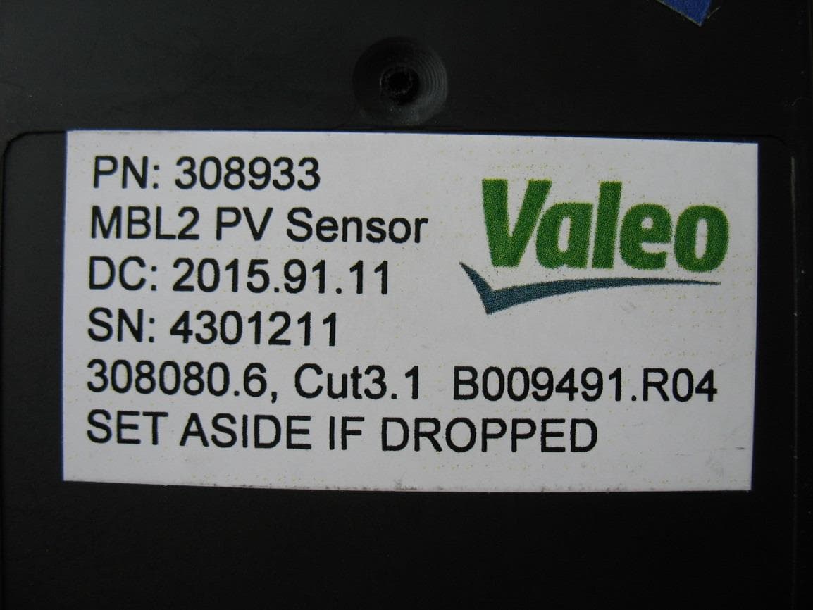
UR8307735
Aug 02, 201524 GHz distance radar
Equipment Class
DXX - Part 15 Low Power Communication Device Transmitter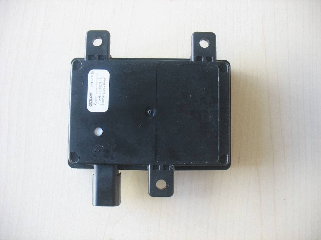
UR8303919
Aug 07, 201224GHz Automotive Radar
Equipment Class
DXX - Part 15 Low Power Communication Device Transmitter