URK-ASN900IP based Broadband Wireless Access System
Airspan Networks Finland Oy
Click to zoom
Application Details
- Equipment Class
- DTS - Digital Transmission System
- Date of Grant
- Mar 18, 2012
- Application Purpose
- Original Equipment
- Date of Application
- Mar 18, 2012
- Equipment Note
- IP based Broadband Wireless Access System
- Frequency Range
- 5745.00000000 - 5825.00000000
- Company
- Airspan Networks Finland Oy
- Country
- Finland
Documents & Files
Document Text
Text extracted from the exhibit documents filed with the FCC. Open a document above to read the original.
Users Manual
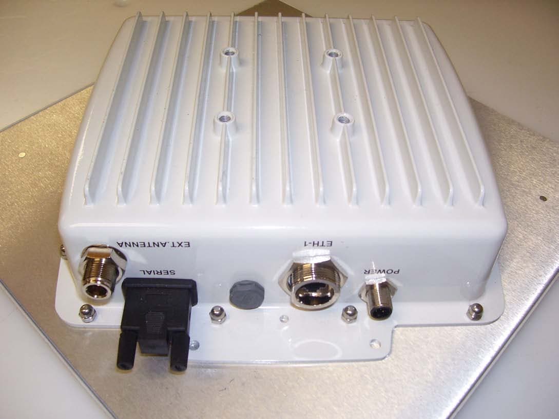
FlexNET IEEE 802.11 A/B/G Wireless Broadband Wi-Fi System 605-0001-802 Rev A FlexNET Access Products FlexNET ASN-900P: Dual RF, 5 GHz Integrated Antenna, PoE User’s Guide The Innovation Behind Broadband Wireless Connecting the World 1 PREFACE Thank you for purchasing Airspan‘s FlexNET ASN-820P/900P Base Station (hereafter referred to as FlexNET) device. The FlexNET devices are a part of Airspan‘s AS.NET product family. This section discusses the purpose, audience, conventions, and customer support of this guide. Purpose This Web-based Wi-Fi management User‘s Guide provides step-by-step instructions for configuring and managing your ASN BS using a standard Web browser. Targeted Audience This guide is intended for the end user. Conventions This guide uses the following typographical conventions: Convention Meaning Example Bold Command, icon, button, and field Click the Next button. ―To‖ in bold face and at the beginning of a sentence Introduces a numbered procedure To download a SW file: 1. ... Note that provides useful information -- Warning that provides information that can prevent and avoid bodily or mechanical harm -- 2 SAFETY INSTRUCTIONS Note: Traduction française dedans Appendix K This document must be reviewed for familiarization with the product and instructions before operation. Verify that an un-interruptible safety earth ground exists from main power source and the ground circuitry of the product. Verify that correct AC power source is available for the AC power adapter to produce 56 VDC for the product. Disconnect the product from operating power before cleaning. Warning! A professional installer must install the AC power adapter, base station and antennas. You are cautioned that changes or modifications not expressly approved by the part responsible for compliance could void the user‘s authority to operate the equipment. (FCC 15.21) Note on electromagnetic emissions This device complies with part 15 of the Federal Communications Commission (FCC) rules. Operation is subjected to the following conditions: This device may not cause harmful interference. This device must accept any interference received including interference that cause undesired operation Warning! Electromagnetic radiation. Please keep this product and related antennas at a distance 20 cm from human body when operational Regulatory notice The specifications and parameters of the device described in this document are subject to change without notice. For American regulatory information, see www.fcc.gov. For Canadian regulatory information, see www.ic.gc.ca. This equipment generates, uses and radiates energy on radio frequencies and, if not installed and used in accordance with this guide, may cause harmful interference to radio communications. However, there is no guarantee that interference will not occur in a particular installation. If this equipment does cause harmful interference to radio or television reception, which can be determined by turning the equipment off and on, the user is encouraged to correct the interference by one or more of the following methods: reorient or relocate the receiving antenna move the equipment and receive farther apart connect equipment to an outlet on a circuit different from that to which the receiver is connected The FlexNET product is only allowed to be used with Airspan antennas and accessories (PSU-4 power supply) and power dividers. In USA and Canada maximum allowed transmit power levels and channel frequencies are shown in Appendix F. 3 INTRODUCTION This guide contains information on how to operate and manage the FlexNET products. Package contents The FlexNET package contains the following items: ASN-820P or ASN-900P product Mounting kit with down tilt possibility Two weather proof RJ-45 connector kits (MOB00210) Indoor power supply unit PSU-4 Factory default tool Mounting instruction Documentation CD-ROM Physical interfaces and description Key features of the FlexNET product are: Two external antenna connectors Two 10/100 Base TX Ethernet ports Operation indication LED RS-232 interface for local management Antenna The ASN-900P is delivered with an integrated 5.150-5.875 GHz 23dBi planar antenna. Aluminium enclosure The base station unit uses an aluminium enclosure that supports both outdoor operating environments and an industrial temperature operating range (-40...+55 C). Connectors All connectors are located on the bottom of the housing. The FlexNET product has two external antenna connectors and two Ethernet connectors. Indication LED Female N-type connectors for external antennas Female N-type connectors for external antennas Ethernet connectors Power connector Power connector VENT RS-232 (DB-9) ANTENNA Figure 1 The FlexNET product bottom view LED indicator The LED indicator is also located on the bottom of the housing. The operation of the LED indicator is as follows: Reboot: flashing blue once per second Committing configuration and initializing the radios: flashing blue twice per second Factory reset: solid red when erasing the configuration Upgrade software: the colour of the LED varies between red and blue Vent The vent can be found on the bottom of the housing as well. The vent equalizes pressure and lets moisture out of the chassis. It does not need your attention 4 Serial RS-232 interface The serial RS-232 interface can be used for local management, as well as resetting the unit to factory defaults. The serial RS-232 connector on the unit is standard DB9 female connector. See Appendix K Information for RS-232 interface for more details. Note1: Unplug the serial cable from the PC when powering up the ASN Link unit. With some PCs the serial cable connection can cause factory reset during power up Note2: Unplug the serial cable from the PC if it is not used Main functionalities The FlexNET products (ASN-820P and ASN-900P) provide last mile Wi-Fi connections to customers. These IEEE 802.11a/b/g-standard based Wi-Fi products offer several features that support…
Text truncated - open the document above for the full version.
Cover Letter(s)
Sulis Consultants Limited Mead House, Longwater Road, Eversley, Hampshire, RG27 0NW, UK Registered in England & Wales, number 05466247 http://www.sulisconsultants.com 14 th March 2012 Federal Communications Commission Office of Engineering and Technology Equipment Authorization Division 7345 Oakland Mills Road Columbia, Maryland 21046 Subject: Permanent Confidentiality request for FCCID: URK-ASN900 To whom it may concern Pursuant to sections 0.457 and 0.459 and CFR 47, the applicant requests permanent confidential treatment of the following information accompanying this application: Schematics Block Diagrams Operational Descriptions The above materials contain trade secrets and proprietary information not customarily released to the public. The public disclosure of these matters might be harmful to the applicant and provide unjustified benefits to its competitors Yours Sincerely Charlie Blackham Director
Cover Letter(s)
American Certification Body Inc. 6731 Whittier Ave, Suite C110, McLean, VA 22101, USA Airspan Networks Model: ASN-900PFCC-N ATCB011841 Questions by TCB. Answers by applicant/agent. 1. I see from the module’s datasheet that it has the capability of operating outside of the band for certification. For example, this will be certified from 2412 MHz to 2462 MHz but the module has the physical capability to go above 2462 MHz, for Europe and Japan. Please confirm that the user and professional installer do not have the ability to change the frequency band outside of the certified band. The frequency ranges must be set by Airspan at their factory and this setting must not be available to the installer. Similarly, they should not be able to select 40 MHz channels. Please confirm. Operation frequencies are limited by US/Canada specific management software provided with the product and needed to configure it for operation. 2. In your test report section 5, I think you mean that RF2 can be connected to RF2-1, not RF1-1, right? Yes – drawing in section 5 is correct 3. I see from section 12.1 of the test report that the device can transmit at 20 dBm power using the 23 dBi antenna. This seems to contradict the user manual and table 9a of the report, which lists a maximum of 10 dBm when the 23 dBi antenna is used. Is this a configuration proposed for real applications or was it just for the purpose of compliance testing? No – the high power and high gain combination was just for Compliance Testing. In reality, the Tx power is reduced when used with an antenna of that high gain.
External Photos
External photo showing radome on 23dBi integral antenna External photo showingconnector face and label face of casting External photo showingremaining two faces of casting External photo showing interfaceports
ID Label/Location Info
FCC and IC label and location FCC ID:URK-ASN900 IC:4548D-ASN900
Internal Photos
Inside of ASN-900 with shielding cans fitted Inside of ASN-900 with shielding cans removed Poe injector board turned over to show underside
Internal Photos
(4) EUT Photo (5) EUT Photo (6) EUT Photo
RF Exposure Info
FCC_ID_ URK-ASN900_MPE-calculation The ASN900can operate as follows: ModesFrequency Range (MHz) Antenna typeMaximum set TX power GainEIRP (dBm) 802.11a 5745.0 5785.0 5825.0 Integral10 dBm23 dBi33 External 10 dBm22 dBi32 18dBm9 dBi27 802.11b 2412.0 to 2462.0 External18dBm 6dBi24 802.11g 2412 to 2457External17 dBm6dBi23 2462External13 dBm6dBi19 So worst case configuration would be Radio RF 1 transmitting with EIRP 33dBm (2W) and Radio RF2 transmitting with EIRP of 24dBm(0.25W) giving a total transmit power of 2.25W EIRP(2250 mW EIRP). FCC Maximum Permissible Exposure (MPE) limits for equipment operating in the frequency range 1500 – 100,000 MHz is 1.0 mW/cm2. Following installationand commissioning, the safe distance from the antenna is the greater of: 20cm Or r cm, where r = √ (PG/4πS) P: power input to antenna(s)in mW G: numeric gain of antenna relative to isotropic radiator S: power density in mW/cm2 = 1 mW/cm2 The safe distance from the antenna shall be the greater of: 20 cm or √ (PG/4πS) Which gives 20 cm or √ (2250/4*π) cm. √ (2250/4*π) works out at 13.4cm so minimum safe distance is 20cm.
Test Report
Sulis Consultants Limited Mead House, Longwater Road, Eversley, Hampshire, RG27 0NW, UK Registered in England & Wales, number 05466247 http://www.sulisconsultants.com RFTest Report: Airspan Networks Finland Oy ASN900 FCC ID:URK-ASN900 IC:4548D-ASN900 SC_TR051_B Prepared for:Airspan Communications Ltd SC_TR051_BPage 2 of 39 Contents 1Revision History5 2Purpose5 3Reference Documents5 4Test Information6 4.1Client6 4.2Test Location and test personnel6 4.3Test sample6 5Product Description7 6Test Configuration8 6.1Test sample and Operating mode8 6.2Support equipment8 6.3Test equipment9 Hursley EMC tests..................................................................................9 Sulis Consultants Conducted Tests............................................................9 6.4Equipment set-up10 6.5Supported Antennas10 6.6EUT operating modes11 7Summary of tests performed12 8Occupied Bandwidth test13 8.1Port RF1-1: 5725-5875 MHz band13 8.2Port RF2-1: 5725-5875 MHz band14 8.3Port RF1-1: 2400-2483.5 MHz band; 20 MHz channel14 8.4Port RF2-1: 2400-2483.5 MHz band; 20 MHz channel15 8.5Port RF1-AUX:15 9Maximum Peak Conducted Power16 9.1Port RF1-1: 5725-5875 MHz band17 9.2Port RF2-1: 5725-5875 MHz band18 9.3Port RF1-1: 2400-2483.5 MHz band; 20 MHz channel18 9.4Port RF2-1: 2400-2483.5 MHz band; 20 MHz channel19 9.5Port RF1-AUX:19 10Maximum Power Spectral Density20 10.1Port RF1-1: 5725-5875 MHz band20 10.2Port RF2-1: 5725-5875 MHz band21 10.3Port RF1-1: 2400-2483.5 MHz band; 20 MHz channel21 10.4Port RF2-1: 2400-2483.5 MHz band; 20 MHz channel22 10.5Port RF1-AUX:22 11Maximum Unwanted Emissions Levels23 11.1Port RF1-1: 5725-5875 MHz band24 20 MHz Channels..................................................................................24 10 MHz Channels..................................................................................25 SC_TR051_BPage 3 of 39 11.2Port RF2-1: 5725-5875 MHz band25 11.3Port RF1-1: 2400-2483.5 MHz band; 20 MHz channel26 802.11b operation Channels...................................................................27 802.11g operation Channels ...................................................................28 11.4Port RF2-1: 2400-2483.5 MHz band; 20 MHz channel28 11.5Port RF1-AUX:29 20 MHz Channels..................................................................................29 12Maximum Emissions – Restricted Band30 12.1Port RF1-1:802.11a; integral 23dBi antenna32 12.2Port RF1-2:802.11b; external 6dBi antenna34 12.3Port RF1-2:802.11g; Restricted Band35 13Mains Conducted Emissions37 13.1Neutral line (plot 12CE0103_03)38 13.2Live line (plot 12CE0103_04)39 Figures Figure 1: EUT configuration..........................................................................................7 Figure 2: Test Configuration.......................................................................................10 Figure 3: 802.11a Rest Band 20dBm with 9dBi antenna.................................................33 SC_TR051_BPage 4 of 39 Tables Table 1: Equipment under test.....................................................................................8 Table 2: Support Equipment.........................................................................................8 Table 3: Test Equipment formeasurements performed at Hursley EMC..............................9 Table 4: Test Equipment for measurements performed at Sulis Consultants.......................9 Table 5: EUT Antenna configurations...........................................................................10 Table 6: ASN900 operating modes..............................................................................11 Table 7: ASN900 Operating Modes for radiated emissions < 1GHz.................................. 11 Table 8: Summary of tests performed and results.........................................................12 Table 8a: Revised maximum transmit powers...............................................................12 Table 9: Occupied Bandwidth test; port RF1-1; 5725-5875 MHz band.............................13 Table 10: Occupied Bandwidth test; port RF2-1; 5725-5875 MHz band............................14 Table 11: Occupied Bandwidth test; port RF1-1; 2400-2483 MHz band............................14 Table 12: Occupied Bandwidth test; port RF1-1; 2400-2483 MHz band............................15 Table 13: Occupied Bandwidth test; port RF1-Int; 5725-5850 MHz band.........................15 Table 14: Channel Power test; port RF1-1; 5725-5875 MHz band................................... 17 Table 15: Channel Power test; port RF2-1; 5725-5875 MHz band................................... 18 Table 16: Channel Power test; port RF1-1; 2400-2483 MHz band................................... 18 Table 17: Channel Power test; port RF1-1; 2400-2483 MHz band................................... 19 Table 18: Channel Power test; port RF1-Int; 5725-5825 MHz band................................. 19 Table 19: Spectral Density test; port RF1-1; 5725-5875 MHz band................................. 20 Table 20: Spectral Density test; port RF2-1; 5725-5875 MHz band................................. 21 Table 21: Spectral Density test; port RF1-1; 2400-2483 MHz band................................. 21 Table 22: Spectral Density test; port RF1-1; 2400-2483 MHz band................................22 Table 23: Spectral Density test; port RF1-Int; 5725-5825 MHz band...............................22 Table 24: Out of band emissions limits; 5725-5875 MHz band........................................24 Table 25: Out of band emissions; port RF1-1; 20 MHz; 5725-5875 MHz band...................24 Table 26: Out of band emissions; port RF1-1; 20 MHz; 5725-5875 MHz band...................25 Table 27: Spectral Density test; port RF1-1; 2400-2483 MHz band................................. 26 Table 28: Out of band emissions; port RF1-1; 802.11b..................................................27 Table 29: Out of band emissions; port RF1-1; 802.11g........................…
Text truncated - open the document above for the full version.
Test Report
Sulis Consultants Limited Mead House, Longwater Road, Eversley, Hampshire, RG27 0NW, UK Registered in England & Wales, number 05466247 http://www.sulisconsultants.com RFTest Report: Airspan Networks Finland Oy ASN900 Measurement plots FCC ID:URK-ASN900 IC:4548D-ASN900 SC_TR051_Plots_B Plots on the following pages are referenced in report SC_TR051_B SC_TR051_Plots_BPage 2 of 80 Contents 8Occupied Bandwidth test3 8.1Port RF1-1: 5725-5875 MHz band3 8.2Port RF2-1: 5725-5875 MHz band6 8.3Port RF1-1: 2400-2483.5 MHz band; 20 MHz channel9 8.4Port RF2-1: 2400-2483.5 MHz band; 20 MHz channel15 8.5Port RF1-Integral:18 9Maximum Peak Conducted Power19 9.1Port RF1-1: 5725-5875 MHz band19 9.2Port RF2-1: 5725-5875 MHz band24 9.3Port RF1-1: 2400-2483.5 MHz band; 20 MHz channel27 9.4Port RF2-1: 2400-2483.5 MHz band; 20 MHz channel32 9.5Port RF1-Integral:35 10Maximum Power Spectral Density38 10.1Port RF1-1: 5725-5875 MHz band38 10.2Port RF2-1: 5725-5875 MHz band43 10.3Port RF1-1: 2400-2483.5 MHz band; 20 MHz channel45 10.4Port RF2-1: 2400-2483.5 MHz band; 20 MHz channel50 10.5Port RF1-AUX:53 11Maximum Unwanted Emissions Levels56 11.1Port RF1-1: 5725-5875 MHz band56 20 MHz Channels..................................................................................56 10 MHz Channels..................................................................................58 11.2Port RF2-1: 5725-5875 MHz band63 11.3Port RF1-1: 2400-2483.5 MHz band; 20 MHz channel63 802.11b operation Channels...................................................................63 802.11g operation Channels ...................................................................67 11.4Port RF2-1: 2400-2483.5 MHz band; 20 MHz channel72 11.5Port RF1-AUX:72 20 MHz Channels..................................................................................72 12Maximum Unwanted Emissions Levels – Restricted Band73 12.1Port RF1-1:802.11a; Restricted Band73 12.2Port RF1-2:802.11b; external 6dBi antenna75 12.3Port RF1-2:802.11g; Restricted Band78 SC_TR051_Plots_BPage 3 of 80 8Occupied Bandwidth test 8.1Port RF1-1: 5725-5875 MHz band Occ-5825-20M Occ-5785-20M SC_TR051_Plots_BPage 4 of 80 Occ-5745-20M Occ-5745-10M SC_TR051_Plots_BPage 5 of 80 Occ-5785-10M Occ-5825-10M SC_TR051_Plots_BPage 6 of 80 8.2Port RF2-1: 5725-5875 MHz band Occ-5745-20M -2 Occ-5785-20M-2 SC_TR051_Plots_BPage 7 of 80 Occ-5745-10M -2 Occ-5785-10M-2 SC_TR051_Plots_BPage 8 of 80 Occ-5825-10M-2 Occ-5745-20M -2 - 6dB SC_TR051_Plots_BPage 9 of 80 8.3Port RF1-1: 2400-2483.5 MHz band; 20 MHz channel Occ-2437-b-1-1 Occ-2437-b-2-1 SC_TR051_Plots_BPage 10of 80 Occ-2437-b-5.5-1 Occ-2437-b-11-1 SC_TR051_Plots_BPage 11of 80 Occ-2412-b-11-1 Occ-2462-b-11-1 SC_TR051_Plots_BPage 12of 80 Occ-2412-g-1-1 Occ-2412-g-54-1 SC_TR051_Plots_BPage 13of 80 Occ-2437-g-54-1 Occ-2462-g-54-1 SC_TR051_Plots_BPage 14of 80 Occ#2-2462-b-11-1 Occ#2-2462-g-54-1 SC_TR051_Plots_BPage 15of 80 8.4Port RF2-1: 2400-2483.5 MHz band; 20 MHz channel Occ-2412-b-11-2 Occ-2437-b-11-2 SC_TR051_Plots_BPage 16of 80 Occ-2462-b-11-2 Occ-2412-g-11-2 SC_TR051_Plots_BPage 17of 80 Occ-2437-g-11-2 Occ-2462-g-11-2 SC_TR051_Plots_BPage 18of 80 8.5Port RF1-Integral: Occ-5785-10-Int Occ-5785-20-Int SC_TR051_Plots_BPage 19of 80 9Maximum Peak Conducted Power 9.1Port RF1-1: 5725-5875 MHz band CP-5825-20M-9 CP-5825-20M-18 SC_TR051_Plots_BPage 20of 80 CP-5825-20M-36 CP-5825-20M-54 SC_TR051_Plots_BPage 21of 80 CP-5785-20M-36 CP-5745-20M-36 SC_TR051_Plots_BPage 22of 80 CP-5745-10M-36 CP-5785-10M-36 SC_TR051_Plots_BPage 23of 80 CP-5825-10M-36 SC_TR051_Plots_BPage 24of 80 9.2Port RF2-1: 5725-5875 MHz band CP-5745-20M-36-2 CP-5785-20M-36-2 SC_TR051_Plots_BPage 25of 80 CP-5825-20M-36-2 CP-5745-10M-36-2 SC_TR051_Plots_BPage 26of 80 CP-5785-10M-36-2 CP-5825-10M-36-2 SC_TR051_Plots_BPage 27of 80 9.3Port RF1-1: 2400-2483.5 MHz band; 20 MHz channel CP-2437-b-1-1 CP-2437-b-2-1 SC_TR051_Plots_BPage 28of 80 CP-2437-b-5.5-1 CP-2437-b-11-1 SC_TR051_Plots_BPage 29of 80 CP-2412-b-11-1 CP-2412-g-1-1 SC_TR051_Plots_BPage 30of 80 CP-2412-g-54-1 CP-2437-g-54-1 SC_TR051_Plots_BPage 31of 80 CP-2462-g-54-1 SC_TR051_Plots_BPage 32of 80 9.4Port RF2-1: 2400-2483.5 MHz band; 20 MHz channel CP-2412-b-11-2 CP-2437-b-11-2 SC_TR051_Plots_BPage 33of 80 CP-2462-b-11-2 CP-2412-g-11-2 SC_TR051_Plots_BPage 34of 80 CP-2437-g-11-2 CP-2462-g-11-2 SC_TR051_Plots_BPage 35of 80 9.5Port RF1-Integral: CP-5745-10-Int CP-5785-10-Int SC_TR051_Plots_BPage 36of 80 CP-5825-10-Int CP-5745-20-Int SC_TR051_Plots_BPage 37of 80 CP-5785-20-Int CP-5825-20-Int SC_TR051_Plots_BPage 38of 80 10Maximum Power Spectral Density 10.1Port RF1-1: 5725-5875 MHz band PSD-5825-20M-9 PSD-5825-20M-18 SC_TR051_Plots_BPage 39of 80 PSD-5825-20M-36 PSD-5825-20M-54 SC_TR051_Plots_BPage 40of 80 PSD-5785-20M-9 PSD-5745-20M-9 SC_TR051_Plots_BPage 41of 80 PSD-5745-10M PSD-5785-10M SC_TR051_Plots_BPage 42of 80 PSD-5825-10M SC_TR051_Plots_BPage 43of 80 10.2Port RF2-1: 5725-5875 MHz band PSD-5745-10M-9-2 PSD-5785-10M-9-2 SC_TR051_Plots_BPage 44of 80 PSD-5825-10M-9-2 SC_TR051_Plots_BPage 45of 80 10.3Port RF1-1: 2400-2483.5 MHz band; 20 MHz channel PSD-2437-b-1-1 PSD-2437-b-2-1 SC_TR051_Plots_BPage 46of 80 PSD-2437-b-5.5-1 PSD-2437-b-11-1 SC_TR051_Plots_BPage 47of 80 PSD-2412-b-11-1 PSD-2462-b-11-1 SC_TR051_Plots_BPage 48of 80 PSD-2412-g-1-1 PSD-2412-g-54-1 SC_TR051_Plots_BPage 49of 80 PSD-2437-g-54-1 PSD-2462-g-54-1 SC_TR051_Plots_BPage 50of 80 10.4Port RF2-1: 2400-2483.5 MHz band; 20 MHz channel PSD-2412-b-11-2 PSD-2437-b-11-2
Test Setup Photos
Hursley EMC OATS test site: measurements < 1GHz Hursley EMC OATS test site: measurements > 1GHz Hursley EMC test site: mains conducted emissions
Contact Information
Applicant
Ari Juhani Maunuksela(Director of Product Management)
Technical Contact
Test Firm
Eurofins Hursley LtdAndrew Coombes
Technical Specifications
| # | Rule Parts | Frequency Range | Power Output |
|---|---|---|---|
| 2 | 15C | 5.75 GHz - 5.83 GHz | 108.00 mW |
Other Applications from Airspan Networks Finland Oy
URK-ASNBTSLG2
Jan 02, 2007Wireless communication, PtP/PtMP Link
Equipment Class
DTS - Digital Transmission System