URZ-WF10040WiFi Bluetooth Module
HandEra, Inc.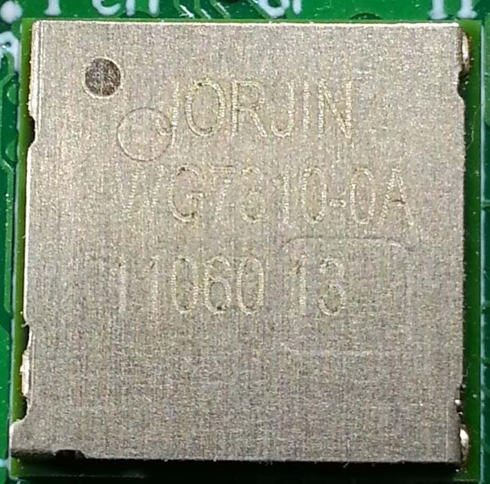
Click to zoom
Application Details
- Equipment Class
- DXT - Part 15 Low Power Transceiver, Rx Verified
- Date of Grant
- Aug 14, 2014
- Application Purpose
- Original Equipment
- Date of Application
- Aug 14, 2014
- Equipment Note
- WiFi Bluetooth Module
- Frequency Range
- 2412.00000000 - 2462.00000000
- Company
- HandEra, Inc.
- Country
- United States
Documents & Files
Document Text
Text extracted from the exhibit documents filed with the FCC. Open a document above to read the original.
Users Manual
1007-00078 Revision 1.0 WF-10040 User Manual 2 WF-10040 Description of changes Rev. Date First Release 1.0 05/01/14 3 WF-10040 Contents 1. Introduction ............................................................................................................................................ 4 1.1 Purpose and Scope .......................................................................................................... 4 1.2 Audience ........................................................................................................................... 4 1.3. Reference Documents ......................................................................................................... 4 2. EMC Compliance Guide ........................................................................................................................ 4 2.1 Introduction ....................................................................................................................... 4 2.2 Module Integration Considerations – Firmware ............................................................... 4 2.3 Antenna ............................................................................................................................ 5 2.4 Circuit Implementation ...................................................................................................... 5 2.5 Top Assembly Implementation ......................................................................................... 5 2.6 Marking Requirements for End-Product and Compliance Statements ............................ 5 2.6.2 Agency Certifications ................................................................................................................ 5 2.6.1 Operating Requirements and Conditions ..................................................................................... 5 2.6.2 Agency Certifications: ................................................................................................................... 5 2.6.3 Mobile Device RF Exposure Statement: ....................................................................................... 5 2.6.4 Caution Statement for Modifications: ............................................................................................ 5 2.6.5 FCC Part 15 Statement: ............................................................................................................... 6 2.6.6 IC Statements ............................................................................................................................... 6 2.6.7 Responsibilities to Comply with FCC and Industry Canada Regulations ..................................... 6 2.6.8 End Product Labeling ................................................................................................................... 7 4 WF-10040 1. Introduction 1.1 Purpose and Scope The purpose of this document is to provide details on how to integrate this module into a design. The module includes a wireless transceiver chip (Jorjin WG3710) and antenna (Antenova 3030A5839-01) that will be placed on a printed circuit board (PCB) and interface with a CPU. This document will provide guidance on how to maintain regulatory compliance. 1.2 Audience This document is intended for HandEra engineers. 1.3. Reference Documents 1. Jorjin WG7310 Datasheet 2. Antenova 3030A5839-01 Datasheet 3. Test board schematics (HandEra P/N 2400-00348) 4. Test board layout (HandEra P/N 2400-00348) 2. EMC Compliance Guide 2.1 Introduction This module has been tested as a Modular Radio in accordance with the FCC and IC. This allows HandEra to integrate this module into a product and only be responsible for Unintentional Emissions produced by this product as long as the recommendations in this guide are followed. 2.2 Module Integration Considerations – Firmware The module must use specific operational firmware. This firmware includes: 1. BRF61_7.2.31.bts 2. FW1273_CHIP.bin (Rev. 6.1.0.1.349) 5 WF-10040 2.3 Antenna This module must use the Antenova 3030A5839-01 or an antenna of the same type with equal or lesser gain. All requirements from the datasheet, including ground plane clearance must be followed. 2.4 Circuit Implementation All requirements from the Jorjin WG7310 datasheet must be followed along with best engineering practices. The HandEra test board schematics and layout should be followed as closely as possible. 2.5 Top Assembly Implementation In addition to the recommendations given for the antenna systems and the module placement onto a product PCB, it is recommended that all wiring and interconnect systems within the product be not routed anywhere close the module and its associated circuitry on the PCB, doing so could change the emission characteristics of the module. 2.6 Marking Requirements for End-Product and Compliance Statements 2.6.2 Agency Certifications FCC ID: 2.6.1 Operating Requirements and Conditions The design of RB-C220 complies with U.S. Federal Communications Commission (FCC) guidelines respecting safety levels of radio frequency (RF) exposure for Mobile 2.6.2 Agency Certifications: FCCID: URZ-WF10040 IC ID: 6827A-WF10040 2.6.3 Mobile Device RF Exposure Statement: RF Exposure - This device is only authorized for use in a mobile application. At least 20 cm of separation distance between the RB-C220 device and the user's body must be maintained at all times. 2.6.4 Caution Statement for Modifications: 6 WF-10040 CAUTION: Any changes or modifications not expressly approved by Intoxalock could void the user’s authority to operate the equipment. 2.6.5 FCC Part 15 Statement: Note: This equipment has been tested and found to comply with the limits for a Class B digital device, pursuant to Part 15 of the FCC Rules. 2.6.6 IC Statements Operation is subject to the following two conditions: (1) this device may not cause interference, and (2) this device must accept any interference, including interference that may cause undesired operation of the dev…
Text truncated - open the document above for the full version.
Users Manual
Regulatory Module Integration Instructions This module has been granted modular approval for mobile applications. OEM integrators for host products may use the module in their final products without additional FCC / IC (Industry Canada) certification if they meet the following conditions. Otherwise, additional FCC / IC approvals must be obtained. • The host product with the module installed must be evaluated for simultaneous transmission requirements. • The users manual for the host product must clearly indicate the operating requirements and conditions that must be observed to ensure compliance with current FCC / IC RF exposure guidelines. • To comply with FCC / IC regulations limiting both maximum RF output power and human exposure to RF radiation, the maximum antenna gain including cable loss in a mobile- only exposure condition must not exceed 2.1 dBi (tested with Antenova P/N 3030A5839- 01) • A label must be affixed to the outside of the host product with the following statements: This device contains FCCID: URZ-WF10040 This equipment contains equipment certified under ICID: 6827A-WF10040 The final host / module combination may also need to be evaluated against the FCC Part 15B criteria for unintentional radiators in order to be properly authorized for operation as a Part 15 digital device. If the final host / module combination is intended for use as a portable device (see classifications below) the host manufacturer is responsible for separate approvals for the SAR requirements from FCC Part 2.1093 and RSS-102. Device Classifications Since host devices vary widely with design features and configurations module integrators shall follow the guidelines below regarding device classification and simultaneous transmission, and seek guidance from their preferred regulatory test lab to determine how regulatory guidelines will impact the device compliance. Proactive management of the regulatory process will minimize unexpected schedule delays and costs due to unplanned testing activities. The module integrator must determine the minimum distance required between their host device and the user’s body. The FCC provides device classification definitions to assist in making the correct determination. Note that these classifications are guidelines only; strict adherence to a device classification may not satisfy the regulatory requirement as near-body device design details may vary widely. Your preferred test lab will be able to assist in determining the appropriate device category for your host product and if a KDB or PBA must be submitted to the FCC. Note, the module you are using has been granted modular approval for mobile applications. Portable applications may require further RF exposure (SAR) evaluations. It is also likely that the host / module combination will need to undergo testing for FCC Part 15 regardless of the device classification. Your preferred test lab will be able to assist in determining the exact tests which are required on the host / module combination. FCC Definitions Portable: (§2.1093) — A portable device is defined as a transmitting device designed to be used so that the radiating structure(s) of the device is / are within 20 centimeters of the body of the user. Mobile: (§2.1091) (b) — A mobile device is defined as a transmitting device designed to be used in other than fixed locations and to generally be used in such a way that a separation distance of at least 20 centimeters is normally maintained between the transmitter’s radiating structure(s) and the body of the user or nearby persons. Per §2.1091d(d)(4) In some cases (for example, modular or desktop transmitters), the potential conditions of use of a device may not allow easy classification of that device as either Mobile or Portable. In these cases, applicants are responsible for determining minimum distances for compliance for the intended use and installation of the device based on evaluation of either specific absorption rate (SAR), field strength, or power density, whichever is most appropriate. Simultaneous Transmission Evaluation This module has not been evaluated or approved for simultaneous transmission as it is impossible to determine the exact multi-transmission scenario that a host manufacturer may choose. Any simultaneous transmission condition established through module integration into a host product must be evaluated per the requirements in KDB447498D01(8) and KDB616217D01,D03 (for laptop, notebook, netbook, and tablet applications). These requirements include, but are not limited to: • Transmitters and modules certified for mobile or portable exposure conditions can be incorporated in mobile host devices without further testing or certification when: • The closest separation among all simultaneous transmitting antennas is >20 cm, Or • Antenna separation distance and MPE compliance requirements for ALL simultaneous transmitting antennas have been specified in the application filing of at least one of the certified transmitters within the host device. In addition, when transmitters certified for portable use are incorporated in a mobile host device, the antenna(s) must be >5 cm from all other simultaneous transmitting antennas. • All antennas in the final product must be at least 20 cm from users and nearby persons. OEM Instruction Manual Content Consistent with §2.909(a), the following text must be included within the user’s manual or operator instruction guide for the final commercial product (OEM-specific content is displayed in italics.) Operating Requirements and Conditions: The design of RB-C220 complies with U.S. Federal Communications Commission (FCC) guidelines respecting safety levels of radio frequency (RF) exposure for Mobile FCC ID: This product contains FCCID: URZ-WF10040 Mobile Device RF Exposure Statement (If Applicable): RF Exposure - This device is only authorized for use in a mobile application. At least 20 cm of separation distance between the RB-C220 device and the user's bod…
Text truncated - open the document above for the full version.
Block Diagram
WG7310 DC2DC 38.4 MHz XTAL BPF TX RX VBAT VIO Slow CLK Host I/F Host Signalling Debug I/F WL1271 WLAN BT FM Buffers WL1271 FE PA (b/g/n) SW Block Diagram
ID Label/Location Info
1008-00080 Revision 1.0 WF-10040 Label Placement Instructions TITLE: WF-10040 WiFi Module Labeling Instructions AUTHOR: Scott Lyle Date: 6/17/2014 REVISION: 01 TOOLS REQUIRED: ESD Wrist Strap 2110-00168 FCC/ICID Label for WF-10040 WiFi Module Tweezers for applying label STEP 1: Locate the Jorjin module on the PCB. The module will look like the Jorjin module in picture below. STEP 2: Apply the FCC/ICID Label (2110-00168) as shown.
Operational Description
1007-00079 Revision 1.0 WF-10040 Technical Operational Description 2 WF10040 Description of changes Rev. Date First Release 1.0 05/01/14 3 WF10040 Contents 1. Summary ................................................................................................................................................ 4 2. Antenna .................................................................................................................................................. 4 3. Installation ............................................................................................................................................. 4 4. Grounding .............................................................................................................................................. 4 5. Power ..................................................................................................................................................... 4 6. Transmissions ........................................................................................................................................ 4 4 WF10040 1. Summary The WF-10040 module is a Jorjin WG7310 chip paired with an Antenova 3030A5839-01 antenna. It will be integrated into in HandEra designs. 2. Antenna The Jorjin WG7310 chip is connected to an Antenova 3030A5839-01 2.45 GHz left side feed chip antenna that is used for wireless transmissions. The ground plane on the PCB that contains the module must not extend below the antenna as described in the datasheet for that part. 3. Installation This module is intended to be installed on a printed circuit board (PCB). All recommendations in section 10 of the Jorjin WG7310 datasheet must be followed. All routing and placement recommendations in the Antenova 3030A5839-01 must be followed as well. The module may communicate with a CPU on a different PCB using a board to board connector or cable for inter- module communications. 4. Grounding The Jorjin chip must be connected to the digital ground plane of the PCB it is integrated into. A cutout around the antenna must be maintained as described in the Antenova 3030A5839-01 datasheet. 5. Power The Jorjin chip must be powered as described in section 6 of the Jorjin WG7310 datasheet. The wireless radio power is handled internally by the Jorjin chip. 6. Transmissions The WiFi module supports IEEE 802.11b/g/n and BT v2.1 EDR transmissions. A CPU module communicates with the Jorjin WG7310 chip using an SDIO or SPI interface for WiFi communications and a UART interface for Bluletooth communications. The wireless transmissions are generated by the Jorjin WG7310 chip using the firmware referenced in the User’s Manual.
RF Exposure Info
731 Enterprise Drive Lexington, KY 40510 Telephone: 859-226-1000 Facsimile: 859-226-1040 www.intertek-etlsemko.com MPE Calculation § 1.1310: The criteria listed in table 1 shall be used to evaluate the environmental impact of human exposure to radiofrequency (RF) radiation as specified in §1.1307(b), except in the case of portable devices which shall be evaluated according to the provisions of §2.1093 of this chapter. Part 1.1310 Limits for Maximum Permissible Exposure (MPE) 1.1 Test Procedure An MPE evaluation for was performed in order to show that the device was compliant with §2.1091. The maximum power density was calculated for each transmitter at a separation distance of 20cm. For each transmitter the maximum RF exposure was calculated at a 20 cm distance using the formula: 10/)( 10 dBmowerConductedP mW PowerConducted= 2 )20(4 . cm mW GainAntPowerConducted tyPowerDensi × × = π 731 Enterprise Drive Lexington, KY 40510 Telephone: 859-226-1000 Facsimile: 859-226-1040 www.intertek-etlsemko.com 1.2 Results (802.11 Radio): • Maximum Conducted Output Power = 319.2mW • Maximum Antenna Gain = 2.1dBi Power Density = (319.2mW x 2.1dBi) / 5025.6 Power Density = 0.133mW/cm 2 Limit at 2.4GHz = 1mW/cm 2 The calculated maximum power density at 20cm distance is less that the limit for general population / uncontrolled exposure. 1.3 Results (Bluetooth Radio): • Maximum Conducted Output Power = 9.74mW • Maximum Antenna Gain = 2.1dBi Power Density = (9.74mW x 2.1dBi) / 5025.6 Power Density = 0.mW/cm 2 Limit at 2.4GHz = 0.004mW/cm 2 The calculated maximum power density at 20cm distance is less that the limit for general population / uncontrolled exposure. 1.4 Results (Simultaneous Transmission) The sum or the power densities for the Bluetooth and 802.11 radios is less than the MPE limit at 2.4GHz as shown below: 0.133mW/cm 2 + 0.004mW/cm 2 = 0.137 mW/cm 2
Test Report
This report is for the exclusive use of Intertek's Client and is provided pursuant to the agreement between Intertek and its Client. Intertek's responsibility and liability are limited to the terms and conditions of the agreement. Intertek assumes no liability to any party, other than to the Client in accordance with the agreement, for any loss, expense or damage occasioned by the use of this report. Only the Client is authorized to permit copying or distribution of this report and then only in its entirety. Any use of the Intertek name or one of its marks for the sale or advertisement of the tested material, product or service must first be approved in writing by Intertek. The observations and test results in this report are relevant only to the sample tested. This report by itself does not imply that the material, product, or service is or has ever been under an Intertek certification program. EMC Report for HandEra, Inc. on the WF10040 WiFi, Bluetooth Module Page 1 of 47 731 Enterprise Drive Lexington, KY 40510 Telephone: 859-226-1000 Facsimile: 859-226-1040 www.intertek-etlsemko.com TEST REPORT Report Number: 101159678LEX-001 Project Number: G101159678 Report Issue Date: 6/3/2014 Product Name: WF10040 WiFi, Bluetooth Module FCCID: URZ-WF10040 ICID: 68270-WF10040 Standards: Radio Under Test: CFR Title 47 Part 15 C, RSS 210-Issue 8 WiFi Tested by: Client: Intertek Testing Services NA, Inc. 731 Enterprise Drive Lexington, KY 40510 HandEra, Inc. 2859 104th St Des Moines, IA 50322 Report prepared by Report reviewed by Toby Carrier, Technician Bryan Taylor, Team Leader Intertek Report Number: 101159678LEX-001 Issued: 6/3/2014 EMC Report for HandEra, Inc. on the WF10040 WiFi, Bluetooth Module FCCID:URZ-WF10040; ICID:68270-WF10040 Page 2 of 47 TABLE OF CONTENTS 1 Introduction and Conclusion .............................................................................................................. 3 2 Test Summary ...................................................................................................................................... 3 3 Description of Equipment Under Test ............................................................................................... 4 4 Peak Conducted Power ....................................................................................................................... 6 5 Occupied Bandwidth ........................................................................................................................... 8 6 Conducted Spurious Emissions ....................................................................................................... 15 7 Power Spectral Density ..................................................................................................................... 24 8 Radiated Spurious Emissions (Transmitter) ................................................................................... 30 9 Radiated Spurious Emissions (Receiver) ........................................................................................ 38 10 AC Powerline Conducted Emissions ........................................................................................... 42 11 Antenna Requirement per FCC Part 15.203 ................................................................................. 45 12 Measurement Uncertainty.............................................................................................................. 46 13 Revision History ............................................................................................................................. 47 Intertek Report Number: 101159678LEX-001 Issued: 6/3/2014 EMC Report for HandEra, Inc. on the WF10040 WiFi, Bluetooth Module FCCID:URZ-WF10040; ICID:68270-WF10040 Page 3 of 47 1 Introduction and Conclusion The tests indicated in section 2 were performed on the product constructed as described in section 3. The remaining test sections are the verbatim text from the actual data sheets used during the investigation. These test sections include the test name, the specified test method, a list of the actual test equipment used, documentation photos, results and raw data. No additions, deviations, or exclusions have been made from the standard(s) unless specifically noted. Based on the results of our investigation, we have concluded the product tested complied with the requirements of the standard(s) indicated. The results obtained in this test report pertain only to the item(s) tested. The INTERTEK-Lexington is located at 731 Enterprise Drive, Lexington Kentucky, 40510. The radiated emission test site is a 10-meter semi-anechoic chamber. The chamber meets the characteristics of CISPR 16-1 and ANSI C63.4. For measurements, a remotely controlled flush-mount metal-top turntable is used to rotate the EUT a full 360 degrees. A remote controlled non-conductive antenna mast is used to scan the antenna height from one to four meters. The test site is listed with the FCC under registration number 485103. The test site is listed with Industry Canada under site number IC 2042M-1. 2 Test Summary Page Test full name FCC Reference IC Reference Result 6 Peak Conducted Power § 15.247(b)(3)(4) RSS-210 (A8.4) Pass 8 Occupied Bandwidth § 15.247(a)(2) RSS-210 (A8.2), RSS-GEN (4.6.1) Pass 15 Conducted Spurious Emissions § 15.247(d) RSS-210 (A8.5) Pass 24 Power Spectral Density § 15.247(e) RSS-210 (A8.2b) Pass 30 Radiated Spurious Emissions (Transmitter) § 15.247(d), § 15.209, and § 15.205 RSS-210 (2.2) (A8.5) Pass 38 Radiated Spurious Emissions (Receiver) § 15.109 RSS-Gen (6.1) Pass 42 AC Powerline Conducted Emissions § 15.107, § 15.207 RSS-Gen (7.2.4) Pass 45 Antenna Requirement per FCC Part 15.203 § 15.203 RSS-Gen (7.1.2) Pass Intertek Report Number: 101159678LEX-001 Issued: 6/3/2014 EMC Report for HandEra, Inc. on the WF10040 WiFi, Bluetooth Module FCCID:URZ-WF10040; ICID:68270-WF10040 Page 4 of 47 3 Description of Equipment Under Test Equipment Under Test Manufacturer Hand…
Text truncated - open the document above for the full version.
Test Report
This report is for the exclusive use of Intertek's Client and is provided pursuant to the agreement between Intertek and its Client. Intertek's responsibility and liability are limited to the terms and conditions of the agreement. Intertek assumes no liability to any party, other than to the Client in accordance with the agreement, for any loss, expense or damage occasioned by the use of this report. Only the Client is authorized to permit copying or distribution of this report and then only in its entirety. Any use of the Intertek name or one of its marks for the sale or advertisement of the tested material, product or service must first be approved in writing by Intertek. The observations and test results in this report are relevant only to the sample tested. This report by itself does not imply that the material, product, or service is or has ever been under an Intertek certification program. EMC Report for HandEra, Inc. on the WF10040 WiFi, Bluetooth Module Page 1 of 49 731 Enterprise Drive Lexington, KY 40510 Telephone: 859-226-1000 Facsimile: 859-226-1040 www.intertek-etlsemko.com FHSS TEST REPORT Report Number: 101159678LEX-002 Project Number: G101159678 Report Issue Date: 6/3/2014 Product Name: WF10040 WiFi, Bluetooth Module FCCID: ICID: URZ-WF10040 68270-WF10040 Standards: Radio Under Test: CFR Title 47 Part 15 B and C, RSS 210-Issue 8 Bluetooth Tested by: Client: Intertek Testing Services NA, Inc. 731 Enterprise Drive Lexington, KY 40510 HandEra, Inc. 2859 104th St Des Moines, IA 50322 Report prepared by Report reviewed by Toby Carrier, Technician Bryan Taylor, Team Leader Intertek Report Number: 101159678LEX-002 Issued: 6/3/2014 EMC Report for HandEra, Inc. on the WF10040 WiFi, Bluetooth Module FCCID:URZ-WF10040 Page 2 of 49 TABLE OF CONTENTS 1 Introduction and Conclusion .............................................................................................................. 3 2 Test Summary ...................................................................................................................................... 3 3 Description of Equipment Under Test ............................................................................................... 4 4 Peak Output Power .............................................................................................................................. 6 5 20dB Bandwidth ................................................................................................................................. 12 6 Channel Separation ........................................................................................................................... 15 7 Number of Hopping Channels .......................................................................................................... 17 8 Time of Occupancy ............................................................................................................................ 21 9 Conducted Spurious Emissions ....................................................................................................... 25 10 Radiated Spurious Emissions (Transmitter) ............................................................................... 34 11 Radiated Spurious Emissions (Receiver) .................................................................................... 40 12 AC Powerline Conducted Emissions ........................................................................................... 44 13 Antenna Requirement per FCC Part 15.203 ................................................................................. 47 14 Measurement Uncertainty.............................................................................................................. 48 15 Revision History ............................................................................................................................. 49 Intertek Report Number: 101159678LEX-002 Issued: 6/3/2014 EMC Report for HandEra, Inc. on the WF10040 WiFi, Bluetooth Module FCCID:URZ-WF10040 Page 3 of 49 1 Introduction and Conclusion The tests indicated in Section 2 were performed on the product constructed as described in Section 3. The remaining test sections are the verbatim text from the actual data sheets used during the investigation. These test sections include the test name, the specified test method, a list of the actual test equipment used, documentation photos, results and raw data. No additions, deviations, or exclusions have been made from the standard(s) unless specifically noted. Based on the results of our investigation, we have concluded the product tested complied with the requirements of the standard(s) indicated. The results obtained in this test report pertain only to the item(s) tested. The INTERTEK-Lexington facility is located at 731 Enterprise Drive, Lexington Kentucky, 40510. The radiated emission test site is a 10-meter semi-anechoic chamber. The chamber meets the characteristics of CISPR 16-1 and ANSI C63.4. For radiated measurements, a remotely controlled flush-mount metal-top turntable is used to rotate the EUT a full 360 degrees. A remote controlled non-conductive antenna mast is used to scan the antenna height from one to four meters. The test site is listed with the FCC under registration number 485103. The test site is listed with Industry Canada under site number IC 2042M-1. 2 Test Summary Page Test full name FCC Reference IC Reference Result 6 Peak Output Power § 15.247(b)(1) RSS210 (A8.4) Pass 12 20dB Bandwidth § 15.247(a)(1) RSS210 (A8.1) Pass 15 Channel Separation § 15.247(a)(1) RSS210 (A8.1) Pass 17 Number of Hopping Channels § 15.247(a)(1)(iii) RSS210(A8.1) Pass 21 Time of Occupancy § 15.247(a)(1)(iii) RSS210 (A8.1) Pass 25 Conducted Spurious Emissions § 15.247(d) RSS210 (A8.5) Pass 34 Radiated Spurious Emissions (Transmitter) § 15.247(d), § 15.209, and § 15.205 RSS-210 (A8.5) Pass 40 Radiated Spurious Emissions (Receiver) § 15.109 RSS-Gen (6.1) Pass 44 AC Powerline Conducted E…
Text truncated - open the document above for the full version.
Contact Information
Applicant
Mark Kubovich(President)
Technical Contact
HandEra, IncDoug DeVries
[email protected]515-252-7522
2859 104th ST · Des Moines, Massachusetts · United States
Non-Technical Contact
HandEra, IncScott Lyle
[email protected]515-252-7522
Test Firm
Intertek Testing Services NAJames Sudduth
Technical Specifications
| # | Rule Parts | Frequency Range | Power Output |
|---|---|---|---|
| 1 | 15C | 2.41 GHz - 2.46 GHz | 178.60 mW |
Other Applications from HandEra, Inc.

URZ-WF10011
Dec 05, 2006802.11b Wi-Fi Module
Equipment Class
DTS - Digital Transmission System