USE313110Long Range Reader
Paxton Access Ltd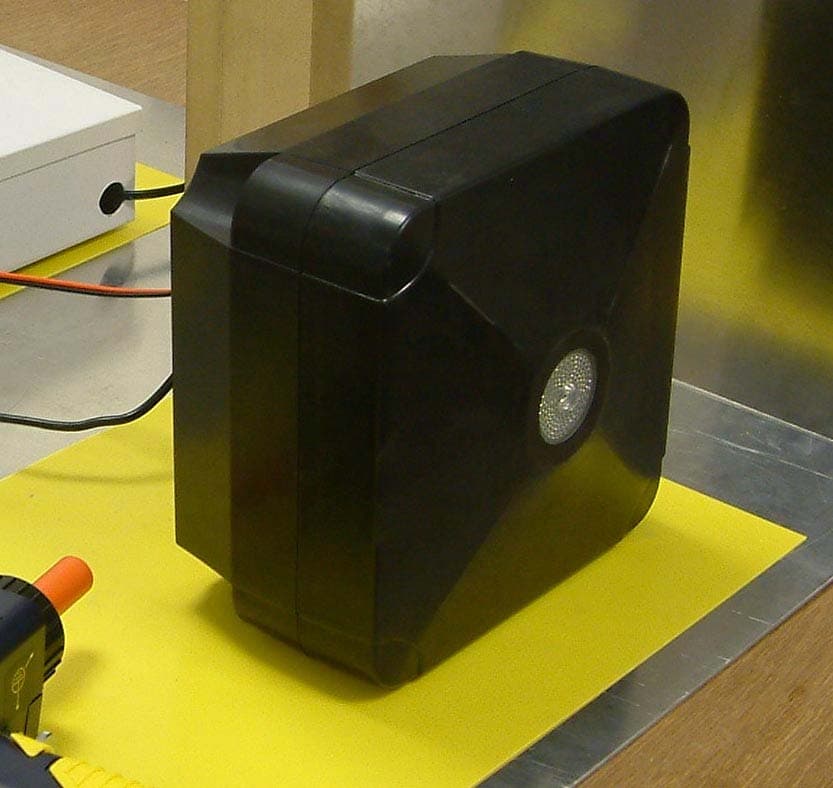
Click to zoom
Application Details
- Equipment Class
- DCD - Part 15 Low Power Transmitter Below 1705 kHz
- Date of Grant
- Mar 09, 2008
- Application Purpose
- Original Equipment
- Date of Application
- Mar 09, 2008
- Equipment Note
- Long Range Reader
- Frequency Range
- 0.12500000 - 0.12500000
- Company
- Paxton Access Ltd
- Country
- United Kingdom
Documents & Files
Document Text
Text extracted from the exhibit documents filed with the FCC. Open a document above to read the original.
Users Manual
Ins-30060-US Long range reader 21/01/2008 What is Hands Free? A long range reader can read Paxton hands free tokens up to a maximum of 5 yards. The system comprises of a long range reader with an integral hands free interface and hands free tokens (keycard or keyfob). The system operates by using the field being transmitted by the reader to wake up the token which then communicates with the interface. Existing Switch2 or Net2 control units, can be used without modification. Standard Paxton tokens/keyfobs can be used with this reader but at their normal read range (see table on back page) Hands free tokens also include a standard proximity ID chip and can therefore be presented to any Paxton LED indications The unit has a single high intensity LED array that displays RED or GREEN indications. Steady RED - Waiting for card ( IDLE state ) Flashing GREEN - Access Granted ( or held unlocked ) Flashing RED - User Access Denied If an error condition exists ( ACU powered off, Cable break, etc) the LED will show a steady RED indication. Layout Technical Support Technical help is available: Monday - Friday from 5am - 11pm PST / 8am - 2am EST Saturday from 7am - 11am PST / 10am - 2pm EST Documentation on all Paxton Access products can be found on our web site - http://www.paxton-access.com/ 1 800 672 PAXT [email protected] 12v Red LED Amber LED Green LED Data/D0 Net2 Co ntrol Unit Clock/D1 Media Detect 0V Entry 12v Red LED Amber LED Green LED Data/D0 Clock/D1 Media Detect 0V Entry Green LEDExit/Ent ry 0V12V Net2Air Interface Reader Red 12v dc Brown Keypad 2Reader 2 Orange Green Yellow Blue Mauve Black/White Brown Yellow Orange +12V 0V N.C.- N.O.- Com N.C.- N.O.- Com Alarm Output 0V Contact 0V Exit 0V Tamper PSU RX TX Rela y 1 Rela y 2 Exi t Co ntac t Ta mper PSUOK5V12V Re d Brow n OrangeGreenY ellow BlueMauv e Black/Whit e Brow n Y ellow Orange Networ k j CA T5 Cable coding White/Green Green White/Orange Orange 1 2 3 4 Screen or spare cores from network cable Seriel number241821Te stID: 012345678901 z-14401 3 2 4 8 9 8 0 0 0 0 0 4 Po we r Rela y 1 Rela y 2 Inputs 12Vdc Power Supply Not Connected Not Conne cted Not Conne cted Reader 1 Keypad 1 Caution: F or 12V d.c readers only . Fo r connec tion of old 5v readers , ref er to instruc tion s 12v Red LED Amber LED Green LED Data/D0 Net2 Co ntrol Unit Clock/D1 Media Detect 0V Entry 12v Red LED Amber LED Green LED Data/D0 Clock/D1 Media Detect 0V Entry Green LEDExit/Ent ry 0V12V Net2Air Interface Reader Red 12v dc Brown Keypad 2Reader 2 Orange Green Yellow Blue Mauve Black/White Brown Yellow Orange +12V 0V N.C.- N.O.- Com N.C.- N.O.- Com Alarm Output 0V Contact 0V Exit 0V Tamper PSU RX TX Rela y 1 Rela y 2 Exi t Co ntac t Ta mper PSUOK5V12V Re d Brow n OrangeGreenY ellow BlueMauv e Black/Whit e Brow n Y ellow Orange Networ k j CA T5 Cable coding White/Green Green White/Orange Orange 1 2 3 4 Screen or spare cores from network cable Seriel number241821Te stID: 012345678901 z-14401 3 2 4 8 9 8 0 0 0 0 0 4 Po we r Rela y 1 Rela y 2 Inputs 12Vdc Power Supply Not Connected Not Conne cted Not Conne cted Reader 1 Keypad 1 Caution: F or 12V d.c readers only . Fo r connec tion of old 5v readers , ref er to instruc tion s Wiring It is important to run an appropriate power cable to the reader that is capable of carrying a current of 1A. A data cable must be run from the control unit to the reader interface. The recommended cable for this is Belden 9540; a 10 core overall screened cable with a maximum cable length of 100 yards. Spare cores should be used to double up on the power wires (Red/Black) to the interface. The reader requires a higher current (up to 1A) than can be supplied by the ACU reader port and so an independent 12V DC power feed must be provided. As per the wiring diagram, the spare outputs on the Paxton 2A boxed power supply can be used for this purpose. Before you install Read in, read out When using in and out readers, users may be picked up by both readers as they move through the door which will effect the reliability of any Roll Call or Antipassback application. Ensure that sufficient spacing is provided between these readers for optimum range and reliability. Positioning readers For maximum read range the Hands Free reader field should not be overlapped by the field from other interference sources at or around 125KHz. These include Loop readers, non Paxton readers, etc. Readers should not positioned so that their active fields overlap. (see table on back page for typical hand free read ranges) For optimum keyfob battery life please choose your reader location carefully to avoid placing it within hands free range of work stations, rest or smoking areas. NOTE: Each long range reader requires a dedicated ACU reader port. To achieve the maximum range for the device, the interface PCB has been mounted upside down to position the internal aerial away from other reader components. Fitting 1 2 3 4 Determine the position of the reader and mark and drill holes for the fixing screws and cable access. Fix the mounting plate to the post with the locating hooks at the top. (Fig 1) Feed the cables for power and data thorough the mounting plate and into the rear section of the reader leaving enough slack to allow easy connection to the circuit boards later in the installation. Tighten the weatherproof cable glands at the rear of the reader. (Fig 2) Hang the rear reader section on the mounting plate and secure with two screws. (Fig 3) Complete the wiring of the reader as shown in this instruction. Join the front section to the rear section with the Allen screws provided. (Fig 4) NOTE: It may be necessary to briefly remove the reader from its mounting plate if access to the Allen screws is limited by the post or wall. The long range reader consists of a reader module mounted inside the front half of the housing and a hands free interface mounted inside the rear half. An interconnect cable is supplied that connects the two sections together. Two 5 yard cables…
Text truncated - open the document above for the full version.
Cover Letter(s)
1(1) Attention: Application Examiner Re: Request for confidentiality Applicant: Paxton Access Ltd FCC ID: USE313110 21 st December 2007 To whom it may concern, Permanent Confidentiality Request is hereby submitted by Paxton Access Ltd to withhold permanently from public review certain portions of the application for equipment certification for the referenced FCC identifiers. This request for confidentiality is made pursuant to 47 CFR 0.457(d) and 0.459 of the FCC Rules. In particular, the following sections of the application are to be kept permanently confidential: 1. Schematics 2. Detailed Block diagrams 3. Detailed Operational/Functional Description 4. Parts Lists 5. Internal Photos Rationale for request for confidentiality of all items above. Paxton Access Ltd has invested considerable time and materials in research and development to produce the referenced product. Disclosure of the permanently confidential portions of this application to competitors would not only give them significant competitive advantages in developing similar products, but would also disclose successful implementation of unpublished, leading edge technology developed by us. Sincerely, Quality Manager Paxton Access Ltd
External Photos
Exhibit 3: External Photographs Front view Rear view (without mounting backplate, showing cables) Rear view (with mounting backplate) Isometric view
ID Label/Location Info
Exhibit 1: ID Label – location information Located on the back of the reader.
Parts List/Tune Up Info
Changing frequency channel If you are experiencing problems with the range or reliability this may be due to poor reader positioning, adjacent interfering 125KHz or 2.4 GHz equipment, e.g. an adjacent wireless PC network. Please refer to the ‘Before you install’ information regarding unit locations. If you are still unable to improve the system performance then you may try an alternative 2.4 GHz channel using Switch 1. Power cycle the unit after any changes. The system has 16 different channels available. The unit is set to channel 4 as this frequency is normally clear of other device transmissions. This can be changed using a small flat blade screwdriver. Take care not to contact the circuit board with the screwdriver blade as this may damage components. 02.40511 12.4112 22.41513 32.4214 42.42515 52.4316 62.43517 72.4418 82.44519 92.4520 A2.45521 B2.4622 C2.46523 D2.4724 E2.47525 F2.4826 SW1. Rotate the switch to select an alternate channel. All hands free tokens automatically configure themselves to use the new channel. No configuration of the token is required. GHz Switch position The switch will initially be set to default position ‘4’ IEEE 802.15.4 channel Keycard configuration The switch SW2 is used to configure the buttons on the hands free Keycard. Please refer to instruction sheet ins-30037 for switch configuration supplied with the keycard. SW2 The unit must be power cycled if the switch position is changed to reconfigure the settings. Configuration Frequency Tune-up Information
Test Report
TEST REPORT FROM RFI GLOBAL SERVICES LTD Test of: Paxton Access Ltd PROXIMITY Long Range Reader To: FCC Part 15.107: 2007, Part 15.109: 2007 and Part 15.249: 2007 (Subpart C) Test Report Serial No: RFI/RPTE3/RP49342JD08A Supersedes Test Report Serial No: RFI/RPTE2/RP49342JD08A This Test Report Is Issued Under The Authority Of Steve Flooks, Radio Performance Group Service Leader: Checked By: Steve Flooks Report Copy No: PDF01 Issue Date: 05 March 2008 Test Dates: 12 November 2007 to 19 November 2007 This report is issued in Adobe Acrobat portable document format (PDF). It is only a valid copy of the report if it is being viewed in PDF format with the following security options not allowed: Changing the document, Selecting text and graphics, Adding or changing notes and form fields. This report may be copied in full. The results in this report apply only to the sample(s) tested. RFI GLOBAL SERVICES LTD TEST REPORT S.No. RFI/RPTE3/RP49342JD08A Page: 2 of 26 Issue Date: 05 March 2008 Test of: Paxton Access Ltd PROXIMITY Long Range Reader To: FCC Part 15.107: 2007, Part 15.109: 2007 and Part 15.249: 2007 (Subpart C) This page has been left intentionally blank. RFI GLOBAL SERVICES LTD TEST REPORT S.No. RFI/RPTE3/RP49342JD08A Page: 3 of 26 Issue Date: 05 March 2008 Test of: Paxton Access Ltd PROXIMITY Long Range Reader To: FCC Part 15.107: 2007, Part 15.109: 2007 and Part 15.249: 2007 (Subpart C) Table of Contents 1. Client Information ............................................................................................................................4 2. Equipment Under Test (EUT) ..........................................................................................................5 3. Test Specification, Methods and Procedures ...............................................................................7 4. Deviations from the Test Specification..........................................................................................7 5. Operation of the EUT During Testing.............................................................................................8 6. Summary of Test Results ................................................................................................................9 7. Measurements, Examinations and Derived Results ...................................................................10 8. Measurement Uncertainty .............................................................................................................20 9. Measurement Methods ..................................................................................................................21 Appendix 1. Test Equipment Used ...................................................................................................23 Appendix 2. Test Configuration Drawings.......................................................................................24 RFI GLOBAL SERVICES LTD TEST REPORT S.No. RFI/RPTE3/RP49342JD08A Page: 4 of 26 Issue Date: 05 March 2008 Test of: Paxton Access Ltd PROXIMITY Long Range Reader To: FCC Part 15.107: 2007, Part 15.109: 2007 and Part 15.249: 2007 (Subpart C) 1. Client Information Company Name: Paxton Access Ltd Address: Paxton House Home Farm Brighton Sussex BN1 9HU Contact Name: Mr B Glass RFI GLOBAL SERVICES LTD TEST REPORT S.No. RFI/RPTE3/RP49342JD08A Page: 5 of 26 Issue Date: 05 March 2008 Test of: Paxton Access Ltd PROXIMITY Long Range Reader To: FCC Part 15.107: 2007, Part 15.109: 2007 and Part 15.249: 2007 (Subpart C) 2. Equipment Under Test (EUT) The following information (with the exception of the Date of Receipt) has been supplied by the client: 2.1. Identification of Equipment Under Test (EUT) Description: Hands Free Access Control Reader Brand Name: PROXIMITY Long Range Reader Model Name or Number: 313-110 Serial Number: None Stated FCC ID Number: USE313110 Country of Manufacture: UK Date of Receipt: 12 November 2007 2.2. Description of EUT The equipment under test was a Hands Free Access Control Reader. 2.3. Modifications Incorporated in the EUT During the course of testing the EUT was not modified. RFI GLOBAL SERVICES LTD TEST REPORT S.No. RFI/RPTE3/RP49342JD08A Page: 6 of 26 Issue Date: 05 March 2008 Test of: Paxton Access Ltd PROXIMITY Long Range Reader To: FCC Part 15.107: 2007, Part 15.109: 2007 and Part 15.249: 2007 (Subpart C) 2.4. Additional Information Related to Testing Power Supply Requirement: DC Supply of 12V DC Equipment Category: IEEE 802.15.4 Type of Unit: Base Station (Fixed use) Transceiver Channel Spacing: 5MHz Spacing for 2.4GHz Power Characteristics: 1mW (maximum rating) Modulation Type: Amplitude Modulation (12kHz, DSSS (2.4GHz) Data Rate: 600 μs Temperature Range: -20°C to 55°C Transmit Frequency Range: 2405MHz to 2480MHz 125kHz Single Channel Channel ID Channel Number Channel Frequency (MHz) Bottom 11 2405 Middle 18 2440 Transmit Channels Tested: Top 26 2480 Receive Frequency Range: 2405MHz to 2480MHz Channel ID Channel Number Channel Frequency (MHz) Bottom 11 2405 Middle 18 2440 Receive Channels Tested: Top 26 2480 2.5. Support Equipment The following support equipment was used to exercise the EUT during testing: Description: 1 door ACU with 2A PSU in plastic cabinet Brand Name: Net2 1 door ACU with 2A PSU in plastic cabinet Model Name or Number: 411-501 Serial Number: None Stated Cable Length and Type: Reader Signal Cable / 6m Connected to Port: ACU reader Port to readers Hands Free Interface Port RFI GLOBAL SERVICES LTD TEST REPORT S.No. RFI/RPTE3/RP49342JD08A Page: 7 of 26 Issue Date: 05 March 2008 Test of: Paxton Access Ltd PROXIMITY Long Range Reader To: FCC Part 15.107: 2007, Part 15.109: 2007 and Part 15.249: 2007 (Subpart C) 3. Test Specification, Methods and Procedures 3.1. Test Specification Reference: FCC Part 15: 2007 (Sections 15.107 and 15.109) Class B Title: Code of Federal Regulations, Part 15 (47CFR15) Radio Frequency Devices. Reference: FCC Part 15.249: 2007 (Subpart C) Title: Code of Federal Reg…
Text truncated - open the document above for the full version.
Contact Information
Applicant
Brett David Glass(Mr)
Test Firm
UL VS LtdDarren Rust
Technical Specifications
| # | Rule Parts | Frequency Range | Power Output |
|---|---|---|---|
| 1 | 15C | 0.125 MHz - 0.125 MHz | - |
Other Applications from Paxton Access Ltd
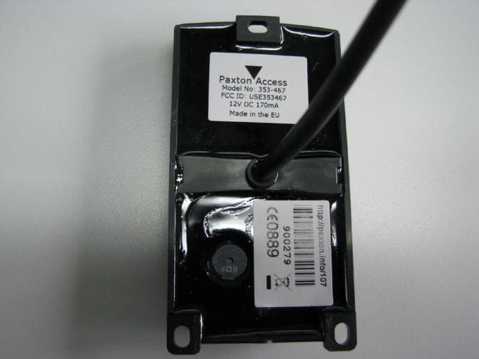
USE353467V2
Nov 25, 2020Secure access proximity reader
Equipment Class
JAB - Part 15 Class B Digital Device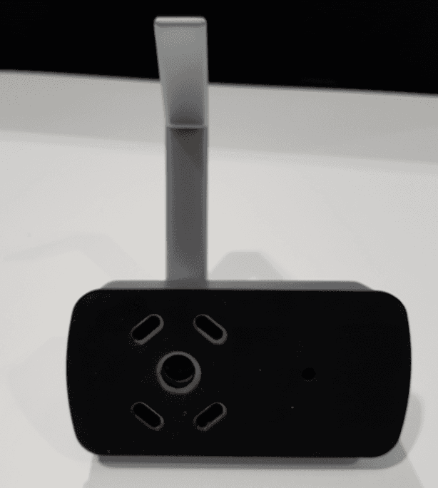
USE900650
Mar 09, 2020Smart electronic lock
Equipment Class
DCD - Part 15 Low Power Transmitter Below 1705 kHz
USE337520
Sep 17, 2015Door entry panel with integral radio transmitter
Equipment Class
DCD - Part 15 Low Power Transmitter Below 1705 kHz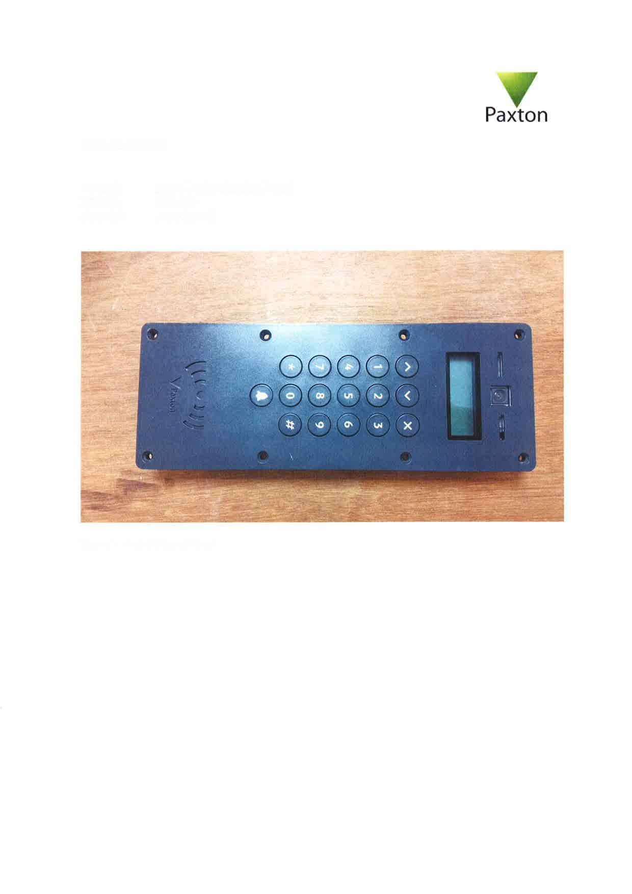
USE337420
Sep 17, 2015Door access system operating on 125kHz and 13.56MHz
Equipment Class
DCD - Part 15 Low Power Transmitter Below 1705 kHz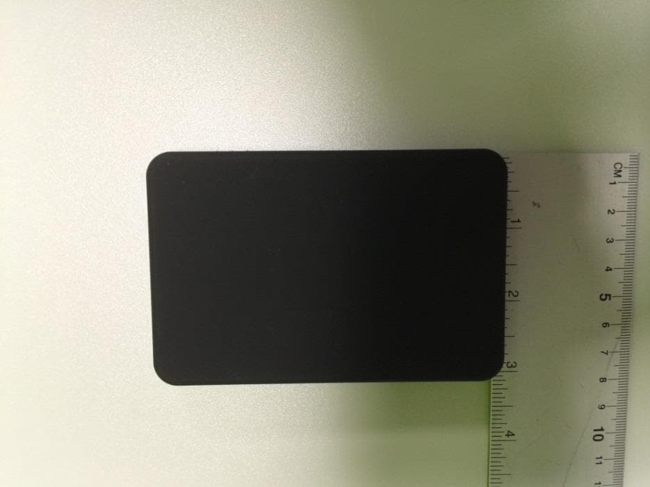
USE010387
Apr 29, 2015net10 desktop reader
Equipment Class
DCD - Part 15 Low Power Transmitter Below 1705 kHz