USE345220PROXIMITY P50M HID READER
Paxton Access Ltd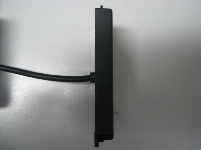
Click to zoom
Application Details
- Equipment Class
- DCD - Part 15 Low Power Transmitter Below 1705 kHz
- Date of Grant
- Jun 20, 2011
- Application Purpose
- Original Equipment
- Date of Application
- Jun 20, 2011
- Equipment Note
- PROXIMITY P50M HID READER
- Frequency Range
- 0.11900000 - 0.11900000
- Company
- Paxton Access Ltd
- Country
- United Kingdom
Documents & Files
Document Text
Text extracted from the exhibit documents filed with the FCC. Open a document above to read the original.
Users Manual
PAGE1 Ins-40158-US PROXIMITY P50M HID TM reader - UL Mounting Technical Support Technical help is available: Monday - Friday from 02:00 AM - 8:00 PM (EST) [email protected] Documentation on all Paxton products can be found on our web site - http://www.paxton-access.com/ Paxton Readers mounted together between readers 12 inches Suitability Security sensitive doors Wet environments 06/08/2011 PAGE2 Cable extensions Wiring Wiring methods shall be in accordance with the National Electrical Code (ANSI/NFPA70), local codes, and the authorities having jurisdiction. UseMax lengthType Reader500 feetBelden 9540, 9538, Alpha 1298C (22AWG) or equivalent Cable Specification Token type and configuration The reader will recognise 125kHz proximity tokens in HID TM format to produce a Wiegand output (26 to 50 bit) or EM4100 tokens to produce an ABA Track2 Clock and Data output. The configuration of the reader is done automatically when the reader detects the first token presented. It will scan the token and match the reader to the format discovered. The reader defaults to HID TM settings after 3 minutes of the initial powering up if no EM4100 token has been presented. If you require EM4100 operation, power cycle the reader and present an EM4100 token within 3 minutes. Once in HID TM or EM4100 mode, the reader will remain in that format. Connection to a control unit reader port +12V DC Red LED Amber LED Green LED Clock/data1 Data/data0 Not required 0V PAGE3 Unit installation / test Following the completed installation of this equipment, no further maintenance or testing is required. It is advisable to ensure that any third party backup power supplies or recovery procedures are checked regularly to ensure that the operation of the Paxton system is not compromised. Maintenance PartDescription 345-220-US PROXIMITY P50M HID TM reader Fitting Kit(5) Cable clips (3) No. 6 x 3 /4 woodscrew - zinc (3) Wall plugs 22mm (1) 8mm x 3mm pan head self tapping screw - zinc (2) Backbox screws Parts List FCC Compliance This device complies with Part 15 of the FCC Rules. Operation is subject to the following two conditions: (1) this device may not cause harmful interference, and (2) this device must accept any interference received, including interference that may cause undesired operation. Changes or modifications not expressly approved by the party responsible for compliance could void the user's authority to operate the equipment. When choosing a location for the reader, ensure that it is at least 12 inches from other readers. This will include readers mounted on the other side of the same wall as the radio signal will cause interference and reduce the read range. Mounting the reader on metal surfaces will reduce the read range. Standard Unit - Drill a hole in the surface for the rear data cable. Secure the unit to the surface with three screws as per fitting diagram on page 1. Suitable screws and fixings are provided for installing the unit to a wall. Ensure the data cable has free access at the rear. A choice of black and white covers are also provided. Hook the required cover over the top of the reader, press home at the bottom and secure with the single fixing screw. The reader will beep and all the LED's should display after powering on the control unit. Presenting a user card to the reader will cause the LED's to briefly change to a single Green or Red LED. Check the following FAQs section for assistance if any problems are encountered. PAGE4 1 - Readers/Keypads not working. Q- Software settings - Confirm that the settings of the reader or keypad are correct. Q- Connections - Check the wiring and integrity of the connectors. If possible, test this reader on the other port. Q- Extended cable - Belden 9538/9540 should be used up to a maximum of 500 feet. Twisted pair alarm cable should Q not be used. To confirm that an extended reader cable is not at fault, wire the reader directly to the port. Q- Supply voltage - Confirm that the voltage is within specification. (see table) Q- User token - Confirm that the user token used for testing is OK by presenting it to a known working reader. Q- Interference - Confirm whether the reader works when tested 'in hand' and not mounted on the wall. Q PROXIMITY readers should not be mounted back to back or close to other RF devices. 2 - Readers / Keypads - Extending cable. QOnly Belden CR9538 / 9540 or a UL equivalent can be used for cable extensions. The maximum run is 500 feet. 3 - Net2 - Using a door reader as a desktop reader. QIt is possible to configure a door reader to operate as a desktop reader: Q1 - Select the doors menu in the left hand Net2 pane. Q2 - Click on the door you wish to change the reader to act as a desktop reader. Q3 - Under the relevant reader tab, change the reader operating mode to 'Desktop Reader'. Q4 - The PC displays 'Would you like to accept desktop reader events from this reader at the PC?' ; click 'Yes' Q Now when you present a blank or existing token to that reader it will allow you to add this new token or edit Q the existing one. NOTE:QRemember to return the operating mode to the original setting once the cards have been read Q or users will not be able to gain access through the reader. Q KP Reader - Ensure that Keypad type is set to 'None', otherwise the Desktop reader option will not be available. 4 - Net2. What to do if a user has no access - Check the reader LED's when a card is shown. Q- No LED's - the reader has no power. Q- No change in display - try the card on a known working reader. If there is still no response, replace the card. Q- Green LED flashing when a card is presented; check relay 1 LED to check for activity and also the lock wiring. Q- Red LED is flashing when a card is presented; check the validity of the user at the PC. Q Check user's access level and ensure they should have access by clicking on Current Validity. Q Check the 'Valid Until' date and confirm this has not expired. Q- Reinstate the ACU from…
Text truncated - open the document above for the full version.
Cover Letter(s)
1(1) Declaration of Authorization: We Name: Paxton Access Ltd Address: Paxton House, Home Farm Road City: Brighton, East Sussex, BN1 9HU Country: UK Declare that: Name: RFI Global Services Ltd. Address: Pavilion A Ashwood Park, Ashwood Way Basingstoke, Hampshire RG23 8BG Is authorized to apply for Certification of the following product: FCC ID: USE345220 Product description: P50M HID Reader Type Designation: 345-220-US On our behalf. This is to certify that Paxton Access Ltd authorises RFI Global Services Limited to act on our behalf for the application of the EUT to RFI Global Services Ltd. Telecommunication Certification Body Section 5301 Certification: We certify that we are not subject to a denial of Federal benefits, that include FCC benefits, pursuant to Section 5301 of the Anti-Drug Abuse Act of 1988, 21 U.S.C. § 862 because of a conviction for possession or distribution of a controlled substance. Date: 13 th June 2011 City: Brighton Name: Brett Glass Signature:
Cover Letter(s)
1(1) Application Examiner Telecommunication Certification Body RFI Global Services Ltd. Pavilion A Ashwood Park Basingstoke Hampshire RG23 8BG United Kingdom Re: Request for confidentiality 13 th June 2011 Applicant: Paxton Access Ltd FCC ID: USE345220 Model Number: 345-220-US To whom it may concern, Permanent Confidentiality Request is hereby submitted by Paxton Access Ltd to withhold permanently from public review certain portions of the application for equipment certification for the referenced FCC identifiers. This request for confidentiality is made pursuant to 47 CFR 0.457(d) and 0.459 of the FCC Rules. In particular, the following sections of the application are to be kept permanently confidential: Circuit Schematic, one file, six pages. Block diagram, one file, one page. Operational/Functional Description, one file, two pages. Parts lists, one file, one page. Rationale for request for confidentiality of all items above. Paxton Access Ltd has invested considerable time and materials in research and development to produce the referenced product. Disclosure of the permanently confidential portions of this application to competitors would not only give them significant competitive advantages in developing similar products, but would also disclose successful implementation of unpublished, leading edge technology developed by us. Sincerely, Conformance Engineer Paxton Access Ltd
External Photos
External Photographs Front view – with cover on Front view – with cover off Bottom view Top view Side view Back view
ID Label/Location Info
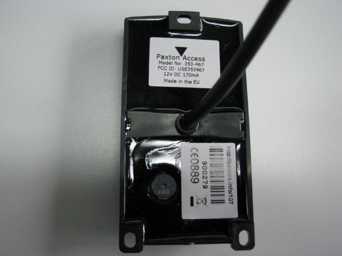
FCC label Information Artwork for 345-220-US – Proximity P50M HID reader Label Make-up Information Label dimensions: 30mm x 20mm and 48mm x 31mm Label material and print ribbon manufacturer: ZEBRA TECHNOLOGIES EUROPE LTD Label materials: Z Xtreme 4000T White with 3200 ribbon OR Z Ultimate 3000T White with 5095 ribbon. UL file number: PGJI2.MH18322 Label Location The label is located on the back of the reader. Company ID (Paxton logo) is also located on the front of the reader.
Internal Photos
Internal Photographs PCB top view PCB bottom view Reader housing/coil sub assembly PCB in housing PCB in housing with cable attached
Test Report
TEST REPORT FROM RFI GLOBAL SERVICES LTD Test of: Proximity mullion HID reader/345-220 FCC ID: USE345220 To: FCC Parts 15.207, 15.209 and 15.215(c) Test Report Serial No: RFI-RPT-RP81268JD05A This Test Report Is Issued Under The Authority Of Chris Guy, Head of Global Approvals: Checked By: Ian Watch Signature: Date of Issue: 14 June 2011 This report is issued in Adobe Acrobat portable document format (PDF). It is only a valid copy of the report if it is being viewed in PDF format with the following security options not allowed: Changing the document, Selecting text and graphics, Adding or changing notes and form fields. This report may not be reproduced other than in full, except with the prior written approval of RFI Global Services Ltd. The results in this report apply only to the sample(s) tested. TEST REPORT SERIAL NO: RFI-RPT-RP81268JD05A VERSION NO. 1.0 ISSUE DATE: 14 JUNE 2011 Page 2 of 17 RFI Global Services Ltd This page has been left intentionally blank. TEST REPORT SERIAL NO: RFI-RPT-RP81268JD05A VERSION NO. 1.0 ISSUE DATE: 14 JUNE 2011 RFI Global Services Ltd Page 3 of 17 Table of Contents 1. Customer Information .................................................................................................................. 4 2. Summary of Testing ..................................................................................................................... 5 2.1. General Information 5 2.2. Summary of Test Results 5 2.3. Methods and Procedures 5 2.4. Deviations from the Test Specification 5 3. Equipment Under Test (EUT) ....................................................................................................... 6 3.1. Identification of Equipment Under Test (EUT) 6 3.2. Description of EUT 6 3.3. Modifications Incorporated in the EUT 6 3.4. Additional Information Related to Testing 6 3.5. Support Equipment 6 4. Operation and Monitoring of the EUT during Testing ............................................................... 7 4.1. Operating Modes 7 4.2. Configuration and Peripherals 7 5. Measurements, Examinations and Derived Results .................................................................. 8 5.1. General Comments 8 5.2. Test Results 9 5.2.1. Transmitter AC Conducted Spurious Emissions 9 5.2.2. Transmitter Fundamental Field Strength 12 5.2.3. Transmitter Radiated Spurious Emissions 13 5.2.4. Transmitter 20 dB Bandwidth 15 6. Measurement Uncertainty .......................................................................................................... 16 Appendix 1. Test Equipment Used ................................................................................................ 17 TEST REPORT SERIAL NO: RFI-RPT-RP81268JD05A VERSION NO. 1.0 ISSUE DATE: 14 JUNE 2011 Page 4 of 17 RFI Global Services Ltd 1. Customer Information Company Name: Paxton Ltd. Address: Paxton House Home Farm Brighton Sussex BN1 9HU United Kingdom TEST REPORT SERIAL NO: RFI-RPT-RP81268JD05A VERSION NO. 1.0 ISSUE DATE: 14 JUNE 2011 RFI Global Services Ltd Page 5 of 17 2. Summary of Testing 2.1. General Information Specification Reference: 47CFR15.207, 47CFR15.209 and 47CFR15.215 Specification Title: Code of Federal Regulations Volume 47 (Telecommunications) 2010: Part 15 Subpart C (Intentional Radiators) - Sections 15.207, 15.209 & 15.215 Site Registration: FCC: 209735 Location of Testing: RFI Global Services Ltd, Wade Road, Basingstoke, Hampshire, RG24 8AH. Test Dates: 08 June to 11 June 2011 2.2. Summary of Test Results FCC Reference (47CFR) Measurement Result Part 15.207 Transmitter AC Conducted Emissions Part 15.209 Transmitter Fundamental Field Strength Part 15.209 Transmitter Radiated Emissions Part 15.215(c) Transmitter 20 dB Bandwidth Key to Results = Complied = Did not comply 2.3. Methods and Procedures Reference: ANSI C63.4 (2009) Title: American National Standard for Methods of Measurement of Radio-Noise Emissions from Low-Voltage Electrical and Electronic Equipment in the Range of 9 kHz to 40 GHz 2.4. Deviations from the Test Specification For the measurements contained within this test report, there were no deviations from, additions to, or exclusions from the test specification identified above. TEST REPORT SERIAL NO: RFI-RPT-RP81268JD05A VERSION NO. 1.0 ISSUE DATE: 14 JUNE 2011 Page 6 of 17 RFI Global Services Ltd 3. Equipment Under Test (EUT) 3.1. Identification of Equipment Under Test (EUT) Brand Name: Paxton Model Name or Number: 345-220 Serial Number: Not stated Hardware Version Number: z-hd02 rev 2 Software Version Number: Not stated FCC ID: USE345220 3.2. Description of EUT The equipment under test was a Proximity mullion HID reader with 119 kHz carrier frequency. 3.3. Modifications Incorporated in the EUT No modifications were applied to the EUT during testing. 3.4. Additional Information Related to Testing Tested Technology: RFID Power Supply Requirement: Nominal 12 V Type of Unit: Transceiver Modulation: AM Transmit Frequency: 119 kHz 3.5. Support Equipment The following support equipment was used to exercise the EUT during testing: Description: Net2 1 door ACU with 2A PSU in plastic cabinet Brand Name: Net2 1 door ACU with 2A PSU in plastic cabinet Model Name or Number: 411-501 Serial Number: Not marked or stated TEST REPORT SERIAL NO: RFI-RPT-RP81268JD05A VERSION NO. 1.0 ISSUE DATE: 14 JUNE 2011 RFI Global Services Ltd Page 7 of 17 4. Operation and Monitoring of the EUT during Testing 4.1. Operating Modes The EUT was tested in the following operating mode(s): • Constantly transceiving. 4.2. Configuration and Peripherals The EUT was tested in the following configuration(s): • Connected via a 5 metre multicore cable to a Net2 ACU reader port contained inside a 2A PSU cabinet. Net2 1 door ACU was connected to a 120 VAC 50 Hz supply for all tests TEST REPORT SERIAL NO: RFI-RPT-RP81268JD05A VERSION NO. 1.0 ISSUE DATE: 14 JUNE 2011 Page 8 of 17 RFI Global Services Ltd 5. Measurements, Examinations and Derived Results 5.1. General Comments Measurement unce…
Text truncated - open the document above for the full version.
Contact Information
Applicant
Brett David Glass(Mr)
Test Firm
UL VS LtdDarren Rust
Technical Specifications
| # | Rule Parts | Frequency Range | Power Output |
|---|---|---|---|
| 1 | 15C | 0.119 MHz - 0.119 MHz | - |
Other Applications from Paxton Access Ltd
USE353467V2
Nov 25, 2020Secure access proximity reader
Equipment Class
JAB - Part 15 Class B Digital Device
USE900650
Mar 09, 2020Smart electronic lock
Equipment Class
DCD - Part 15 Low Power Transmitter Below 1705 kHz
USE337520
Sep 17, 2015Door entry panel with integral radio transmitter
Equipment Class
DCD - Part 15 Low Power Transmitter Below 1705 kHz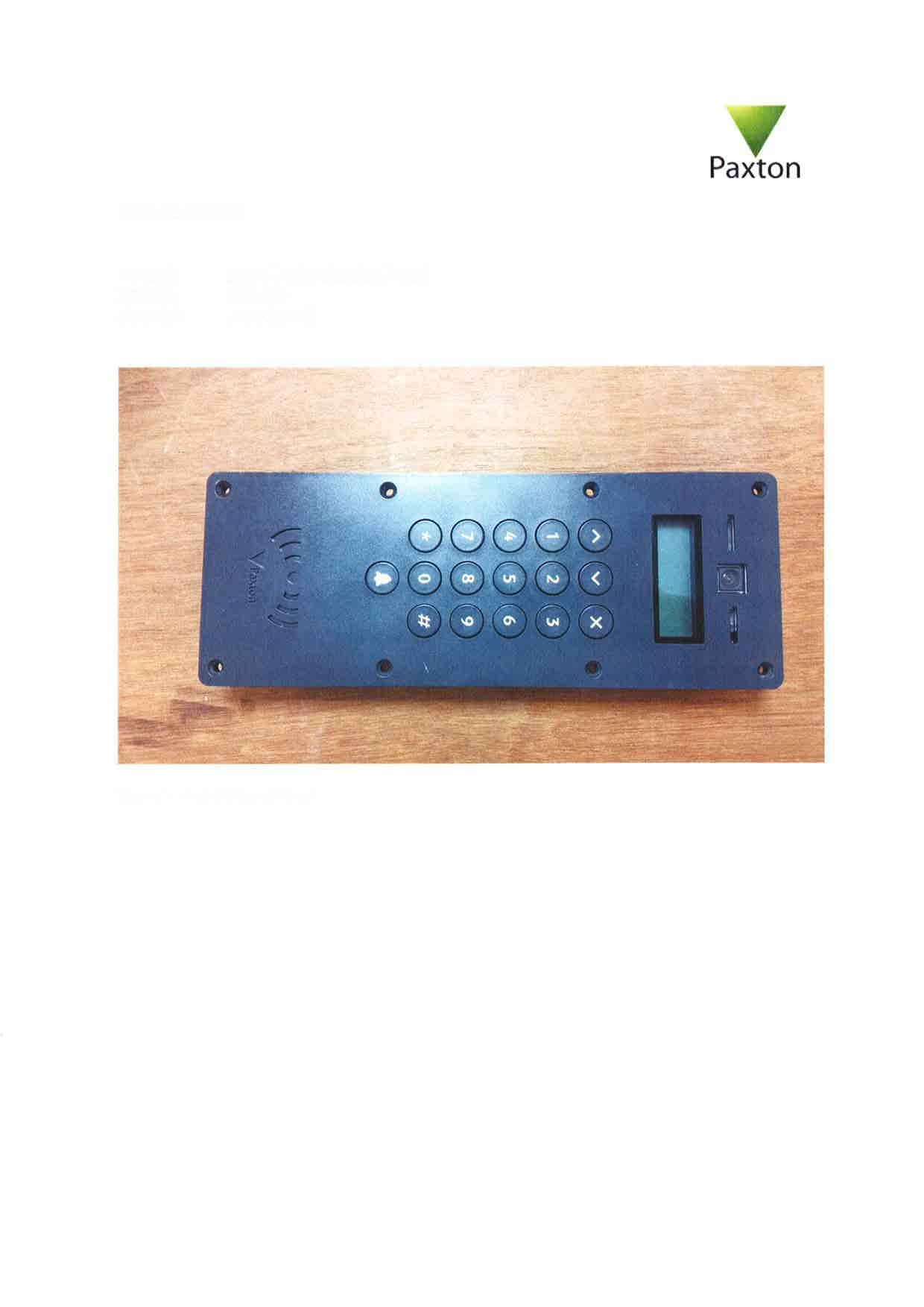
USE337420
Sep 17, 2015Door access system operating on 125kHz and 13.56MHz
Equipment Class
DCD - Part 15 Low Power Transmitter Below 1705 kHz
USE010387
Apr 29, 2015net10 desktop reader
Equipment Class
DCD - Part 15 Low Power Transmitter Below 1705 kHz