USE390135Proximity Panel Mount Reader
Paxton Access Ltd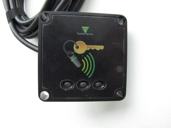
Click to zoom
Application Details
- Equipment Class
- DCD - Part 15 Low Power Transmitter Below 1705 kHz
- Date of Grant
- May 20, 2012
- Application Purpose
- Original Equipment
- Date of Application
- May 17, 2012
- Equipment Note
- Proximity Panel Mount Reader
- Frequency Range
- 0.12500000 - 0.12500000
- Company
- Paxton Access Ltd
- Country
- United Kingdom
Documents & Files
Document Text
Text extracted from the exhibit documents filed with the FCC. Open a document above to read the original.
Users Manual
PAGE1 Ins-40049-US PROXIMITY metal reader - UL Mounting This reader is designed to read Paxton Tokens (Hitag2) and EM4100 tokens. It will provide Clock and Data output for Paxton (Net2 / Switch2). Mounted on metal surface Suitability Security sensitive doors Wet environments Technical Support Technical help is available: Monday - Friday from 02:00 AM - 8:00 PM (EST) [email protected] Documentation on all Paxton products can be found on our web site - http://www.paxton-access.com/ Readers mounted together Paxton 03/15/2012 For instructions in alternative languages - http://paxton.info/1000 PAGE2 Cable extensions Red 12v dc Brown Orange Green Yellow Blue Mauve Black/White Brown Yellow Reader 1 Orange Keypad 1 +12v 0v N.C. N.O. Com N.C. N.O. Com Alarm Output 0v Contact 0v Exit 0v Tamper PSU Rx Tx Relay 1 Relay 2 Exit Contact Tamper PSU OK 5v 12v Red Brown Orange Green Yellow Blue Mauve Black/White Brown Yellow Orange Reader 2 Keypad 2 Power Relay 1 Relay 2 Inputs Network CAT5 cable coding White/Green Green White/Orange Orange 1 2 3 4 Screen or spare cores from network cable CAUTION: for 12v d.c. readers only. For correct connection of old 5v readers, refer to instructions. Serial number 241821 Test ID: 012345678901 z-1440 3 2 4 8 9 8 0 0 0 0 0 4 x R Green White/Green 1 Screen or spare cores from network cable White/O r ang e 3 O r ang e 4 K 1 r e d a e R d a p y e 1 12V Alarm Output R l e a y 2 N.C. N. O . Com N.C. N. O . Com 0 V 0V Exit 0 V PSU 0V Contact T ampe r R l e a y 1 V 2 1 V 5 K O T e p m a r t c a t n o C t i x E R l e a y 1 x T U S P K eypad 2 Reader 2 s t u p n I P e w o r R l e a y 2 C A n i d o c e l b a c 5 T g k r o w t e N +V out Red LED Amber LED Green LED Data/D0 Clock/D1 Media Detect 0V out Data Load Clock t u o V + D E L d e R D E L r e b m A D E L n e e r G 0 D / a t a D 1 D / k c o l C t c e t e D a i d e M t u o V 0 a t a D d a o L k c o l C Net2 2 Wiring UseMax lengthType Reader / Keypad500 feet8 core shielded, Beldon 9538, Alpha 1298C (22AWG) or equivalent Cable Specification Part numberDescription 390-747-USPROXIMITY metal reader Options Net2 control unit Switch2 control unit Red 12V Brown Orange Green Yellow Blue Mauve Exit Contact Black Card reader or keypad 12v 0v N.C. N.O. Com Bell Power Door relay Alarm witch 2 S Control unit Inputs CAUTION: For 12V d.c. readers only. For correct connection of old readers, refer to instructions. Card reader or keypad Inputs Door relay Power Alarm Bell 12V 0V N.C. N.O. COM CAUTION: For 12Vd.c. readers only. For correct connection of old readers, refer to instructions. Contact Exit Switch2 12V Red LED Amber LED Green LED Data/D0 Clock/D1 Media Detect 0V PAGE3 Reader installation and test Following the completed installation of this equipment, no further maintenance or testing is required. It is advisable to ensure that any third party backup power supplies or recovery procedures are checked regularly to ensure that the operation of the Paxton system is not compromised. Maintenance FCC Compliance This device complies with Part 15 of the FCC Rules. Operation is subject to the following two conditions: (1) this device may not cause harmful interference, and (2) this device must accept any interference received, including interference that may cause undesired operation. Changes or modifications not expressly approved by the party responsible for compliance could void the user's authority to operate the equipment. Drill a hole in the surface for the rear data cable. Secure the mounting plate to the surface with four screws as per fitting diagram on page 1. Suitable screws and fixings are provided for fitting the plate to a wall. Mount the reader on its backplate and secure with the security screws using the Allen key supplied. Ensure the data cable has free access at the rear. The reader will bleep and all the LEDS should display after powering on the control unit. Presenting a user card to the reader will cause the LEDs to briefly change to a single Green or Red LED. Check the following FAQs section for assistance if any problems are encountered. Parts list Part numberDescription Fitting Kit fk1-0584 off - M5x20 Security button socket pin head machine screw 4 off - No8 x 1 1 /2in pozi round woodscrew - zinc 4 off - Wall plugs 35mm, red 1 off - 3mm socket pin head Allen key The use of any add-on, expansion, memory or other module manufactured or supplied by the manufacturer's representative will invalidate the CAN/ULC-S319 certification. For CAN/ULC-S319 installations, terminals, leads and wiring methods must comply with CSA, C22.1, Canadian electrical code, Part 1, safety standards for electrical installations. Product compliance and limitations To comply as a UL listed installation, the following conditions must apply:- Server based functions (Antipassback, Time and Attendance, etc) have not been evaluated by UL and cannot be used for UL 294 installations. The use of Wiegand readers and the configuration software has not been evaluated by 'UL' Wiring: - Where an equivalent cable / wire is used it must be ' UL Listed ' All interconnecting devices must be UL Listed. Wiring methods shall be in accordance with the National Electrical Code (ANSI/NFPA70), local codes, and the authorities having jurisdiction. This device complies with Industry Canada licence-exempt RSS standard(s). Operation is subject to the following two conditions: (1) this device may not cause interference, and (2) this device must accept any interference, including interference that may cause undesired operation of the device. PAGE4 -35 °C ( -31 °F ) +66 °C ( + 151 °F ) WaterproofIPX7 10 feet 12V DC 110 mA 125 kHz 600 μs 2 inch1 1 /2 inch 3 inch3 inch 1 inch Voltage Clock and data bit period Carrier frequency Specifications Operating temperatures - all items Electrical Environment Dimensions Min Max Width Height Depth Current Cable length Read Range Token Keyfob Hands Free Token Here is the list of topics about this product that receive the …
Text truncated - open the document above for the full version.
Users Manual
PAGE1 Ins-40078-US PROXIMITY panel mount reader - UL Mounting Compatible with hands free tokens Suitability Security sensitive doors Wet environments Technical Support Technical help is available: Monday - Friday from 02:00 AM - 8:00 PM (EST) [email protected] Documentation on all Paxton products can be found on our web site - http://www.paxton-access.com/ This reader is designed to read Paxton Tokens (Hitag2) and EM4100 tokens. It will provide Clock and Data output for Paxton (Net2 / Switch2). Readers mounted together between readers 12 inches Paxton 03/14/2012 For instructions in alternative languages - http://paxton.info/1000 PAGE2 Cable extensions Red 12v dc Brown Orange Green Yellow Blue Mauve Black/White Brown Yellow Reader 1 Orange Keypad 1 +12v 0v N.C. N.O. Com N.C. N.O. Com Alarm Output 0v Contact 0v Exit 0v Tamper PSU Rx Tx Relay 1 Relay 2 Exit Contact Tamper PSU OK 5v 12v Red Brown Orange Green Yellow Blue Mauve Black/White Brown Yellow Orange Reader 2 Keypad 2 Power Relay 1 Relay 2 Inputs Network CAT5 cable coding White/Green Green White/Orange Orange 1 2 3 4 Screen or spare cores from network cable CAUTION: for 12v d.c. readers only. For correct connection of old 5v readers, refer to instructions. Serial number 241821 Test ID: 012345678901 z-1440 3 2 4 8 9 8 0 0 0 0 0 4 x R Green White/Green 1 Screen or spare cores from network cable White/O r ang e 3 O r ang e 4 K 1 r e d a e R d a p y e 1 12V Alarm Output R l e a y 2 N.C. N. O . Com N.C. N. O . Com 0 V 0V Exit 0 V PSU 0V Contact T ampe r R l e a y 1 V 2 1 V 5 K O T e p m a r t c a t n o C t i x E R l e a y 1 x T U S P K eypad 2 Reader 2 s t u p n I P e w o r R l e a y 2 C A n i d o c e l b a c 5 T g k r o w t e N +V out Red LED Amber LED Green LED Data/D0 Clock/D1 Media Detect 0V out Data Load Clock t u o V + D E L d e R D E L r e b m A D E L n e e r G 0 D / a t a D 1 D / k c o l C t c e t e D a i d e M t u o V 0 a t a D d a o L k c o l C Net2 2 Wiring UseMax lengthType Reader / Keypad500 feet8 core, shielded - Beldon 9538, Alpha 1298C (22AWG) or equivalent Cable Specification Part numberDescription 390-135-USPROXIMITY panel mount reader Options Net2 control unit Switch2 control unit Red 12V Brown Orange Green Yellow Blue Mauve Exit Contact Black Card reader or keypad 12v 0v N.C. N.O. Com Bell Power Door relay Alarm witch 2 S Control unit Inputs CAUTION: For 12V d.c. readers only. For correct connection of old readers, refer to instructions. Card reader or keypad Inputs Door relay Power Alarm Bell 12V 0V N.C. N.O. COM CAUTION: For 12Vd.c. readers only. For correct connection of old readers, refer to instructions. Contact Exit Switch2 12V Red LED Amber LED Green LED Data/D0 Clock/D1 Media Detect 0V PAGE3 Following the completed installation of this equipment, no further maintenance or testing is required. It is advisable to ensure that any third party backup power supplies or recovery procedures are checked regularly to ensure that the operation of the Paxton system is not compromised. Maintenance Description Not requiredReader fits to studs on customer facia Parts Kit Reader installation and test The panel mount reader is designed to fit into a door entry panel. It fits behind a reader aperture of industry standard size (40 mm x 40 mm) and is supplied with a polycarbonate window to match. See front page for fitting detail. Holes are provided in each corner to fit over 4 posts set in a 49 mm square formation. Fixings are not provided as they will normally be supplied with the panel. When powered up, the reader will beep and all the LED's should display. Presenting a user card to the reader will cause the LED's to briefly change to a single Green or Red LED. Check the following FAQs section for assistance if any problems are encountered. FCC Compliance This device complies with Part 15 of the FCC Rules. Operation is subject to the following two conditions: (1) this device may not cause harmful interference, and (2) this device must accept any interference received, including interference that may cause undesired operation. Changes or modifications not expressly approved by the party responsible for compliance could void the user's authority to operate the equipment. The use of any add-on, expansion, memory or other module manufactured or supplied by the manufacturer's representative will invalidate the CAN/ULC-S319 certification. For CAN/ULC-S319 installations, terminals, leads and wiring methods must comply with CSA, C22.1, Canadian electrical code, Part 1, safety standards for electrical installations. Product compliance and limitations To comply as a UL listed installation, the following conditions must apply:- Server based functions (Antipassback, Time and Attendance, etc) have not been evaluated by UL and cannot be used for UL 294 installations. The use of Wiegand readers and the configuration software has not been evaluated by 'UL' Wiring: - Where an equivalent cable / wire is used it must be ' UL Listed ' All interconnecting devices must be UL Listed. Wiring methods shall be in accordance with the National Electrical Code (ANSI/NFPA70), local codes, and the authorities having jurisdiction. This device complies with Industry Canada licence-exempt RSS standard(s). Operation is subject to the following two conditions: (1) this device may not cause interference, and (2) this device must accept any interference, including interference that may cause undesired operation of the device. PAGE4 12V DC 150 mA 125 kHz 600 μs -35 °C ( -31 °F ) +66 °C ( + 151 °F ) IPX7 10 feet 2”1 1 /2” 2 1 /4 ”2 1 /4 ” 11 /16 ” 40 mm (1 19 /32”)40 mm (1 19 /32”) - 49 mm (1 30 /32”)49 mm (1 30 /32”) Here is the list of topics about this product that receive the most technical support inquiries. We list them here to help you speed up the installation and trouble shooting process. Technical Help 1 - Readers/Keypads not working. Q- Software settings - Confirm that the settings of the reader or keypad are correct. Q- Connections…
Text truncated - open the document above for the full version.
Cover Letter(s)
1 Identification List Item 1: a) Model Number: 390-135-US b) IC ID: 10217A-390135 c) Description: Proximity panel mount reader d) Instruction document number: ins-40078-US Item 2: a) Model Number: 390-747-US b) Description: Proximity metal reader, satin chrome c) Instruction document number: ins-40049-US d) Product similarity: Same reader module as 390-135-US above, but has an additional outer metal housing. Item 3: a) Model Number: 390-727-US b) Description: Proximity metal reader, chrome c) Instruction document number: ins-40049-US d) Product similarity: Same reader module as 390-747-US above, but has a different coat finish. 2 Item 4: a) Model Number: 390-737-US b) Description: Proximity metal reader, brass c) Instruction document number: ins-40049-US d) Product similarity: Same reader module as 390-747-US above, but has a different coat finish.
Cover Letter(s)
Paxton Access Ltd. • Paxton House • Home Farm Road • Brighton • East Sussex • BN1 9HU • UK Tel: 0845 838 1716 • Fax 01273 811089 • Web http://www.paxton-access.co.uk Registered No:1879474 (England) • Registered office: As above Request for Confidentiality Date: 04-27-2012 Subject: Confidentiality Request for: FCC ID: USE390135 IC: 10217A-390135 Pursuant to FCC 47 CRF 0.457(d) and 0.459 and IC RSP-100, Section 10, the applicant requests that a part of the subject FCC application be held confidential. Type of Confidentiality Requested Exhibit Short Term Permanent Block Diagrams Short Term External Photos Short Term Permanent* 1 Internal Photos Short Term Permanent Operation Description/Theory of Operation Short Term Permanent Parts List & Placement/BOM Short Term Permanent Tune-Up Procedure Short Term Permanent Schematics Short Term Test Setup Photos Short Term Permanent* User’s Manual Paxton Access has spent substantial effort in developing this product and it is one of the first of its kind in industry. Having the subject information easily available to "competition" would negate the advantage they have achieved by developing this product. Not protecting the details of the design will result in financial hardship. Permanent Confidentiality: The applicant requests the exhibits listed above as permanently confidential be permanently withheld from public review due to materials that contain trade secrets and proprietary information not customarily released to the public. NOTE for Industry Canada Applications: The applicant understands that until such time that IC distinguishes between Short Term and Permanent Confidentiality, either type of marked exhibit above will simply be marked Confidential when submitted to IC. Sincerely, By: Brett Glass Conformance Engineer
External Photos
External Photographs Side view Front view Back view
ID Label/Location Info
Label artworks 1. Artwork for 390-747-US - PROXIMITY metal reader 2. Artwork for 390-727-US - PROXIMITY metal reader, chrome 3. Artwork for 390-737-US - PROXIMITY metal reader, brass 4. Artwork for 390-135-US - PROXIMITY panel mount reader Label Make-up Information Label dimensions: 48mm x 31mm Label material and print ribbon manufacturer: ZEBRA TECHNOLOGIES EUROPE LTD Label materials: Z Xtreme 4000T White with 3200 ribbon OR Z Ultimate 3000T White with 5095 ribbon. UL file number: PGJI2.MH18322 Label Location Located on the back of the reader.
Internal Photos
Internal Photographs 1. Internal Construction Loop antenna wound around plastic coil former Antenna/coil former attachment to circuit board. Circuit board and coil former placed inside reader housing. Securement of circuit board and cable clamp to reader housing with five screws. 2. Circuit board layout and component placement Unpopulated PCB Populated PCB Circuit board top view Unpopulated PCB Populated PCB Circuit board bottom view
Test Report
TEST REPORT FROM RFI GLOBAL SERVICES LTD Test of: Paxton Ltd, 390-135-US To: 47CFR15.207, 47CFR15.209, 47CFR 15.215 ( c ), RSS-Gen Issue 3 December 2010 and RSS-210 Issue 8 December 2010 Test Report Serial No: RFI-EMC-RP85596JD11A V3.0 Version 3.0 supersedes all previous versions This test report is issued under the authority of John Newell, Group Quality Manager: Checked By: Gareth Bragg Signature: Date of Issue: 03 May 2012 This report is issued in portable document format (PDF). It is only a valid copy of the report if it is being viewed in PDF format with the following security options not allowed: Changing the document, Selecting text and graphics, Adding or changing notes and form fields. This report may not be reproduced other than in full, except with the prior written approval of RFI Global Services Ltd. The results in this report apply only to the sample(s) tested. TEST REPORT SERIAL NO: RFI-EMC-RP85596JD11A V3.0 VERSION: 3.0 ISSUE DATE: 03 MAY 2012 Page 2 of 37 RFI Global Services Ltd. This page has been left intentionally blank. TEST REPORT SERIAL NO: RFI-EMC-RP85596JD11A V3.0 VERSION: 3.0 ISSUE DATE: 03 MAY 2012 RFI Global Services Ltd. Page 3 of 37 TABLE OF CONTENTS 1. Customer Details .............................................................................................................. 5 2. Summary of Testing ......................................................................................................... 6 3. Equipment under Test (EUT) ........................................................................................... 7 4. Support Equipment ........................................................................................................... 8 5. Monitoring Performance .................................................................................................. 9 6. Measurement Uncertainty .............................................................................................. 10 7. Measurements, Examinations and Derived Results .................................................... 11 8. Photographs of EUT ....................................................................................................... 22 9. Graphical Test Results ................................................................................................... 26 10. Test Configuration Drawing ......................................................................................... 35 11. Report Revision History ............................................................................................... 37 TEST REPORT SERIAL NO: RFI-EMC-RP85596JD11A V3.0 VERSION: 3.0 ISSUE DATE: 03 MAY 2012 Page 4 of 37 RFI Global Services Ltd. This page has been intentionally left blank. TEST REPORT SERIAL NO: RFI-EMC-RP85596JD11A V3.0 VERSION: 3.0 ISSUE DATE: 03 MAY 2012 RFI Global Services Ltd. Page 5 of 37 1. CUSTOMER DETAILS Company Name: Paxton Ltd Address: Paxton House Home Farm Brighton Sussex BN1 9HU United Kingdom TEST REPORT SERIAL NO: RFI-EMC-RP85596JD11A V3.0 VERSION: 3.0 ISSUE DATE: 03 MAY 2012 Page 6 of 37 RFI Global Services Ltd. 2. SUMMARY OF TESTING 2.1. Test Specification Reference: 47CFR15.207, 47CFR15.209 and 47CFR15.215 ( c ) Title: Code of Federal Regulations Volume 47 (Telecommunications) 2010: Part 15 Subpart C (Intentional Radiators) – Sections 15.207, 15.209 and 15.215 ( c ) Reference: RSS-Gen Issue 3 December 2010 Title: General Requirements and Information for the Certification of Radio Apparatus Reference: RSS-210 Issue 8 December 2010 Title: Licence-exempt Radio Apparatus ( All Frequency Bands ): Category I Equipment Site Registration: FCC: 209735 Industry Canada: 3245B-2 2.2. Summary of Test Results FCC Reference IC Reference Measurement Type Applicability Result N/A RSS-Gen 7.2.4 Transmitter 99% Emission Bandwidth YES 15.209 RSS-Gen 4.9/7.2.5 Transmitter Fundamental Field Strength YES 15.109 RSS-Gen 4.9/7.2.5 Transmitter Radiated Emissions YES 15.107 RSS-Gen 4.6.1 Transmitter AC Conducted Emissions YES 15.215 N/A Transmitter 20 dB Bandwidth YES KEY: = Complied = Did not comply 2.3. Location of Testing All the measurements described in this report were performed at the premises of RFI Global Services Ltd, Unit 3 Horizon, Wade Road, Kingsland Business Park, Basingstoke, Hampshire RG24 8AH. 2.4. Deviations from the Test Specification For the measurements contained within this test report, there were no deviations from, additions to, or exclusions from the test specification identified above, nor from the requirements defined in the basic standards called up within it. TEST REPORT SERIAL NO: RFI-EMC-RP85596JD11A V3.0 VERSION: 3.0 ISSUE DATE: 03 MAY 2012 RFI Global Services Ltd. Page 7 of 37 3. EQUIPMENT UNDER TEST (EUT) 3.1. Description of EUT The EUT was a proximity reader. 3.2. Identification of Equipment under Test (EUT) ID# Description Brand Name Model No Serial No E1 Proximity Reader Paxton Ltd 390-135-US 1153065 3.3. Port Identification Port Description Type P1 Enclosure - P2 Power / Data 8-core 3.4. Operating Modes Mode Reference Definition Transmit The EUT was continuously transmitting at 125 kHz and all LEDS were illuminated 3.5.Radio characteristics Transmit Frequency (kHz): 125 Rated Output Power (mW): < 20 3.6. Configuration and Peripherals Description: Please refer to the Test Configuration and Photograph section for schematic drawing(s) and/or photograph(s) of the test configuration(s) employed in the course of testing. 3.7. Modifications NOTE: No modifications were made to the EUT during the course of testing. 3.8. Additional Information Related to Testing Equipment Category: Proximity Reader Intended Operating Environment: Residential / Commercial Cycle Time: < 1 s Power Supply Requirement(s): 12 VDC Weight: < 100 g Dimensions: 55 x 55 x 13 mm Hardware Version Number: z-umprp rev 1, ppc-umpr rev D Software Version Number: Not Applicable Highest Internally Generated Operating Frequency: 125 kHz Industry Canada Certification Numbe…
Text truncated - open the document above for the full version.
Test Setup Photos
TEST SETUP PHOTOGRAPHS EXHIBIT Product Description: Proximity Panel Mount Reader Model Number: 390-135-US FCC ID: USE390135 IC ID: 10217A-390135 TEST REPORT SERIAL NO: RFI-EMC-RP85596JD11A VERSION: 1.0 ISSUE DATE: 20 MARCH 2012 Page 22 of 34 RFI Global Services Ltd. PHT\85596JD11\001 - Test Configuration Photograph - Radiated Emissions 001 TEST REPORT SERIAL NO: RFI-EMC-RP85596JD11A VERSION: 1.0 ISSUE DATE: 20 MARCH 2012 RFI Global Services Ltd. Page 23 of 34 PHT\85596JD11\002 - Test Configuration Photograph - Radiated Emissions 002 TEST REPORT SERIAL NO: RFI-EMC-RP85596JD11A VERSION: 1.0 ISSUE DATE: 20 MARCH 2012 Page 24 of 34 RFI Global Services Ltd. PHT\85596JD11\003 - Test Configuration Photograph - Conducted Emissions
Contact Information
Applicant
Brett David Glass(Mr)
Test Firm
UL VS LtdDarren Rust
Technical Specifications
| # | Rule Parts | Frequency Range | Power Output |
|---|---|---|---|
| 1 | 15C | 0.125 MHz - 0.125 MHz | - |
Other Applications from Paxton Access Ltd
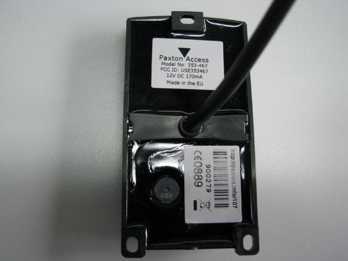
USE353467V2
Nov 25, 2020Secure access proximity reader
Equipment Class
JAB - Part 15 Class B Digital Device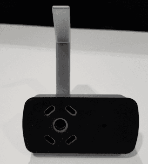
USE900650
Mar 09, 2020Smart electronic lock
Equipment Class
DCD - Part 15 Low Power Transmitter Below 1705 kHz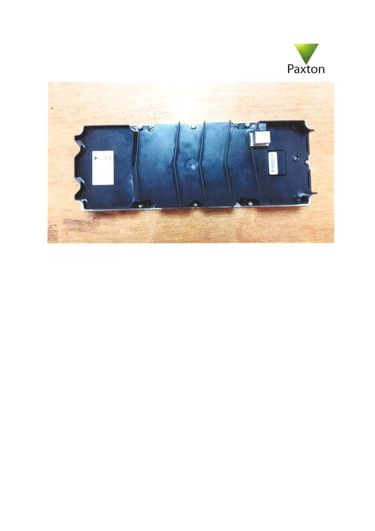
USE337520
Sep 17, 2015Door entry panel with integral radio transmitter
Equipment Class
DCD - Part 15 Low Power Transmitter Below 1705 kHz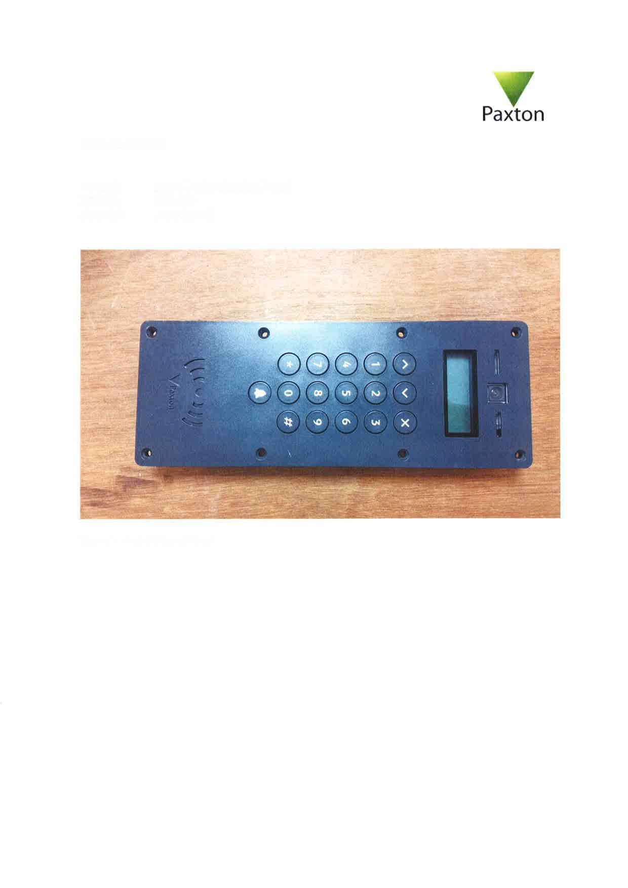
USE337420
Sep 17, 2015Door access system operating on 125kHz and 13.56MHz
Equipment Class
DCD - Part 15 Low Power Transmitter Below 1705 kHz
USE010387
Apr 29, 2015net10 desktop reader
Equipment Class
DCD - Part 15 Low Power Transmitter Below 1705 kHz