USE568855568-855-US Proximity Vandal Proof Reader
Paxton Access Ltd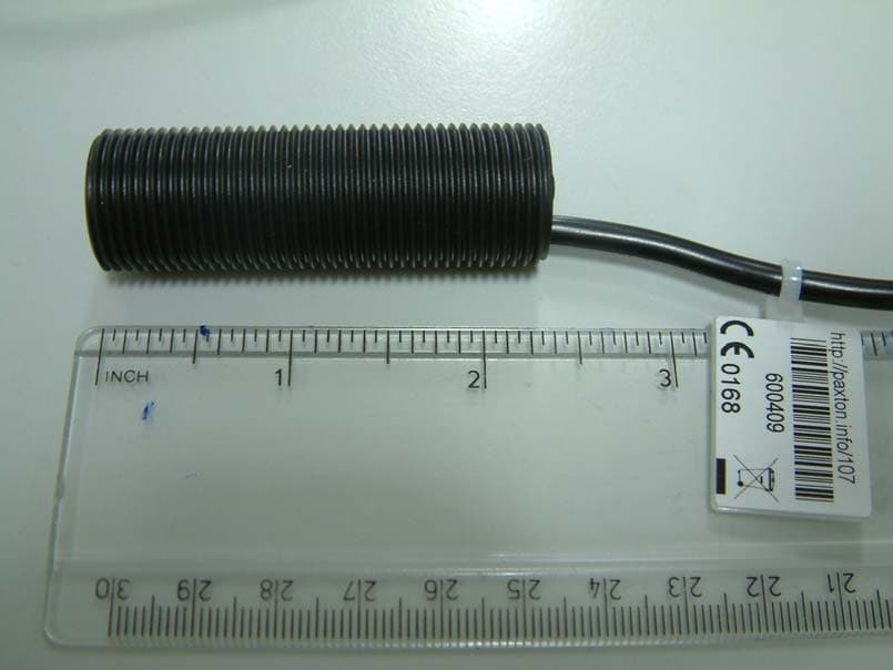
Click to zoom
Application Details
- Equipment Class
- DCD - Part 15 Low Power Transmitter Below 1705 kHz
- Date of Grant
- Feb 01, 2007
- Application Purpose
- Original Equipment
- Date of Application
- Jan 24, 2007
- Equipment Note
- 568-855-US Proximity Vandal Proof Reader
- Frequency Range
- 0.12500000 - 0.12500000
- Company
- Paxton Access Ltd
- Country
- United Kingdom
Documents & Files
Document Text
Text extracted from the exhibit documents filed with the FCC. Open a document above to read the original.
Users Manual
Technical Support Technical help is available Monday - Friday from 07:00 - 19:00. Other documentation on Net2 can be found on our web site - http://www.paxton-access.co.uk/ +44(0)845 [email protected] ������������� Ins-138-US PROXIMITY vandal proof reader Suitability Fitting Open hole - medium vandal resistance Blind hole - very high vandal resistance Cement plug - high vandal resistance 28/11/2006 Security sensitive doorsWet environments Mounted on metal surface Readers mounted together between readers 500mm Wiring Cable extensions ���������� ����� ������ ����� ������ ���� ����� ����������� ����� ������ �������� ������ �������� ���� �� ���� ���� ��� ���� ���� ��� ������������ �� ������� �� ���� �� ������ ��� �� �� ������� ������� ���� ������� ������ ��� �� �� ��� ��� ����� ������ ����� ������ ���� ����� ����������� ����� ������ ������ �������� �������� ����� ������� ������� ������ ������� ����������������� ����������� ����� ������������ ������ � � � � ��������������������� ������������������ ��������������������������������������������������������������������������������������������������� Serial number241821Test ID: 012345678901z-1440 � � � � � � � � � � � � ��� ����� ������ ����� ������ ���� ����� ����������� ����� ������ �������� ������ �������� ���� �� ���� ���� ��� ���� ���� ��� ������������ �� ������� �� ���� �� ������ ��� �� �� ������� ������� ���� ������� ������ ��� �� �� ��� ��� ����� ������ ����� ������ ���� ����� ����������� ����� ������ ������ �������� �������� ����� ������� ������� ������ ������� ����������������� ����������� ����� ������������ ������ � � � � ��������������������� ������������������ Serial number241821Test ID: 012345678901z-1440 � � � � � � � � � � � � Readers can be extended using Belden CR9540 10-core overall screened cable. The maximum cable length between reader and control unit is 100m. ������� ����� ������ ����� ������ ���� ����� ���� ������� ����� ��������������������� ���� ��� ���� ���� ��� ���� ����� ���������� ����� witch 2 S ������� ���� ������ CAUTION����������������������� ������������������������������������ ������������������������������� ��� ����� ������ ����� ������ ���� ����� ���� ������� ����� ��������������������� ���� ��� ���� ���� ��� ���� ����� ���������� ����� witch 2 S ������� ���� ������ FCC Compliance This device complies with Part 15 of the FCC Rules. Operation is subject to the following two conditions: (1) this device may not cause harmful interference, and (2) this device must accept any interference received, including interference that may cause undesired operation. Changes or modifications not expressly approved by the party responsible for compliance could void the user’s authority to operate the equipment. Specifications Vandal proof reader - tube 19 dia 60 d mm Vandal proof reader - cover cap 48 h 30 w mm Panel mounting studs - position (in a square around the center of the reader) 49mm Electrical Operating voltage 91214V d.c. Current consumption 50 min 120 max mA Carrier frequency 125kHz Clock & data bit period 600us Product specific information Water resistance IPX7 Vandal resistance Very high Max read range: cards 100mm Max read range: keyfobs 55mm Security High Width 30mm Height 48mm Depth 9mm Diameter 19mm Length 59mm Cable type - for extension Belden 8 core CR9538 Max cable extension from control unit 100m Cable length 5m Token reads Not limited
Cover Letter(s)
1(1) Attention: Application Examiner Re: Request for confidentiality Applicant: Paxton Access Ltd FCC ID: USE568855 29 th December 2006 To whom it may concern, Permanent Confidentiality Request is hereby submitted by Paxton Access Ltd to withhold permanently from public review certain portions of the application for equipment certification for the referenced FCC identifiers. This request for confidentiality is made pursuant to 47 CFR 0.457(d) and 0.459 of the FCC Rules. In particular, the following sections of the application are to be kept permanently confidential: 1. Schematics 2. Detailed Block diagrams 3. Detailed Operational/Functional Description 4. Internal Photos Rationale for request for confidentiality for items 1,2, and 3: Paxton Access Ltd has invested considerable time and materials in research and development to produce the referenced product. Disclosure of the permanently confidential portions of this application to competitors would not only give them significant competitive advantages in developing similar products, but would also disclose successful implementation of unpublished, leading edge technology developed by us. Rationale for request for confidentiality for item 4: The device is permanently sealed or potted, and any attempt to open it would result in destruction of the device. Sincerely, Quality Manager Paxton Access Ltd
Cover Letter(s)
From: EASTECH [[email protected]] Sent: Wednesday, January 24, 2007 9:45 AM To: Roland Gubisch ES-BOX Subject: RE: Holding internal photos permanently confidential Hello Roland, TCB's can mark internal photos confidential. A justification must be provided in the confidentiality request letter. The request below has been approved by the FCC before for a similar device. You should submit a copy of this inquiry in the filing Thanks From: Roland Gubisch ES-BOX [mailto:[email protected]] Sent: Tuesday, January 16, 2007 12:04 PM To: EASTECH Subject: Holding internal photos permanently confidential Dear Sir or Madam, We are holding a TCB application for a commercial 125 kHz RFID reader for secure entry control. The device is potted completely, and the applicant’s request for confidentiality notes that any attempt to open it would destroy the device. The applicant is requesting permanent confidentiality for the internal photos, in addition to the more customary exhibits such as schematics. We believe that this request is reasonable and wish to comply. Please advise. Thank you, Roland Gubisch Intertek
Cover Letter(s)
From: Roland Gubisch ES-BOX Sent: Tuesday, January 02, 2007 9:41 AM To: 'Brett Glass' Cc: Terre Wolak ES-ATL; David Legge ES-Lhd; Lorna Airlie ES-Lhd; David Feasey ES-Lhd Subject: RE: Certification review of Proximity P50 Reader FCC ID: USE353110 Attachments: Modulation and restricted band.pdf; 47cfr15-2005.pdf; FCC DoC Guidance.PDF Brett, Thank you for the detailed response. a) The amended attachments are fine, we will use these. b) The RFID chip you are using in your circuit has provisions for 4 kB PSK modulation. This modulation would spread the otherwise very narrow spectrum of the 125 kHz emission (see attached diagram). We would like to obtain a spectrum plot similar to the attached diagram, demonstrating that the 20 dB bandwidth of the actual emission remains clear of the 110 kHz restricted band edge. The plot should be obtained with the same antenna as that used for the test report, but, as it is a relative measurement only, it does not have to be done on an open field site. c) Non-radio products are labeled according to the approval method dictated by product type in the table in Part 15, section 15.101(a). A copy of the current Part 15 rules is attached. a. If the device is subject to Declaration of Conformity, the label contains the FCC logo and product trade name/model number. The text of 15.19(a)(3) appears in the Declaration of Conformity. Please refer to the DoC guidance document attached. b. If the device is subject to Verification. The label contains the text in 15.19(a)(3) [but NOT the FCC logo]. If the device is too small for the label to contain all of the text, the statement “Complies with Part 15 of the FCC Rules.” should appear on the label and the full text of 15.19(a)(3) provided in the user manual. Best wishes, Roland -------------------------------------------------------------------------------- From: Brett Glass [mailto:[email protected]] Sent: Friday, December 29, 2006 7:27 AM To: Roland Gubisch ES-BOX Cc: Terre Wolak ES-ATL; David Legge ES-Lhd; Lorna Airlie ES-Lhd; David Feasey ES-Lhd Subject: RE: Certification review of Proximity P50 Reader FCC ID: USE353110 Importance: High Roland, Thank you for this prompt response to my application. Below is the corrective action to address the issues: ADMINISTRATIVE (1) The following statement applies to the device: b. “The device is permanently sealed or potted, and any attempt to open it would result in destruction of the device.” Please see attached amended copy of the Confidentiality Request letter: (2) Please see attached new Block Diagram and the Operational Description: (3) I have noted this information and it has raised some questions on the labelling of our non-radio products (unintentional radiators) which we intend to verify. If the device is sufficiently small in size (like the p50) how should it be labelled? Do we use the FCC logo as the device will not have an FCC ID? TECHNICAL (1) The reason there is no evidence of this is because there is no measured band, the transmitter output frequency will always be a solitary value (i.e. 125.01 kHz as taken from the report). This value is dictated by the inductance (L) and the series capacitor / resistors to form the LCR circuit. The antenna inductance will differ from reader to reader to give a frequency within a tolerance of 125kHz plus or minus 5% - as stated in the Operational Description. Any major frequency shift would require the selection of a new crystal. I will apply the above corrective action to the exhibits for the other two devices due for certification (Proximity KP50 and Vandal Proof Readers). I am still waiting for the test reports for these devices from Intertek UK, once I have these I will be ready to submit the two remaining applications. Best Regards, Brett Glass -------------------------------------------------------------------------------- From: Roland Gubisch ES-BOX [mailto:[email protected]] Sent: 28 December 2006 18:37 To: Brett Glass Cc: Terre Wolak ES-ATL; David Legge ES-Lhd Subject: Certification review of Proximity P50 Reader FCC ID: USE353110 Dear Brett, Review of this application for certification is complete, and several issues need to be addressed before certification can be completed. ADMINISTRATIVE (1) The Confidentiality Request letter lists internal photos. Internal photos are not held confidential without additional justification, such as: a. “The device is professionally installed, and only installers employed by/authorized by Paxton Access will have access to the device”; or b. “The device is permanently sealed or potted, and any attempt to open it would result in destruction of the device.” If either of these justifications applies to your device, please add it to the existing Confidentiality Request letter, and re-submit the amended copy. Otherwise, you should delete the listing of “internal photos” from the Confidentiality Request letter and re-submit the amended copy. (2) The exhibit submitted as a Block Diagram correctly shows the crystal frequency, but no other frequencies in the device circuit. It would be better to add several frequencies, including the crystal frequency and the output frequency of 125 kHz, to the block diagram shown in Figure 1 of the Operational Description, and use that diagram as the Block Diagram to be submitted. It could then be deleted from the Operational Description. Both the new Block Diagram and the Operational Description will be held confidential. (3) For information only: The P50 is marginal to the size normally allowed for the 15.19(a)(3) text (“This device complies with part 15 of the FCC rules....”) to be located in the Users Manual, where you have placed it. If future products are larger, the label should be designed to accommodate both the FCC ID and the 15.19(a)(3) text. TECHNICAL (1) According to 15.215(a), the 20 dB bandwidth of the fundamental emission must lie wholly within the assigned band. In this case, there is a “restricted band” at and below 110 …
Text truncated - open the document above for the full version.
External Photos
Exhibit 3: External Photographs Page 1 Side view Top view Exhibit 3: External Photographs Page 2 Bottom view Cable tag with FCC ID label attached.
ID Label/Location Info
FCC ID: USE568855 Model Number: 568-855-US Material: Grey Polyester, permanent adhesive. Material must be non-conductive. Printing: 300dpi using HL27 ribbon. Size: 27mm x 20mm (1 mm radius corners). Text: Arial Regular Exhibit 1: ID Label - location info Page 1 Example of FCC ID label location The label is attached to a cable tag due to the device being too small. Exhibit 1: ID Label - location info Page 2
Test Report
Report No.: EM06022772c Page: 2 of 13 Product: Proximity Vandal Proof Reader Issue Date: November 2006 Model No.: 568-855-US Issue No.: 1 Contents Page No. 1. JOB DESCRIPTION................................................................................................... 3 2. TEST SUMMARY....................................................................................................... 4 3. EQUIPMENT UNDER TEST (EUT)......................................................................... 4 3.1. Description of the EUT....................................................................................... 4 3.2. EUT’s Modes of Operation................................................................................ 4 3.3. EUT Configuration Diagram.............................................................................. 4 3.4. EUT Support Equipment.................................................................................... 4 3.5. Cables Associated With the EUT..................................................................... 5 4. CONDUCTED EMISSIONS...................................................................................... 6 4.1. Conducted Emissions Test Method................................................................. 6 4.2. Conducted Emissions Test Results................................................................. 6 4.3. Modification Performed During Testing........................................................... 6 4.4. Conducted Emissions Conclusions.................................................................. 6 4.5. Measurement Uncertainty................................................................................. 6 5. EMISSIONS RADIATED.......................................................................................... 11 5.1. Radiated Emissions Test Method.................................................................. 11 5.2. Radiated H Field Test Results........................................................................ 11 5.3. Radiated Spurious Emissions......................................................................... 11 5.4. Measurement Uncertainty............................................................................... 11 6. TEST EQUIPMENT.................................................................................................. 12 TABLES Table 1- 2 Conducted Emissions Test Results.............................................................. 7 GRAPHS Graph 1-2 Conducted Emissions Test Results.............................................................. 8 Report No.: EM06022772c Page: 3 of 13 Product: Proximity Vandal Proof Reader Issue Date: November 2006 Model No.: 568-855-US Issue No.: 1 1. JOB DESCRIPTION Equipment: Proximity Vandal Proof Reader Equipment Model No.: 568-855-US Equipment Serial No.: None Phase: Compliance Customer: Paxton Access Ltd Test Plan Reference: - Test Standards: CFR47 Part 15: 209 Test Location: Intertek ETL Semko Unit D Randalls Way Leatherhead Surrey KT22 7SB Test Work Started: 7 th November 2006 Test Work Completed: 13 th November 2006 Report No.: EM06022772c Page: 4 of 13 Product: Proximity Vandal Proof Reader Issue Date: November 2006 Model No.: 568-855-US Issue No.: 1 2. TEST SUMMARY PRODUCT REFERENCE STANDARDS ANSI C63.4-2003, ETSI EN300 330-1: Annex A:A1.2.1 TEST STANDARD TEST COMMENT CFR 47 Part 15:107 Conducted Emissions Pass CFR 47 Part 15:209 Radiated Emissions Pass 3. EQUIPMENT UNDER TEST (EUT) 3.1. Description of the EUT The the purpose of the Proximity Vandal Proof Reader is to receive a radio signal from a passive proximity token(card or keyfob) in order to provide a digital output for access control. The power was derived from a 120vac 60Hz power supply which delivered 12vdc to an Access control unit. The Vandal Proof Reader (remote unit) was in turn connected to the Accesscontrol unit. The key component of the Paxton Access Proximity Vandal Proof Reader is the Phillips HTRC110 Hitag chip. The EUT was tested as received with no external visible signs of damage and was of production quality. 3.2. EUT’s Modes of Operation Standby and active 3.3. EUT Configuration Diagram See photographs in Annex A 3.4. EUT Support Equipment The reader system was monitored for functionality client software”Net2”. A RS232/485 comms converter was used to provide the connection back to thePC/software. Report No.: EM06022772c Page: 5 of 13 Product: Proximity Vandal Proof Reader Issue Date: November 2006 Model No.: 568-855-US Issue No.: 1 3.5. Cables Associated With the EUT EUT PORT TYPE LENGTH (m) TERMINATION/LOAD DC Twin core < 3 Access control unit dc Twin core < 3 Reader dc Twin core < 3 Comms converter Report No.: EM06022772c Page: 6 of 13 Product: Proximity Vandal Proof Reader Issue Date: November 2006 Model No.: 568-855-US Issue No.: 1 4. CONDUCTED EMISSIONS 4.1. Conducted Emissions Test Method The testing was performed in accordance with FCC Part 15.33, and Part15.109. The test was performed in a screened room using a Line Impedance Stabilising Network (LISN). 4.2. Conducted Emissions Test Results Any measurements within 10dB below the average and quasi-peak limit lines are measured with the average and quasi-peak detectors respectively are given in Tables 1 - 2. The emissions signatures ares given in GraphS 1 - 2. 4.3. Modification Performed During Testing None 4.4. Conducted Emissions Conclusions The EUT complied with FCC Part 15:33 and 15:109, Class A and B. 4.5. Measurement Uncertainty 150kHz to 30MHz ± 2.9 dB The measurement uncertainties have been determined at a confidence level of not less than 95%. Report No.: EM06022772c Page: 7 of 13 Product: Proximity Vandal Proof Reader Issue Date: November 2006 Model No.: 568-855-US Issue No.: 1 Table 1 Conducted Emissions Test Results Standard: FCC Part 15:109 Class A and B Test: Conducted Emissions Port: 120vac 60Hz Units of measurement: Frequency: MHz Amplitude: dBμV Bandwidths: Mode of operation: 10kHz Active…
Text truncated - open the document above for the full version.
Test Report
Spectrum plot FCC ID: USE568855
Test Setup Photos
Test setup photos FCC ID: USE568855 Radiated setup Radiated tabletop configuration Test setup photos FCC ID: USE568855 Conducted tabletop configuration LISN configuration Test setup photos FCC ID: USE568855 120 V, 60 Hz supply
Contact Information
Applicant
Brett David Glass(Mr)
Technical Contact
Paxton Access Ltd.Brett D. Glass
[email protected]44 1273 811016
Paxton House · Brighton · United Kingdom
Non-Technical Contact
Paxton Access Ltd.Brett D. Glass
[email protected]44 1273 811016
Test Firm
Intertek Testing & Certification LtdR. Adams
Technical Specifications
| # | Rule Parts | Frequency Range | Power Output |
|---|---|---|---|
| 1 | 15C | 0.125 MHz - 0.125 MHz | - |
Other Applications from Paxton Access Ltd
USE353467V2
Nov 25, 2020Secure access proximity reader
Equipment Class
JAB - Part 15 Class B Digital Device
USE900650
Mar 09, 2020Smart electronic lock
Equipment Class
DCD - Part 15 Low Power Transmitter Below 1705 kHz
USE337520
Sep 17, 2015Door entry panel with integral radio transmitter
Equipment Class
DCD - Part 15 Low Power Transmitter Below 1705 kHz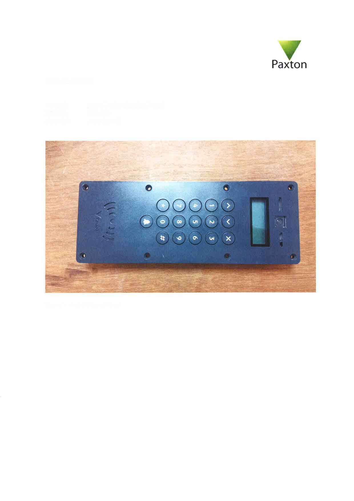
USE337420
Sep 17, 2015Door access system operating on 125kHz and 13.56MHz
Equipment Class
DCD - Part 15 Low Power Transmitter Below 1705 kHz
USE010387
Apr 29, 2015net10 desktop reader
Equipment Class
DCD - Part 15 Low Power Transmitter Below 1705 kHz