UT650289BA8800ULUplink Booster Amplifier
Airorlite Communications, Inc.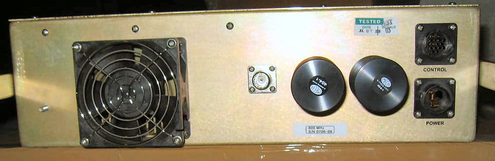
Click to zoom
Application Details
- Equipment Class
- TNB - Licensed Non-Broadcast Station Transmitter
- Date of Grant
- Mar 14, 2007
- Application Purpose
- Original Equipment
- Date of Application
- Feb 27, 2007
- Equipment Note
- Uplink Booster Amplifier
- Frequency Range
- 821.21500000 - 823.91250000
- Country
- United States
Documents & Files
Document Text
Text extracted from the exhibit documents filed with the FCC. Open a document above to read the original.
Users Manual
50289‐BA‐8‐PA ‐1‐ 8 Channel 800MHz Bi‐Directional Booster Amplifier Model 50289‐BA‐8‐PA Operations and Installation Instruction Manual AIRORLITE UNCONDITIONALLY GUARANTEES THE MERCHANDISE PROVIDED AGAINST DEFECTS OF ANY KIND INCLUDING, WITHOUT LIMITATION, DEFECTS IN OPERATION, DESIGN, MATERIALS, AND WORKMANSHIP FOR TWO YEARS FROM THE DATE OF DELIVERY. AIRORLITE IS NOT RESPONSIBLE FOR ANY EQUIPMENT REPAIRED OR ALTERED BY PERSONS NOT AUTHORIZED BY AIRORLITE OR NOT IN ACCORDANCE WITH INSTRUCTIONS FURNISHED BY AIRORLITE. AIRORLITE. IS NOT RESPONSIBLE FOR EQUIPMENT RENDERED DEFECTIVE AS A RESULT OF MISUSE, IMPROPER REPAIR, OR ABNORMAL CONDITIONS OF OPERATION, NOR DOES AIRORLITE ASSUME ANY LIABILITY FOR ANY CONSEQUENTIAL DAMAGE CAUSED BY SUCH EQUIPMENT. SERVICE CONTRACTS OR CUSTOMER ASSISTANCE AGREEMENTS ARE AVAILABLE FOR AIRORLITE PRODUCTS THAT REQUIRE MAINTENANCE AND/OR REPAIR. AIRORLITE ALSO HAS SERVICE AND CONSULTATION CONTRACTS FOR ENTIRE SYSTEM CONFIGURATIONS. 50289‐BA‐8‐PA ‐2‐ SYSTEM SPECIFICATIONS Description SPECIFICATIONS Frequency Range 819‐824 MHz & 864‐869 MHz Outbound Signal ‐ Uplink (# of channels=8) 821.2150 MHz 821.8125 MHz (Uplink channel cards can be programmed to these frequencies only) 822.3750 MHz 822.8750 MHz 823.0125 MHz 823.5500 MHz 823.6000 MHz 823.9125 MHz Inbound Signal ‐ Downlink (# of channels=8) 866.2125 MHz 866.8125 MHz (Downlink channel cards can be programmed to these frequencies only) 867.3750 MHz 867.8750 MHz 868.0125 MHz 868.5500 MHz 868.6000 MHz 868.9125 MHz Channel Bandwidth (Uplink/Downlink) 25 kHz Nominal Channel Spacing 25 KHz RF Frequency Accuracy Tracks input signal exactly Adjacent Channel Selectivity 70 dB @ ± 17.5 kHz Fc RF Output Power (Downlink) ~25 dBm/carrier, minimum RF Output Power (Uplink) ~26 dBm/carrier, minimum Variation of Output Power w/Input Level +0, ‐1.0 dB in either direction Maximum Passband Ripple Across Full Band 2 dB Maximum Passband Ripple Across any 100 kHz segment 0.1 dB Amplifier Input Ports (no damage) 0 dBm Propagation Delay 32 microseconds, maximum Intermodulation/Crossmodulation Distortion at Full Output Power ‐60 dBc Channel to Channel Isolation ‐70 dBm Minimum High Band Signal to produce +25 dBm output to Radiating Antenna Cable ‐90 dBm Minimum Low Band Signal to produce full output ‐90 dBm AGC Control Range (Uplink & Downlink) +80 dB Duty Cycle Continuous RF Spurious Output, less than 800 MHz, but greater than 1000 MHz ‐60 dBc, Maximum RF Spurious Output for frequencies ranging from 800 ‐ 1000 MHz ‐85 dBc, Maximum Operating Temperature Range ‐20°C to +60°C System Noise Figure < 9 dB Input/Output Impedance 50 Ohms, nominal Input/Output VSWR 1.35:1, worst case Input/Output Connectors Type “N” Female Input Power 95‐132 VAC, 45‐64 Hz Amplifiers are unconditionally stable under all operating conditions Alarm Loss of Power Supply, DC Change in current draw of +/‐ 20% for each internal amplifier 50289‐BA‐8‐PA ‐3‐ Connection Chart BASIC CONNECTION DIAGRAM 50289‐BA‐8‐PA ‐4‐ BASIC CONNECTION DIAGRAM KEY ID Item 1 Item 2 W1 Downlink Power Amp Output Downlink Radiator W5 Duplexer Antenna Port "Off the Air" Antenna W6 Duplexer Downlink Downlink 8 Way Splitter W7 Duplexer Uplink Uplink Power Amplifier Output W9 Uplink 8 Way Splitter Uplink Radiator W10 Uplink 8 Way Combiner Uplink Power Amplifier Input W14 Downlink 8 Way Combiner Downlink Power Amplifier Input The Basic Connection Diagram shown above, is the proper way the BDA should be connected and once up and running, require minimal to none manual configuration. Connections between cabinets are made through N‐Bulkhead connectors located on the top of each cabinet. All programming and adjusting is done through the software and this manual primarily deals with this topic. The computer running the software is connected via an RS232 serial cable to each channel card in the manner shown below. 50289‐BA‐8‐PA ‐5‐ MAIN SCREEN Below is the main working screen used to configure the channel card settings. The primary fields addressed are: • Communication Connection • Time Out Timer • Mode Setting • Key On Delay • Key Off Delay • Attenuation • Setting a Frequency 50289‐BA‐8‐PA ‐6‐ COMMUNICATION CONNECTION This software automatically checks the condition of its communication with the intended channel. Each message is acknowledged and displayed in the message box at the bottom of the screen. If the software does not receive a response from the channel, a warning message is displayed, “NO RESPONSE FROM UNIT”. 50289‐BA‐8‐PA ‐7‐ TIME OUT DURATION The time‐out duration is how long a channel can be held open (keyed on) for a retransmission. An inadvertent or intentional “key and hold” action without any voice communication will not disable the channel because of this feature. The time‐out duration can be up set from 1 second to 99 seconds 1 second intervals. The time‐out duration can be disabled by setting it to 00, when disabled, the channel will key continuously with the presence of a received signal. SETTING A TIME‐OUT TIME To set a time‐out time, click on the text box “Time Out Timer” and enter the desired time‐out time up to 99 seconds then click “Send Button” next to the box. To verify the setting, click on the “Read Button” and the display will be updated with the channel setting. 50289‐BA‐8‐PA ‐8‐ MODE SETTING The channel mode may be set to either INHIBIT, CONTINUOUS, CARRIER DETECT or optional TONE DETECT. In the Inhibit mode, the channel is off and will not key on. In the continuous mode, CW, the channel is always keyed and continuously transmitting. In the carrier detect mode, CD, the channel is keyed only when the incoming signal strength is above the factory set threshold level. Normal operation will be in CD mode; continuous mode is normally used for testing. CHANGING THE MODE To change the Mode, click the desired function box on Mode Selection on the main screen. Then click “Send Button” next to the box. To verify the setting, click on the “Read Button” and the display will be upd…
Text truncated - open the document above for the full version.
Attestation Statements
March 7, 2007 Mr. Tim Johnson American TCB 6731 Whittier Avenue, Suite C110 McLean, VA 22101 RE: Emailed comments APPLICATION: UT650289BA8800UL (ATCB4546) Dear Mr. Johnson: Below are the questions regarding this application posed to Washington Laboratories, Ltd. via email, and our responses. Please do not hesitate to contact us, should you have any questions. Sincerely, Steven D. Koster Brian J. Dettling EMC Operations Manager Documentation Specialist WLL Project #: 9520 7560 Lindbergh Drive Gaithersburg, Maryland 20879 (301) 417-0220 Fax (301) 417-9069 website: http://www.wll.com email: [email protected] 1) It appears that frequency translation is possible from looking at the block diagram, however operational description suggests that the TX frequency is same as incoming. However tables in the manual suggest only 8 channels can be output, but the software screens shown a large number of any 25 kHz channels as possible. The information is confusing and solid understanding on the operation and if it incorporates translation can not be determined. This should be clear as to understand how the device operates. Note that if it does translate frequencies, then frequency stability is required. a.) The device does not translate frequencies. The incoming signal is mixed with an LO to down- convert to 90 MHz and after filtering and amplification, the 90MHz is mixed with the same LO so the input and output frequencies remain the same. b.) The output RF will, therefore, not change with temperature or voltage variation. c.) The software is Airorlite’s general software. The frequencies for this device are listed in the table on page 2 of the manual. 2) The test report and other documentation states this is a bi-directional booster. If it were bi-directional we would expect to see the uplink data. Uplink info is in the other application, so apparently both applications make up the bi-directional aspect. If this is the case then the terminology is not correct as each device being certified would only be a directional booster/repeater and not bi-directional booster. The operational description, manual and test report and other documentation must make this fact clear. Currently the operational description will red-flag this application because it discusses a bi-directional amplifier. At a minimum, a note should be added to the PDF file that only the downlink amplifier portion of this system is being Certified. Otherwise first impressions are that what is Certified and what the operational description is are two different items. A similar problem can be assumed about the block diagram. The block diagram is actually system level but was not clearly understood what part of it covers the application until deep into the application itself. It would be best for the block diagram to have a note or markings showing what part of the system the application is covering. The report in each case has been edited to show that there are two applications: One is for a downlink booster and the other is for an uplink booster. The system as a whole is a Bi-directional booster; this application is for the uplink channels. 3) I did not find any information regarding the emissions the device/system is designed to use in the manual or operational description. The test report simply cited "depends on system". Amplifier guidance "attached" clearly states investigation of the different modulations is required for certain tests (i.e. power, conducted spurious, intermodulation, and input/output bandwidths - but see guidance for complete detail). Therefore justification as to the F1E designator should be provided and depending on intended use of the device - additional emissions may need to be investigated for certain tests. As is, this device could only be used for F1E signals. The Form 731 (50289UL Application Form - 731 revised 3.07) has been revised accordingly: The emission designator has been changed to “F8E”. The system is employed to augment analogue, frequency modulated voice communications. The device is capable of 8 channels of operation. Hence, from FCC 2.201: F: Frequency Modulation 8: One or more channels containing analogue information E: Telephony 4) Frequency tolerance should cite "amp" unless frequency translation occurs (as mentioned above). The Form 731 has been revised accordingly. 5) Given the uplink/downlink are separate, to clarify this and how the device is used, the grant notes should contain: “Part of booster system used with FCC ID: xxxyyy.” Acknowledged. 6) Booster rules cites: – Include exhibit or correspondence showing applicant was informed that boosters must meet all criteria stated in Sections 90.219 and 22.383 for related booster/inbuilding operations. NOTE: THIS APPEARS TO BE A CLASS B DEVICE UNDER 90.219, AND IF SO, SHOULD ADEQUATELY JUSTIFY AS SUCH. The applicant is informed. See letter (Airorlite Pt90.219 Letter). 7) While radiated spurious may use a CW signal, conducted spurious requires to test all modulation types [TDMA, CDMA, and FM (covers GSM andF1D)] at low, mid. and high frequency. Given 3) above, it is uncertain if this is covered appropriately. This device is designed to be used with FM input/output signals. Other modulation types are not required to be characterized. 8) There does not appear to be information to support that input drive level is at maximum input rating and maximum gain settings for all tests. Given this is basically and amplifier, this should be documented/justified....Additionally an explanation of what keeps the device from going into saturation should be provided...Generally amplifiers, booster, and repeaters must justify the levels used for test and document them as appropriate. See attached guidance as well... The drive level was supplied by the customer. The optimal drive level was derived from empirical measurements provided by the customer on actual installations. A -50dBm level was found to represent the highest incoming stimulus signal. 9) Power on grant should …
Text truncated - open the document above for the full version.
Attestation Statements
March 7, 2007 Mr. Tim Johnson American TCB 6731 Whittier Avenue, Suite C110 McLean, VA 22101 RE: Emailed comments APPLICATION: UT650289BA8800UL (ATCB4546) Dear Mr. Johnson: Below are the questions regarding this application posed to Washington Laboratories, Ltd. via email, and our responses. Please do not hesitate to contact us, should you have any questions. Sincerely, Steven D. Koster Brian J. Dettling EMC Operations Manager Documentation Specialist WLL Project #: 9520 7560 Lindbergh Drive Gaithersburg, Maryland 20879 (301) 417-0220 Fax (301) 417-9069 website: http://www.wll.com email: [email protected] 1) It appears that frequency translation is possible from looking at the block diagram, however operational description suggests that the TX frequency is same as incoming. However tables in the manual suggest only 8 channels can be output, but the software screens shown a large number of any 25 kHz channels as possible. The information is confusing and solid understanding on the operation and if it incorporates translation can not be determined. This should be clear as to understand how the device operates. Note that if it does translate frequencies, then frequency stability is required. a.) The device does not translate frequencies. The incoming signal is mixed with an LO to down- convert to 90 MHz and after filtering and amplification, the 90MHz is mixed with the same LO so the input and output frequencies remain the same. b.) The output RF will, therefore, not change with temperature or voltage variation. c.) The software is Airorlite’s general software. The frequencies for this device are listed in the table on page 2 of the manual. 2) The test report and other documentation states this is a bi-directional booster. If it were bi-directional we would expect to see the uplink data. Uplink info is in the other application, so apparently both applications make up the bi-directional aspect. If this is the case then the terminology is not correct as each device being certified would only be a directional booster/repeater and not bi-directional booster. The operational description, manual and test report and other documentation must make this fact clear. Currently the operational description will red-flag this application because it discusses a bi-directional amplifier. At a minimum, a note should be added to the PDF file that only the downlink amplifier portion of this system is being Certified. Otherwise first impressions are that what is Certified and what the operational description is are two different items. A similar problem can be assumed about the block diagram. The block diagram is actually system level but was not clearly understood what part of it covers the application until deep into the application itself. It would be best for the block diagram to have a note or markings showing what part of the system the application is covering. The report in each case has been edited to show that there are two applications: One is for a downlink booster and the other is for an uplink booster. The system as a whole is a Bi-directional booster; this application is for the uplink channels. 3) I did not find any information regarding the emissions the device/system is designed to use in the manual or operational description. The test report simply cited "depends on system". Amplifier guidance "attached" clearly states investigation of the different modulations is required for certain tests (i.e. power, conducted spurious, intermodulation, and input/output bandwidths - but see guidance for complete detail). Therefore justification as to the F1E designator should be provided and depending on intended use of the device - additional emissions may need to be investigated for certain tests. As is, this device could only be used for F1E signals. The Form 731 (50289UL Application Form - 731 revised 3.07) has been revised accordingly: The emission designator has been changed to “F8E”. The system is employed to augment analogue, frequency modulated voice communications. The device is capable of 8 channels of operation. Hence, from FCC 2.201: F: Frequency Modulation 8: One or more channels containing analogue information E: Telephony 4) Frequency tolerance should cite "amp" unless frequency translation occurs (as mentioned above). The Form 731 has been revised accordingly. 5) Given the uplink/downlink are separate, to clarify this and how the device is used, the grant notes should contain: “Part of booster system used with FCC ID: xxxyyy.” Acknowledged. 6) Booster rules cites: – Include exhibit or correspondence showing applicant was informed that boosters must meet all criteria stated in Sections 90.219 and 22.383 for related booster/inbuilding operations. NOTE: THIS APPEARS TO BE A CLASS B DEVICE UNDER 90.219, AND IF SO, SHOULD ADEQUATELY JUSTIFY AS SUCH. The applicant is informed. See letter (Airorlite Pt90.219 Letter). 7) While radiated spurious may use a CW signal, conducted spurious requires to test all modulation types [TDMA, CDMA, and FM (covers GSM andF1D)] at low, mid. and high frequency. Given 3) above, it is uncertain if this is covered appropriately. This device is designed to be used with FM input/output signals. Other modulation types are not required to be characterized. 8) There does not appear to be information to support that input drive level is at maximum input rating and maximum gain settings for all tests. Given this is basically and amplifier, this should be documented/justified....Additionally an explanation of what keeps the device from going into saturation should be provided...Generally amplifiers, booster, and repeaters must justify the levels used for test and document them as appropriate. See attached guidance as well... The drive level was supplied by the customer. The optimal drive level was derived from empirical measurements provided by the customer on actual installations. A -50dBm level was found to represent the highest incoming stimulus signal. 9) Power on grant should …
Text truncated - open the document above for the full version.
Cover Letter(s)
A.DIVISON.OF.HENRY.BROTHERS.ELECTRONICS 17-01 Pollitt Drive Fair Lawn, New Jersey 07410 Phone: 201.398.0960 Fax: 201.398.0962 LETTER OF AGENCY December 18, 2006 American Telecommunications Certification Body, Inc. 6731 Whittier Avenue Suite C110 McLean, VA 22101 To Whom It May Concern: Please be advised that Airorlite Communications, Inc. authorizes Washington Laboratories, Ltd. to act on our behalf, until otherwise notified, for applications submitted to American Telecommunications Certification Body, Inc. (ATCB). We certify that we are not subject to denial of federal benefits that includes FCC benefits, pursuant to Section 5301 of the Anti-Drug Abuse ACT of 1988, U.S.C. 862. Further, no party, as defined in 47 CFR 1.2002(b), to the application is subject to denial of federal benefits, that includes FCC benefits. Thank you for your attention to this matter. Regards, Lee Masoian President
Cover Letter(s)
A.DIVISON.OF.HENRY.BROTHERS.ELECTRONICS 17-01 Pollitt Drive Fair Lawn, New Jersey 07410 Phone: 201.398.0960 Fax: 201.398.0962 REQUEST FOR CONFIDENTIALITY December 18, 2006 American Telecommunications Certification Body, Inc. 6731 Whittier Avenue Suite C110 McLean, VA 22101 RE: Certification Application FCC ID: UT650289BA8800UL Please be advised that under the provision of 47 CFR 0.459 the following exhibits are to be held confidential on behalf of Airorlite Communications, Inc. • Operational Description • Tune-Up Procedure • User’s Manual • Block Diagram • Schematics • Parts List • Internal Photos The application contains technical information that Airorlite Communications, Inc. deems to be trade secrets and proprietary. If made public, the information might be used to the disadvantage of the applicant in the market place. Thank you for your attention to this matter. Regards, Lee Masoian President
External Photos
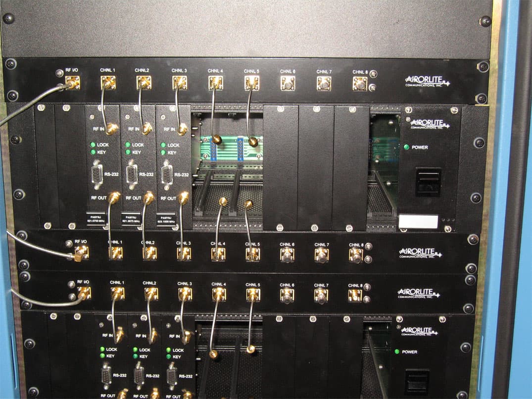
External Photos – Channel Card ©2006 Washington Laboratories, Ltd External Photos – Channel Card ©2006 Washington Laboratories, Ltd External Photos – Channel Card ©2006 Washington Laboratories, Ltd External Photos – Channel Card ©2006 Washington Laboratories, Ltd
External Photos
External Photos – Power Amplifier ©2006 Washington Laboratories, Ltd
External Photos
External Photos – Splitter/Combiner ©2006 Washington Laboratories, Ltd External Photos – Splitter/Combiner ©2006 Washington Laboratories, Ltd External Photos – Splitter/Combiner ©2006 Washington Laboratories, Ltd External Photos – Splitter/Combiner ©2006 Washington Laboratories, Ltd
ID Label/Location Info
FCC ID: UT650289BA8800UL MODEL: 50289 MANUFACTURED BY AIRORLITE COMMUNICATIONS, INC. S/N Label Location (Uplink and Downlink)
Internal Photos
Internal Photos – Channel Card ©2006 Washington Laboratories, Ltd Internal Photos – Channel Card ©2006 Washington Laboratories, Ltd Internal Photos – Channel Card ©2006 Washington Laboratories, Ltd Internal Photos – Channel Card ©2006 Washington Laboratories, Ltd Internal Photos – Channel Card ©2006 Washington Laboratories, Ltd Internal Photos – Channel Card ©2006 Washington Laboratories, Ltd Internal Photos – Channel Card ©2006 Washington Laboratories, Ltd
Internal Photos
Internal Photos – Power Amplifier ©2006 Washington Laboratories, Ltd Internal Photos – Power Amplifier ©2006 Washington Laboratories, Ltd Internal Photos – Power Amplifier ©2006 Washington Laboratories, Ltd Internal Photos – Power Amplifier ©2006 Washington Laboratories, Ltd Internal Photos – Power Amplifier ©2006 Washington Laboratories, Ltd Internal Photos – Power Amplifier ©2006 Washington Laboratories, Ltd Internal Photos – Power Amplifier ©2006 Washington Laboratories, Ltd Internal Photos – Power Amplifier ©2006 Washington Laboratories, Ltd
Internal Photos
Internal Photos – Splitter/Combiner ©2006 Washington Laboratories, Ltd Internal Photos – Splitter/Combiner ©2006 Washington Laboratories, Ltd Internal Photos – Splitter/Combiner ©2006 Washington Laboratories, Ltd
RF Exposure Info
Document 9250-MPE FCC ID: UT650289BA8800UL FCC ID: UT650289BA8800DL RF Exposure Test Report Washington Laboratories, Ltd February 2007 Maximum Permissible Exposure Evaluation for AIRORLITE COMMUNICATIONS, INC. Model 50289 Bi-Directional Booster FCC ID: UT650289BA8800UL FCC ID: UT650289BA8800DL February 20, 2007 WLL PROJECT #: 9520 This report may not be reproduced, except in full, without the prior written consent of Washington Laboratories, Ltd. RF Exposure Evaluation Document 9250-MPE FCC ID: UT650289BA8800UL FCC ID: UT650289BA8800DL RF Exposure Test Report Washington Laboratories, Ltd February 2007 1 Maximum Permissible Exposure Test Report for FCC ID: UT650289BA8800UL FCC ID: UT650289BA8800DL 1.0 Introduction This report has been prepared to show compliance with the RF exposure requirements as defined in FCC §1.1307. 1.1 Requirements Three different categories of transmitters are defined by the FCC in OET Bulletin 65. These categories are fixed installation, mobile, and portable and are defined as follows: Fixed Installations: fixed location means that the device, including its antenna, is physically secured at a permanent location and is not able to be easily moved to another location. Additionally, distance to humans from the antenna is maintained to at least 2 meters. Mobile Devices: a mobile device is defined as a transmitting device designed to be used in other than fixed locations and to be generally used in such a way that a separation distance of at least 20 centimeters is normally maintained between the transmitter's radiating structures and the body of the user or nearby persons. Transmitters designed to be used by consumers or workers that can be easily re-located, such as a wireless modem operating in a laptop computer, are considered mobile devices if they meet the 20 centimeter separation requirement. The FCC rules for evaluating mobile devices for RF compliance are found in 47 CFR §2.1091. Portable Devices: a portable device is defined as a transmitting device designed to be used so that the radiating structure(s) of the device is/are within 20 centimeters of the body of the user. Portable device requirements are found in Section 2.1093 of the FCC's Rules (47 CFR§2.1093). For this report the Airolite Communications Inc Booster with 7.1 dBi antenna is under consideration. The FCC also categorizes the use of the device as based upon the user’s awareness and ability to exercise control over his or her exposure. The two categories defined are Occupational/ Document 9250-MPE FCC ID: UT650289BA8800UL FCC ID: UT650289BA8800DL RF Exposure Test Report Washington Laboratories, Ltd February 2007 2 Controlled Exposure and General Population/Uncontrolled Exposure. These two categories are defined as follows: Occupational/Controlled Exposure: In general, occupational/controlled exposure limits are applicable to situations in which persons are exposed as a consequence of their employment, who have been made fully aware of the potential for exposure and can exercise control over their exposure. This exposure category is also applicable when the exposure is of a transient nature due to incidental passage through a location where the exposure levels may be higher than the general population/uncontrolled limits, but the exposed person is fully aware of the potential for exposure and can exercise control over his or her exposure by leaving the area or by some other appropriate means. Awareness of the potential for RF exposure in a workplace or similar environment can be provided through specific training as part of a RF safety program. If appropriate, warning signs and labels can also be used to establish such awareness by providing prominent information on the risk of potential exposure and instructions on methods to minimize such exposure risks. General Population/Uncontrolled Exposure: The general population / uncontrolled exposure limits are applicable to situations in which the general public may be exposed or in which persons who are exposed as a consequence of their employment may not be made fully aware of the potential for exposure or cannot exercise control over their exposure. Members of the general public would come under this category when exposure is not employment-related; for example, in the case of a wireless transmitter that exposes persons in its vicinity. Warning labels placed on low-power consumer devices such as cellular telephones are not considered sufficient to allow the device to be considered under the occupational/controlled category, and the general population/uncontrolled exposure limits apply to these devices. Since there are no warnings or training associated with this unit and it can be used by anyone, the AIRORLITE Communications Inc.. Model 50289 Bi-Directional Booster is evaluated to the General Population/Uncontrolled Exposure limits. 1.2 Radio Frequency Radiation Exposure Evaluation The highest RF output power of the unit was measured is recorded. According to §1.1310 of the FCC rules, the power density limit for General Population/Uncontrolled Exposure is 1mW/cm 2 . As this is a modular approval the MPE shall be calculated at 20cm to show compliance with the power density limit. The following formula was used to calculate the Power Density: 2 4R PG S π = Where: S = Power Density Document 9250-MPE FCC ID: UT650289BA8800UL FCC ID: UT650289BA8800DL RF Exposure Test Report Washington Laboratories, Ltd February 2007 3 P = Output Power at the Antenna Terminals G = Gain of Transmit Antenna (linear gain-isotropic) R = Distance from Transmitting Antenna The limit is calculated at the lowest frequency for both the Uplink and the Downlink bands as this provides the lowest limit and is therefore the most conservative. The device is designed for fixed installation. The results of the MPE calculation are shown below. Single Transmitter Frequency 819MHz Limit0.546 mW/cm^2 Distance (cm), R =20cm Power (dBm), P =22.6dBm TX Ant Gain (dB), G =7.1dB MPE 0.19 m…
Text truncated - open the document above for the full version.
RF Exposure Info
Document 9250 UL-MPE FCC ID: UT650289BA8800UL RF Exposure Test Report Washington Laboratories, Ltd March 2007 Revision 1 Maximum Permissible Exposure Evaluation for AIRORLITE COMMUNICATIONS, INC. Model 50289 Bi-Directional Booster FCC ID: UT650289BA8800UL Revision 1: March 13, 2007 WLL PROJECT #: 9520-UL MPE This report may not be reproduced, except in full, without the prior written consent of Washington Laboratories, Ltd. RF Exposure Evaluation Document 9250-MPE FCC ID: UT650289BA8800UL RF Exposure Test Report Washington Laboratories, Ltd March 2007 1 Maximum Permissible Exposure Test Report for FCC ID: UT650289BA8800UL 1.0 Introduction This report has been prepared on behalf of AIRORLITE COMMUNICATIONS, INC. MODEL 50289 BI-DIRECTIONAL BOOSTER. This report is for the uplink portion of the system. The uplink receives over the in building/tunnel radiator and boosts the power and then re-transmits over the roof antenna. This report is to show compliance with the RF exposure requirements as defined in FCC §1.1307. 1.1 Requirements Three different categories of transmitters are defined by the FCC in OET Bulletin 65. These categories are fixed installation, mobile, and portable and are defined as follows: Fixed Installations: fixed location means that the device, including its antenna, is physically secured at a permanent location and is not able to be easily moved to another location. Additionally, distance to humans from the antenna is maintained to at least 2 meters. Mobile Devices: a mobile device is defined as a transmitting device designed to be used in other than fixed locations and to be generally used in such a way that a separation distance of at least 20 centimeters is normally maintained between the transmitter's radiating structures and the body of the user or nearby persons. Transmitters designed to be used by consumers or workers that can be easily re-located, such as a wireless modem operating in a laptop computer, are considered mobile devices if they meet the 20 centimeter separation requirement. The FCC rules for evaluating mobile devices for RF compliance are found in 47 CFR §2.1091. Portable Devices: a portable device is defined as a transmitting device designed t…
Text truncated - open the document above for the full version.
Contact Information
Applicant
John Nashmy(Program Manager)
Technical Contact
Washington LabsGreg Snyder
[email protected]301 417 0220
7560 Lindbergh Drive · Gathersburh · United States
Non-Technical Contact
Washington LabsBrian Dietling
Technical Specifications
| # | Rule Parts | Frequency Range | Power Output | Emission | Tolerance |
|---|---|---|---|---|---|
| 1 | 90,90 | 821.215 MHz - 823.9125 MHz | 375.00 mW | F1E | Amp |
Other Applications from Airorlite Communications, Inc.
UT650289BAX8800DL
Sep 04, 2007Downlink Booster Amplifier
Equipment Class
TNB - Licensed Non-Broadcast Station Transmitter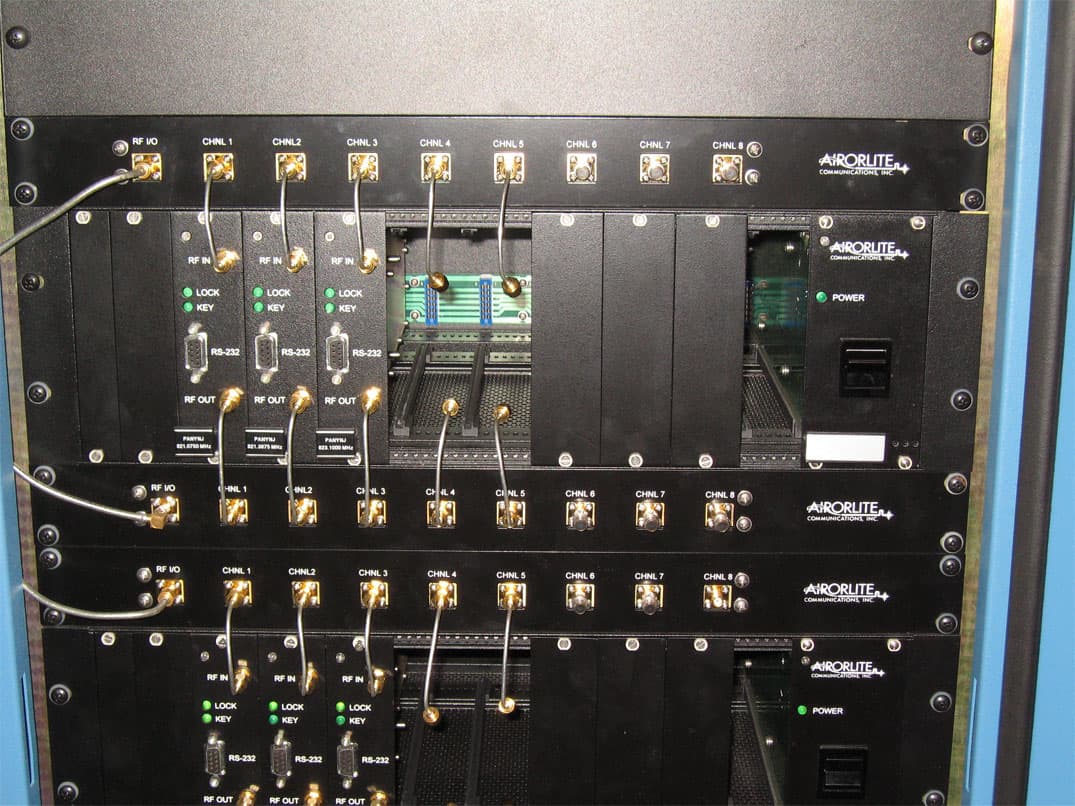
UT650289BAX8800UL
Sep 03, 2007Uplink Booster Amplifier
Equipment Class
TNB - Licensed Non-Broadcast Station Transmitter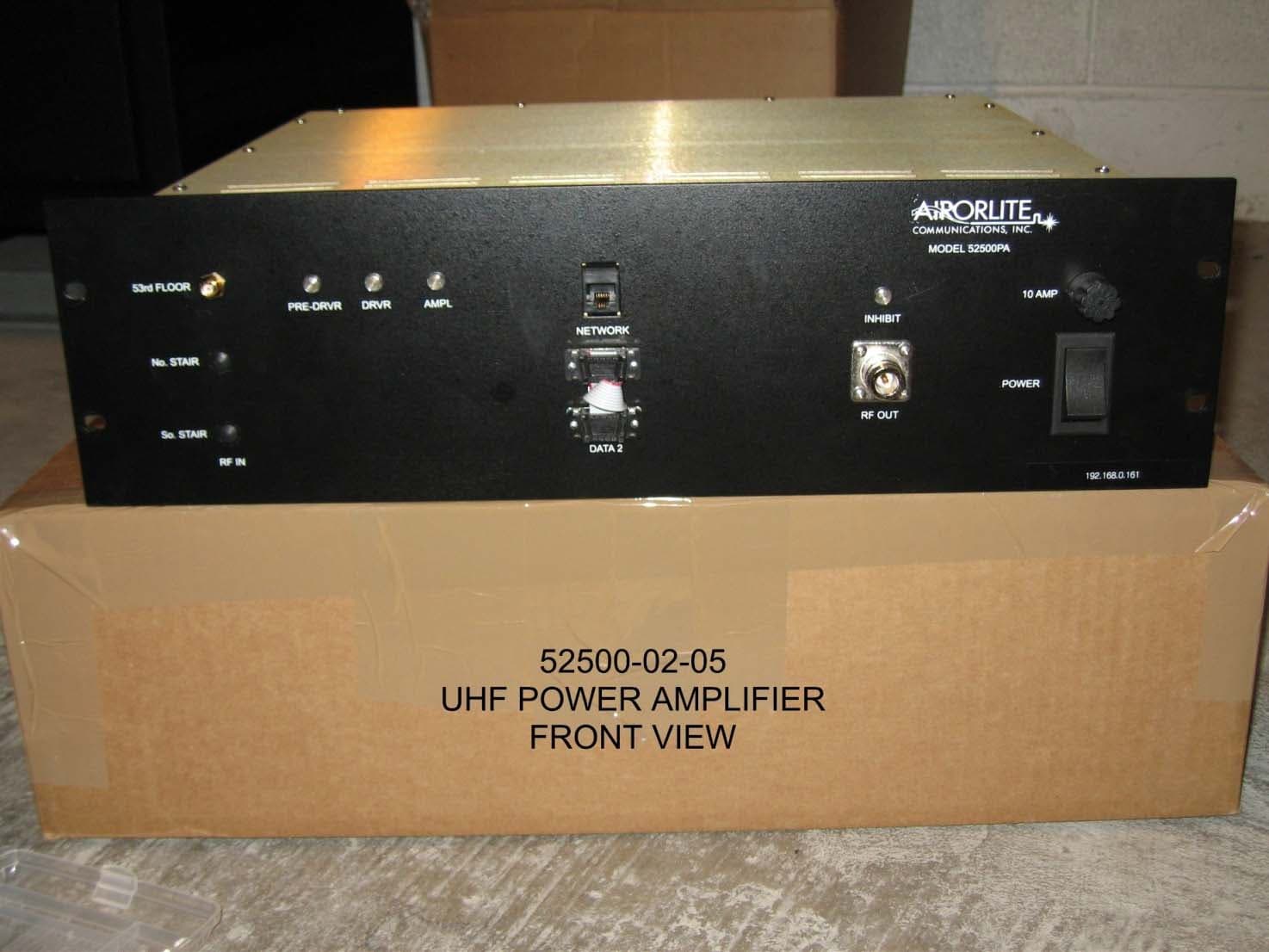
UT650289BA8470DL
Jul 23, 2007Downlink Booster Amplifier
Equipment Class
TNB - Licensed Non-Broadcast Station Transmitter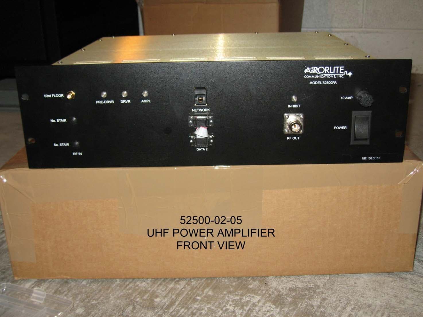
UT650289BA8480UL
Jul 20, 2007Uplink Booster Amplifier
Equipment Class
TNB - Licensed Non-Broadcast Station Transmitter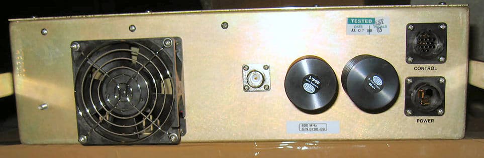
UT650289BA8800DL
Mar 14, 2007Downlink Booster Amplifier
Equipment Class
TNB - Licensed Non-Broadcast Station Transmitter