UTOMP1045FM Transmitter with remote
ESI Cases and Accessories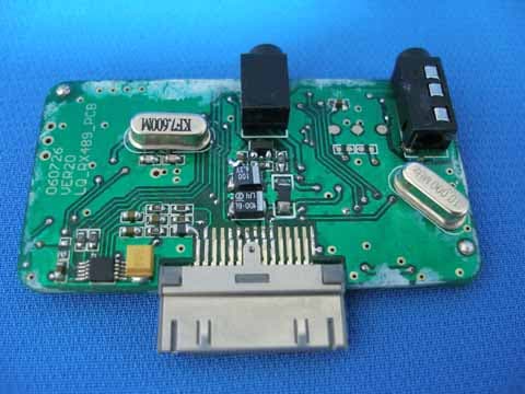
Click to zoom
Application Details
- Equipment Class
- DXX - Part 15 Low Power Communication Device Transmitter
- Date of Grant
- Jun 10, 2007
- Application Purpose
- Original Equipment
- Date of Application
- Jun 10, 2007
- Equipment Note
- FM Transmitter with remote
- Frequency Range
- 88.00000000 - 107.90000000
- Company
- ESI Cases and Accessories
- Country
- United States
Documents & Files
Document Text
Text extracted from the exhibit documents filed with the FCC. Open a document above to read the original.
Users Manual
Remote controller assembly Remote controller includes front-boardPCBAbackboard (with clip) and holder-board. Connecting the backboard to PCBA board according to sharp, then cover the front-board after fastening them together with screw. Holder-board is designed in order t to user hold controller more convenience. It will connect together so long as you clamp holder-board with the clip of backboard. Host assembly The host consists of front-boardPCBA and backboard. There’re three I/O port on PCBA board: earphone portcharge port and data linker port. Assembling them together according to port type of PCBA notching conditions of front-board and backboard, then fastening them with gluewater.
Cover Letter(s)
1 How does this device operate? The FM transmitter is a FM stereo transmitting configuration,which radiates FM wave on the air by modulating the any required signal to the carrier signal. The transmission frequency is set 88.1~107.9MHz. Operating Instructions: (1). Ipod will open and play automatically after being plugged into the equipment. Synchronously, FM indicator light of equipment will light and FM working frequency will be shown on the screen of ipod. During the period, “FUN” key on the remote controller could close FM; or FM frequency could be adjusted by “UP/DOWN” key.The show mode will be exited after FM isn’t operated for ten seconds.(notice: It’s forbidden which ipod keystroke operated in show mode.) (2). After exitting the show mode, We could control the function of ipod by operating ipod or remote controller: play/pause, volume+, volume-, skip>>, skip<<. Operating “FUN’ key on the remote controller will control FM switch; and operating “UP/DOWN” key on the remote controller will control FM frequency. (notice: It’s useless when FM is closed , it will enter 1. function when FM is adjusted or open.) (3). It will close FM function automatically if earphone is inserted. (4). Indicator light of equipment shows FM working conditions. 2) Provide information on the device and its antenna. The device consists of the host and remote controller. The host consists of front-boardPCBA and backboard. Remote controller includes front-boardPCBAbackboard (with clip) and holder-board. About antenna information, please see attachment. 3)How is it installed? The FM transmitter is powered by ipod’s power. It can be connected to ipod earphone. 4)What test procedure was used? ANSI C63.4, the test was performed in 10m OATS. 5)If tested in a car, how was it configured/tested? It's not tested in a car. Not used in car. 6Was the tuning range properly verified? The test lab should indicate in the report that the tuning controls were manually adjusted to verify maximum tuning range. Channel low (88.1MHz), Ch mid (98MHz), Ch high (107.9MHz), with highest data rate (worst case) are chosen for full testing. The working frequency can be displayed and adjusted on EUT. We have indicated the testing in the test report ,see clause 3.5. 7) Was the bandwidth properly tested with maximum audio input? The test was performed with the maximum audio input. And set EUT as normal operation (playing MP3) We have indicated the operating condition in the test report,see clause 3.5.
External Photos
EUT EXTERIOR PHOTO Applicant: ESI CASES AND ACCESSORIES FCC ID: UTOMP1045
ID Label/Location Info
Applicant: ESI CASES AND ACCESSORIES FCC ID: UTOMP1045 This device complies with part 15 the FCC rules. Operation is subject to the following two condition: (1). This device may not case harmful interference, (2).This device must accept any interference received, including interference that may cause undesired operation Proposed Label Location On EUT EUT Bottom View/Proposed FCC ID LABEL location FCC ID: UTOMP1045
Internal Photos
EUT INSIDE PHOTO Applicant: ESI CASES AND ACCESSORIES FCC ID: UTOMP1045
Operational Description
Applicant: ESI CASES AND ACCESSORIES FCC ID: UTOMP1045 Antenna Note: This is the normal 26AWG cable. The cable’s length is 2.5cm.
Operational Description
Operating Description Wireless Audio Link IC BH 1418 FV The BH1418FV is a FM stereo transmitter IC used for audio systems. The transmitter consists pre-emphasis circuit,limiter circuit, low-pass filter circuit. And, built-in the pilot-ton system FM stereo modulator circuit for generating stereo composite signals. And, PLL system FM transmitter circuit for broadcasting a FM signal on the air which data input (CE,CK,DA)by serial input. And, built-in the sound muting circuit.
Schematics
1 2 34 ABCD 4 3 2 1 D CBA Title Number Revision Size A4 Date: 4-Sep-2006 Sheet of File: D:\design\ \ \RF \ \Tai ch iu n_ip od &FM&RF&di sp lay.dd b Drawn By: C23332PC24151P R17203 C36 C34102P R19 101 C41 473P C40 100uF R20 R24 332 C42102P R23 332 Q3 R21 103 L10 C39 C33 103P C20 151P C21 332P C22 1uF R18 103 R12222 C43 471 R25 103 C2510uF C27 27P C28 27P C26105 D2 KV-1471E R10 333 R11472 R13 333 R12 472 Y17.6MHz C37 C35 105 R16203 C46 102P Q2 2SC3356 R15 333 L9 100uH R14100R L12 0R C31 471P L4FM_ANT 1 2 3 4 5 6 7 8 9 10 11 1213 14 15 16 17 18 19 20 21 22 23 24 U1 BH1418FV FM_1418 L7 1uH NC C4710P***NC L1382nHNC AUD_LAUD_RAUD_REFFM_CEFM_CLKFM_DATA V_CTRL L81uH C44103P C32100uF C4510uF C29100uF C30103P C38107P C19CAP
Schematics
1 2 3 4 56 ABCD 6 5 4 3 2 1 D CBA Title Number Revision Size B Date: 4-Sep-2006 Sheet of File: D:\des ig n\ \ \RF \ \Tai chi un_i pod &FM&RF&di sp lay.dd b Drawn By: TXDRXD 123456789 101112131415161718192021222324252627282930 JK2ipod_connector R2 101 R3 101 RXD1TXD1ID R4564 AUD_REF AUD_LAUD_R + C5107P + C6107P L2100uH VDD VCC C13104P SHUTUPDNP_CLK VDD LIUQING_RF CH+CH- CH- CH+ 123 JK1DC_JACK(12V) AUD_L_OUTAUD_R_OUT V_CTRL BH1418_M OUDLE FM_CEFM_CLKFM_DATA (RESET) PC6 29 PD0 (RXD) 30 PD1 (TXD) 31 PD2(INT0) 32 PD3 (INT1) 1 PD4 (XCK/T0) 2 VCC 6 GND 3 PB6 (XTAL1/TOSC1) 7 PB7 (XTAL2/TOSC2) 8 PD5 (T1) 9 PD6 (AIN0) 10 PD7 (AIN1) 11 PB0 (ICP) 12 PB1 (OC1A) 13 PB2 (SS/OC1B) 14 PB3 (MOSI/OC2) 15 PB4 (MISO) 16 PB5 (SCK) 17 AVCC 18 AREF 20 GND 21 (ADC0) PC0 23 (ADC1) PC1 24 (ADC2) PC2 25 (ADC3) PC3 26 (ADC4/SDA) PC4 27 (ADC5/SCL) PC5 28 ADC6 19 ADC7 22 VCC 4 GND 5 U2 ATMEGA48VAU10 TXDRXD VDD FM_CEFM_CLKFM_DATA C14104P FM_POWOSC1OSC2 1 2 Y17.3728 OSC1 OSC2 SHUTP_CLKUPDN R5102 Q1 APM2313 FM_POW V_CTRL C7104P VCC R9102 /RADIO_LED /RADIO_LED 12345678 910111213141516 U1RX489 12 X110M R1102 VCC L11uH C2105P C3101P C410P RF_VCC RF_VCC C1104P C93P 1RF_RX_ANT L315nHNC C83P D1 RADIO_LED JR5 102JR6 102 VOUT1 1 VIN1 2 BYPASS 3 CLOCK 4 GND 5 UP/DN 6 SHUT 7 VIN2 8 VOUT2 9 VDD 10 U5LM4811MM + C1647uF + C1547uF + JC41uF + JC11uF + JC31uF + JC21uF JR1103JR2103 JR4102 JR3102 AB AUD_R_OUT AUD_L_OUT JL21uH V20 T1 JK3PHONEJACK-4J MODE MODE VCC R26104 C18104P RF_A0RF_A1RF_A2RF_A3RF_A4 RF_A0RF_A1RF_A2RF_A3RF_A4
Test Report
FCC 47 CFR PART 15 SUBPART C TEST REPORT For ESI CASES AND ACCESSORIES FM Transmitter with remote Model: MP1045 Trade Name: N/A Prepared for ESI CASES AND ACCESSORIES 240 MADISON AVE 11 FLOOR NEW YORK NY 10016 Prepared by SINTEK LABORATORY CO., LTD. No. 7, Xinshidai Industrial, Guantian Village, Shiyan Town, Bao`an District, Shenzhen,Guangdong, P.R.C. TEL: 86-755-27604866 FAX: 86-755-27608359 Note: This report shall not be reproduced except in full, without the written approval of Sintek Laboratory Co.,Ltd. This document may be altered or revised by Sintek Laboratory Co.,Ltd. personnel only, and shall be noted in the revision section of the document. Page 1 of 24 TABLE OF CONTENTS 1.TEST RESULT CERTIFICATION............................................................................................. 3 2.EUT DESCRIPTION.................................................................................................................... 4 3.TEST METHODOLOGY............................................................................................................. 5 3.1...................................................................................................................5 EUT CONFIGURATION 3.2...............................................................................................................................5 EUT EXERCISE 3.3........................................................................................................5 GENERAL TEST PROCEDURES 3.4FCC PART 15.205 RESTRICTED BANDS OF OPERATIONS....................................................6 3.5......................................................................................................6 DESCRIPTION OF TEST MODES 4.INSTRUMENT CALIBRATION................................................................................................. 7 5.FACILITIES AND ACCREDITATIONS................................................................................... 8 5.1....................................................................................................................................8 FACILITIES 5.2...................................................................................................................................8 EQUIPMENT 5.3.............................................................................8 LABORATORY ACCREDITATIONS AND LISTING 6.SETUP OF EQUIPMENT UNDER TEST.................................................................................. 9 6.1....................................................................................................9 SETUP CONFIGURATION OF EUT 6.2SUPPORT EQUIPMENT............................................................................................................9 7.FCC PART 15.239 REQUIREMENTS...................................................................................... 10 7.1BANDWIDTH OF EMISSION......................................................................................................10 7.2 RADIATED EMISSIONS...................................................................................................................14 7.3 POWERLINE CONDUCTED EMISSIONS.............................................................................................20 Page 2 1. TEST RESULT CERTIFICATION Applicant: ESI CASES AND ACCESSORIES 240 MADISON AVE 11 FLOOR NEW YORK NY 10016 Equipment Under Test: FM Transmitter with remote Tra de Na me : N/A Model: MP1045 Date of Test: Sep 18 ~ 22, 2006 Report No. : ST0611021 FCC ID : UTOMP1045 APPLICABLE STANDARDS STANDARD TEST RESULT FCC Part 15 Subpart C No non-compliance noted We hereby certify that: The above equipment was tested by SINTEK laboratory co., ltd. The test data, data evaluation, test procedures, and equipment configurations shown in this report were made in accordance with the procedures given in ANSI C63.4: 2001 and the energy emitted by the sample EUT tested as described in this report is in compliance with the requirements of FCC Rules Part 15.239. The test results of this report relate only to the tested sample identified in this report. Approved by: Reviewed by: Page 3 2. EUT DESCRIPTION FM Transmitter with remote Product Tr a de Name N/A Model Number Mp1045 N/A Model Discrepancy DC 3V by IPOD Power Supply 88.1~107.9 MHz Frequency Range Adjustable/but it only transmit one frequency one time Number of Channels /tuning low 88.1MHz/tuning high 107.9MHz The EUT’S antenna is immovable in the interior of the EUT. Antenna Specification Note: This submittal(s) (test report) is intended for FCC ID: UTOMP1045 filing to comply with Section 15.239 of the FCC Part 15, Subpart C Rules. Page 4 3. TEST METHODOLOGY The tests documented in this report were performed in accordance with ANSI C63.4 and FCC CFR 47 2.1046, 2.1047, 2.1049, 2.1051, 2.1053, 2.1055, 2.1057, and 15.239. 3.1 EUT CONFIGURATION The EUT configuration for testing is installed on RF field strength measurement to meet the Commissions requirement and operating in a manner that intends to maximize its emission characteristics in a continuous normal application. 3.2 EUT EXERCISE The EUT was operated in the engineering mode to fix the TX frequency that was for the purpose of the measurements. According to its specifications, the EUT must comply with the requirements of the Section 15.239 under the FCC Rules Part 15 Subpart C. 3.3 GENERAL TEST PROCEDURES Conducted Emissions The EUT is placed on the turntable, which is 0.8 m above ground plane. According to the requirements in Section 13.1.4.1 of ANSI C63.4: 2001, Conducted emissions from the EUT measured in the frequency range between 0.15 MHz and 30MHz using CISPR Quasi-peak and average detector modes. Radiated Emissions The EUT is placed on a turn table, which is 0.8 m above ground plane. The turntable shall rotate 360 degrees to determine the position of maximum emission level. EUT is set 3m away from the receiving antenna, which varied from 1m to 4m to find out the highest…
Text truncated - open the document above for the full version.
Test Setup Photos
TEST SETUP PHOTO Applicant: ESI CASES AND ACCESSORIES FCC ID: UTOMP1045 RADIATED EMISSION TEST
Contact Information
Applicant
Elliot Azoulay(Managing Director)
Test Firm
SinTek Laboratory Co., Ltd.Eric Lin
Technical Specifications
| # | Rule Parts | Frequency Range | Power Output |
|---|---|---|---|
| 1 | 15C | 88 MHz - 107.9 MHz | - |
Other Applications from ESI Cases and Accessories

UTO-UN
Jul 20, 2015FM transmitter
Equipment Class
DXX - Part 15 Low Power Communication Device Transmitter
UTO-BX840
Jul 05, 2015Remote shutter
Equipment Class
DXX - Part 15 Low Power Communication Device Transmitter
UTO-DU7101-1
Dec 16, 2012GOOSENECK FM TRANSMITTER
Equipment Class
DXX - Part 15 Low Power Communication Device Transmitter
UTO-DU7106-1
Dec 16, 2012DU FM TRANSMITTER
Equipment Class
DXX - Part 15 Low Power Communication Device Transmitter
UTO-DU7128
Apr 29, 2012Duracell Gooseneck Transmitter
Equipment Class
DXX - Part 15 Low Power Communication Device Transmitter